Fire By Design All Weather Electronic Ignition User manual
1
WARNING
Improper installation, adjustment, alteration, service or maintenance can cause
injury or property damage. Read the installation, operating and maintenance
instructions thoroughly before installing or servicing this equipment.
WARNING
Do not store or use gasoline or other flammable vapors and liquids in vicinity of
this or any other appliance.
An LP-cylinder not connected for use shall not be stored in the vicinity of this or
any other appliance.
DANGER
If you smell gas:
1. Shut off gas to the appliance.
2. Extinguish any open flame.
3. If odor continues, keep away from appliance and immediately call your
gas supplier or fire department.
WARNING
For Use with NATURAL or LP GAS Only
NO SOLID FUELS TO BE USED WITH THIS SYSTEM
INSTALLER: Leave this manual with the appliance.
CONSUMER: Retain this manual for future reference.
Installation must conform with local codes or, in the absence of local codes, with the
National Fuel Gas Code, ANSI Z223.1 / NFPA 54, or International Fuel Gas Code.
The appliance, when installed, must be electrically grounded in accordance with local codes or, in
the absence of local codes, with the National Electric Code, ANSI/NFPA 70,if applicable.
www.FirebyDesign.com
CARBON MONOXIDE HAZARD
This appliance can produce carbon monoxide which
has no odor.
Using it in an enclosed space can kill you.
Never use this appliance in an enclosed space such
as a camper, tent car or home.
WARNING
FOR OUTDOOR
USE ONLY
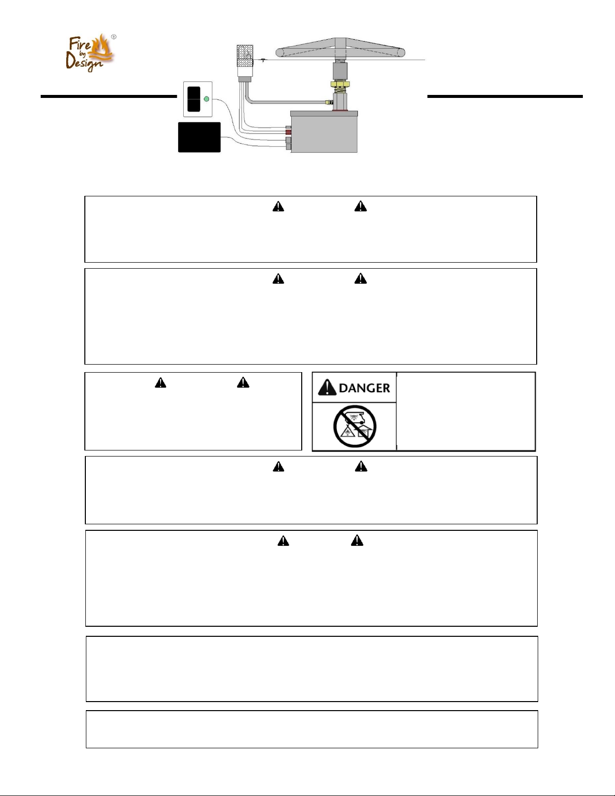
Battery Powered (3 AA)
All Weather Electronic Ignition
Owner’s Manual
Installation and Operation
Battery Powered
All Weather Electronic
Ignition System
Waterproof
Battery Pack
ON
OFF

2
AVERTISSEMENT
Une installation, un ajustement, une modification, une réparation ou un entretien inapproprié peuvent être la
cause de blessures ou de dommages. Veuillez lire attentivement les instructions d'installation, d'utilisation et
d'entretien avant d'installer ou de réparer ce matériel.
AVERTISSEMENT
Ne pas entreposer ni utiliser de l'essence ni d'autres vapeurs ou liquides inflammables dans le
voisinage de l'appareil, ni de tout autre appareil.
Une bouteille de propane qui n'est pas raccordée en vue de son utilisation, ne doit pas être entreposée dans
le voisinage de cet appareil ou de tout autre appareil.
DANGER
S'il y a une odeur de gaz:
1. Coupez l'admission de gaz de l'appariel.
2. Éteindre toute flamme nue.
3. Si l'odeur persiste, éloignez-vous de l'appareil et appelez immédiatement
le fournisseur de gaz ou le service d'incendie.
AVERTISSEMENT
Pour utilisation avec naturel ou propane ne gaz seulement
Aucun combustibles solides pour être utilisés avec ce système
MONOXYDE DE CARBONE
Cet appareil peut produire dumonoxyde de
carbone, un gaz inodore.
L’utililisation de cet appareil dans des espases clos
peut entrainer la mort.
Ne jamais utilizer cet appareil dans un espace clos
comme un vehicule de damping, une tente, une
automobile ou une maison.
AVERTISSEMENT
Pour utilisation
à l'extérieur seulement.
AVERTISSEMENT
Ne pas utiliser cet appareil s'il a été plongé, même partiellement, dans l'eau. Appeler un
technicien qualifié pour inspecter l'appareil et remplacer toute partie du système de commande et
toute commande qui a été plongée dans l'eau.
Proposition 65 Warning
Operating, servicing and maintaining this appliance can expose you to chemicals including
Carbon Monoxide and Lead which are known to the State of California to cause cancer, birth
defects or other reproductive harm. For more information go to www.Prop65Warnings.ca.gov

3
Table of Contents
Pilot Burner
Assembly
LP Air Mixer
(LP applications only)
Gas and Electrical Requirements
Page 4
Clearances
Page 4
Battery AWEIS System Components
Page 5
Installation
Page 5
Acceptable Media for Fire Features
Page 8
Installation of Media in Fire Features
Page 8
Operation
Page 9
Maintenance
Page 10
Replacement Parts
Page 11
Troubleshooting
Page 11

4
Gas Requirements
Fuel Type –Before making gas connections ensure appliance being installed is compatible with the
available gas type. Check the label on the appliance to confirm appliance gas type requirement.
Gas Pressure –Proper input gas pressures are required for optimum appliance performance.
Gas Pressure Requirements
Electrical Requirements
The Battery Powered All Weather Electronic Ignition System operates on 3 AA batteries
which are installed inside a Weatherproof Battery Pack that is included with the system.
Recommended Replacement Batteries: Energizer AA Ultimate Lithium
Pressure
Natural Gas
Propane
Minimum
3.5” W.C. / 1/8 psi
8.0” W.C. / 1/3 psi
Nominal
7.0” W.C. / ¼ psi
11.0” W.C. / 1/3 psi
Maximum
14.0” W.C. / ½ psi
14.0” W.C. / ½ psi
Clearances
WARNING –FIRE RISK
8 ft.
36 in.
2 in.
Clearance from Combustibles
Main Burner Clearances
Min. 6” Clearance
Max. 3” Below
Top of Bowl

5
Installation
Installation
Note: Installation should be done by a qualified service technician that is locally licensed.
1. In the photo at right there is a bowl with a gas riser
centered in the bowl. It is recommended to position the
gas riser in the center to ensure the fire ring is centered in
the bowl once installation is complete.
NOTE: Drainage MUST be provided in the bowl.
Drainage can be obtained by making holes in the bottom
or sides of the bowl or elevating the bowl off the
mounting surface by way of spacers or similar method.
2. Apply pipe dope/tape to the gas stub and thread the
AWEIS Ignition Control Box onto the gas riser as shown
in the photo at right.
NOTE: Leak Test –it is highly recommended to perform
a gas leak test at this point in the install. Turn on the gas
supply and then, using a soapy water solution spray the
bottom of the AWEIS where it is connected to the gas line
to ensure no leaks exist.
Gas
Stub
Battery Powered All Weather Electronic Ignition System Components
Low Profile Control Panel
Dimensions: 2” x 2.5”
Standard Control Panel
Dimensions: 4.5” x 4.5”
Ignition
Control Box
Control
Panel
Waterproof
Battery Pack
Pilot Burner
Assembly
6
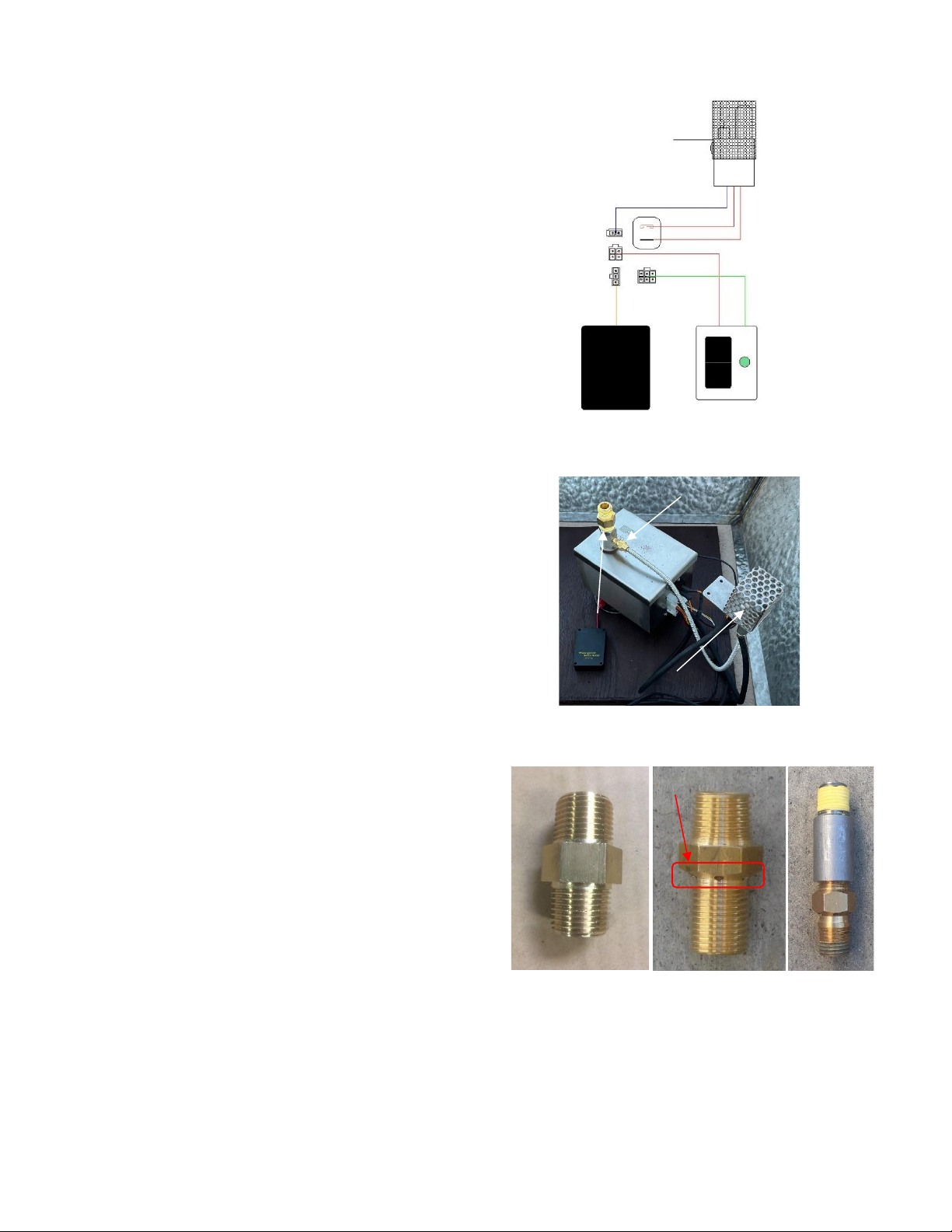
3. Electrical Connections: The illustration at right shows
where the various components plug into the front panel of
the Ignition Control Box. NO two connectors are the
same. This should prevent plugging a component into the
wrong connector. HOWEVER it is possible to plug a
connector into the correct receptacle incorrectly. When
plugging in a connector just a small amount of pressure is
required to plug it in. If excessive force is required, you
are probably plugging the connector in INCORRECTLY.
4. Connect the Pilot Burner Assembly gas line. This is a
¼” flare fitting so DO NOT apply Teflon tape or Pipe
dope to this fitting. Prior to tightening this fitting position
the Pilot Burner Cage such that when the burner pan is
installed the Pilot Burner Cage will be close to the Pilot
Burner opening in the burner pan. Now tighten the ¼”
flare nut on the Pilot Burner Gas Line.
Install the Main Burner Orifice. See directly below for a
description of the orifice that needs to be installed.
Natural Gas Orifice
LP Air Mixer
LP Air Mixer
Configured for Install
6 Air Holes
In Air Mixer
Main Burner Orifice: With every fire feature an orifice
MUST be installed between the outlet of the Ignition
Control Box and the burner. When the fuel type is
Natural Gas a Natural Gas Orifice is to be installed.
When the fuel type is Propane a LP Air Mixer is to be
installed. The noticeable difference between these two
orifices are the 6 Air Holes in the LP Air Mixer.
To ensure proper operation of the LP Air Mixer it must
be configured with a coupling and a pipe nipple as shown
in far-right photo. The Natural Gas orifice can be
installed without a coupling and pipe nipple.
Waterproof
Battery Pack
3AA
ON
OFF
SENSOR
SWITCH
BATTERY
IGNITER
LED/Bt
Pilot Burner
Assembly
Pilot Burner Assembly
Gas Line Connection
Main Burner
Orifice
Pilot Burner Cage
7
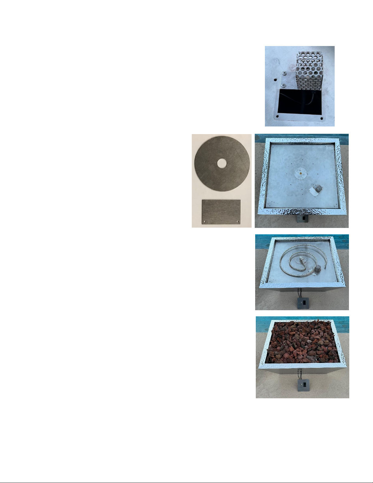
6. Install the Cover Plates. At right you see two plates
that came with the burner pan. The round plate is to be
installed over the Main Burner Orifice (as shown in
photo at far right). The plate does not need to be secured
to the pan with screws.
Next install the rectangular shaped cover plate over the
opening next to the Pilot Burner cage. This plate should
be secured to the pan using the stainless steel screws
supplied.
5. Install the Burner Pan, bring the Pilot Burner Cage up through the
Pilot Burner opening in the pan and secure to the pan using the stainless
steel screws supplied. See photo at right.
7. Install the Main Burner. It is recommended using either Teflon tape
or Pipe dope on the Main Burner orifice prior to installing the Main
Burner. Position the Burner such that a part of the burner is within 2”
of the Pilot Burner Cage.
8. Install acceptable media on top of the fire ring. “Acceptable”
media for fire features is covered on the next page.
“L” Shaped
Pilot Burner
Opening
8
Acceptable Media for Fire Features
List of Acceptable Media for Fire Features
Lava Rock (or other Igneous Rock) NO LARGER THAN 2” in diameter
Fireglass approved for use in fire features
Manmade stone for use in fire features (Refractory Material)
Installation Note
The use of media inside fire features is recommended due to the fact it enhances the look of the fire
feature but also improves its performance by forcing the gas emanating from the burner to mix as it
passes through the media. This ‘mixing’ of gases creates an even flame throughout the feature and helps
spread the flame from the Pilot Burner throughout the burner quicker than when there is no media.
Recommended thickness of the media above the burner element is NO MORE than 2”. Due to the
fact the Pilot Burner must be partially exposed to oxygen in order to ignite the pilot flame during startup
DO NOT COMPLETELY COVER THE PILOT BURNER. When installation of the media is complete
the top of the Pilot Burner Protective Cover should be visible.
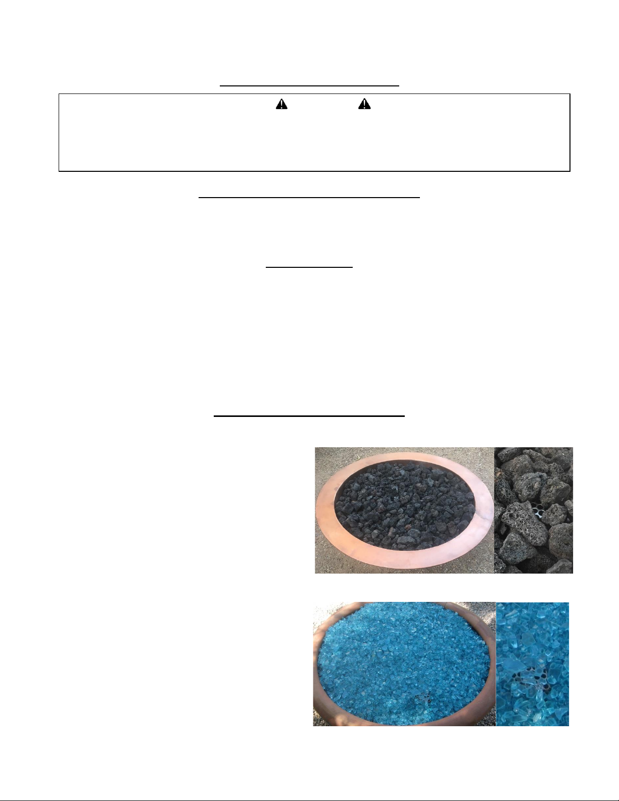
Installation of Media in Fire Features
Lava Rock
At right there are two pictures of the fire bowl after adding lava
rock. The size lava rock used in this feature is 2” in diameter.
The picture on the far right is a close up of the Pilot Burner.
Notice it is barely visible in either of the photos.
When using smaller lava rock you may not be able to cover it
as well due to the fact the smaller rock may “smother” the Pilot
Burner and prevent oxygen from getting to it.
WARNING
Do not use any other material as filler/topping media inside fire features other than those listed below.
Using improper media inside a fire feature could result in damage to property or
injury to persons nearby due to media ‘popping’ or ‘exploding’ due to heat
1” above ring
Fireglass
At right there are two pictures of the fire bowl after adding
fireglass. The size fireglass used in this feature is 1/2” in
diameter.
The picture on the far right is a close up of the Pilot Burner.
Notice it is barely visible in either of the photos.
When using smaller fireglass you may not be able to cover it as
well due to the fact the smaller rock may “smother” the Pilot
Burner and prevent oxygen from getting to it.

9
Illustrations showing Completed Installations
Operation
Fire Feature Start Up
1. Prior to turning appliance on visually inspect fire feature to ensure debris such as leaves or other
combustible material has not collected inside the feature which could burn and emit embers once the
fire feature is turned on. Also ensure any person standing close to the fire feature is aware you will be
turning the fire feature on prior to actually turning it on.
WARNING
Do NOT use this appliance if any part has been under water.
Immediately call a qualified service technician to inspect the appliance and to replace
any part of the control system and any gas control which has been under water.
WARNING
HOT –DO NOT TOUCH - SEVERE BURNS MAY RESULT - CLOTHING IGNITION MAY RESULT
-CAREFULLY SUPERVISE children in same area as the appliance.
-Alert children and adults to hazards of high temperatures.
-Clothing or other flammable materials should not be hung from the appliance or placed on or near the
appliance.
WARNING
The appliance should be inspected before use and at least annually by a qualified service technician.
Any guard or protective device removed for servicing must be replaced prior to operation.
Keep the appliance area clear and free from combustible materials, gasoline and other flammable vapors and liquids.
Pilot Burner
Assembly
Battery
Pack
Gas
Line
Illustration of Properly Installed AWEIS
(Natural Gas)
Natural Gas Orifice
Fire Ring / Burner
(Holes Facing Up)
Pilot Burner
Assembly
Burner Pan
Battery
Pack
Drain Hole
Switch
Illustration of Properly Installed AWEIS
(Propane)
Gas
Line
Ignition
Control Box
Air Mixer
Drain Hole
Coupling
Fire Ring / Burner
(Holes Facing Up)
Burner Pan
Drain Hole
Drain Hole
Ignition
Control Box
Switch

10
2. Turn fire feature on by turning the ON/OFF Switch to the ON position.
Sequence of Operation during Ignition
- Switch On: LED light begins flashing green indicating ignition is about to begin
- Gas Valve opens and spark ignition begins
- Ignition occurs almost immediately (assuming gas is present)
Fire Feature Shutdown
Turn fire feature off by turning the ON/OFF Switch to the OFF position.
1.
Maintenance
Prior to Each Use
1. Inspect for debris in Fire Feature –remove debris prior to use
Semi-Annually
1. Visually inspect Pilot Burner for debris/insect infestation (spider webs)
2. Visually inspect burner holes for debris/insect infestation
3. Clean either of the above as necessary using compressed air.
Annually
1. Visually inspect Pilot Burner for excess corrosion due to heat and moisture.
2. Turn fire feature on to ensure proper operation.
WARNING
Maintenance should be done by a qualified service technician.
The appliance should be inspected before use and at least annually by a qualified service technician.
WARNING
Ensure gas and power are shut off and appliance is cool before servicing.
WARNING
Any guard or protective device removed for servicing must be replaced prior to operation.
WARNING
If fire feature fails to turn off completely (small flames still visible)
Turn off gas supply using the manual gas shutoff.
11
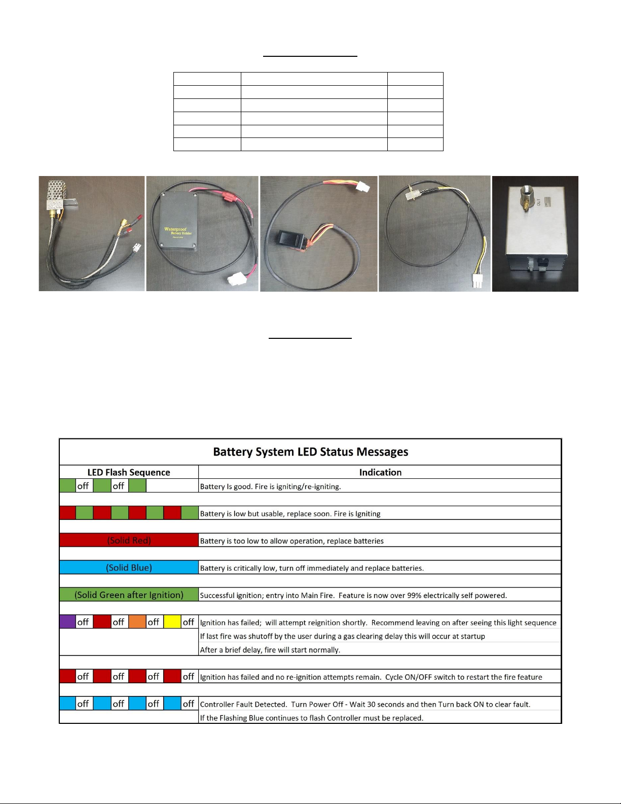
Troubleshooting
The LED light incorporated in the ON/OFF Switch is programmed to indicate failure modes within the
Battery Powered AWEIS System. Assuming there is a good gas source supplying gas to the feature
the system should operate normally. If it does not the indications from the LED will help troubleshoot
the problem. Below is a table showing the different LED Light Flash Sequences programmed into the
system. Use this table to diagnose what is going on with the system.
Item Letter
Part Name
Part #
A
Pilot Burner Assembly
BPBA
B
Battery Pack Assembly
BPack
C
Rocker Switch Assembly
BRS
D
LED Light Assembly
LED
E
Ignition Control Box
BICB
Replacement Parts
A
B
C
D
E
Table of contents
Popular Fireplace Accessories manuals by other brands


Town & Country Fireplaces
Town & Country Fireplaces 22150051 instructions

Travis Industries
Travis Industries 33 DVI installation instructions

Lopi
Lopi Hearthview 864 user manual

Lennox Hearth Products
Lennox Hearth Products LENNOX MPE-33R installation instructions

Dimplex
Dimplex DFP6776C install guide

Napoleon
Napoleon W175-0689 instruction manual

Travis Industries
Travis Industries 95400424 installation instructions

Osburn
Osburn ZERO CLEARANCE KIT installation instructions

Majestic
Majestic QUARTZPLA36IN installation instructions

Napoleon
Napoleon DBPO36 installation instructions

Dimplex
Dimplex SMP-130-E install guide

Empire Comfort Systems
Empire Comfort Systems LS50TINF installation instructions