This sensor must be installed in compliance with the control panel system
installation manual. The installation must meet the requirements of the Au-
thority Having Jurisdiction (AHJ). Sensors offer maximum performance when
installed in compliance with the National Fire Protection Association (NFPA);
see NFPA 72.
Before installing sensors, please read the system wiring and installation man-
ual thoroughly. This manual provides detailed information on sensor spac-
ing, placement, zoning, and special applications. Copies of these manuals are
available from Fire-Lite.
GENERAL DESCRIPTION
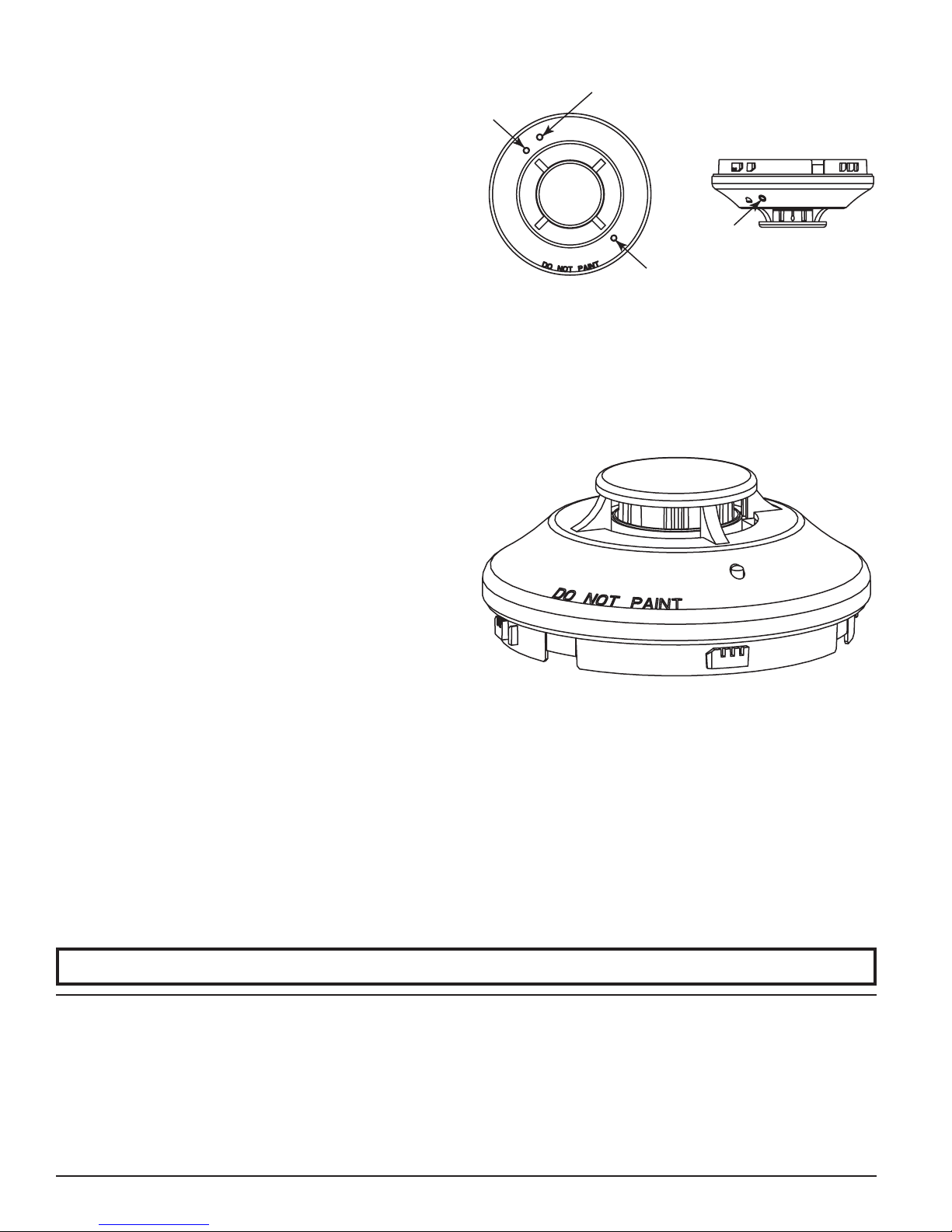
Models H355, H355R, and H355HT are intelligent sensors that utilize a state-
of-the-art thermistor sensing circuit for fast response. These sensors are de-
signed to provide open area protection with 50 foot spacing capability. For
installations which must comply with FM3210, see note below. Model H355 is
a fixed temperature sensor with 135° F fixed temperature alarm. Model H355R
is a rate-of-rise temperature sensor with 135° F fixed temperature alarm.
Model H355HT is a high temperature sensor with 190° F fixed temperature
alarm.
Two LEDs on each sensor light to provide a local, visible sensor indication.
Remote LED annunciator capability is available as an optional accessory (Part
No. RA400Z).
Models H355, H355R, and H355HT require compatible addressable com-
munications to function properly. Connect these sensors to listed-compat-
ible control panels only.
NOTE: Per FM3210
The H355 and H355HT are classified as fixed temperature thermal detectors:
A thermal detector that responds when the operating element of the detector
reaches a specified temperature. The actual temperature surrounding the sens-
ing element is often much greater than the rated temperature due to the ther-
mal lag.
The H355R is classified as a rate-compensated thermal detector: A thermal
detector that responds to a specified fixed temperature, regardless of the rate of
temperature rise.
WIRING GUIDE
All wiring must be installed in compliance with the National Electrical Code,
applicable local codes and the Authority Having Jurisdiction. Proper wire
gauges should be used. The installation wires should be color coded to limit
wiring mistakes and ease system troubleshooting. Improper connections will
prevent a system from responding properly in the event of a fire.
Remove power from the communication line before installing sensors.
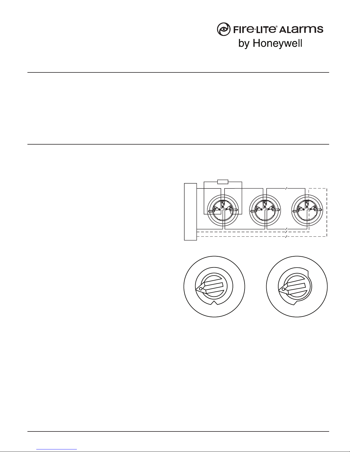
1. Wire the sensor base (supplied separately) per the wiring diagram,
see Figure 1.
2. Set the desired address on the sensor address switches, see Figure 2.
3. Install the sensor into the sensor base. Push the sensor into the base
while turning it clockwise to secure it in place.
4. After all sensors have been installed, apply power to the control unit and
FL-400-001 1 I56-3657-002R
I56-3657-002R
H355, H355R, and H355HT
Intelligent Plug-In Temperature Sensors
SPECIFICATIONS
Diameter: 6.1˝ (155 mm) installed in B350LP
Height: 2.0˝ (51 mm)
Weight: 4.8 ounces (137 gm)
Installation Temperature: –4°F to 100°F (–20°C to 38°C), H355 and H355R; –4°F to 150°F (–20°C to 66°C), H355HT
Operating Humidity Range: 10% to 93% Relative Humidity, Non-condensing
Mounting: B350LP flanged base
Voltage Range: 15 to 32 Volts DC Peak
Standby Current: 300 µA @ 24 VDC (one communication every 5 seconds with LED blink enabled)
LED Current: 6.5 mA @ 24 VDC
Fixed Temperature Rating: 135°F (57°C) H355 and H355R; 190°F (88°C) H355HT
Rate of Rise Detection: Responds to greater than 15°F/minute; H355R
INSTALLATION AND MAINTENANCE INSTRUCTIONS
activate the communication line.
5. Test the sensor(s) as described in the TESTING section of this manual.
FIGURE 1. WIRING DIAGRAM:
32
1
32
1
32
1
(–)
(+)
+-
UL LISTED COMPATIBLE
CONTROL PANEL
CAUTION: DO NOT LOOP WIRE
UNDER TERMINAL 1 OR 2.
BREAK WIRE RUN TO PROVIDE
SUPERVISION OF CONNECTIONS.
CLASS A OPTIONAL WIRING
REMOTE
ANNUNCIATOR
(–)
(+)
C0129-00
FIGURE 2:
TENS ONES
910
11
12
13
14
15
8
7
6
5
4
3
210
9
8
7
6
5
4
3
210
C0162-00
TAMPER RESISTANCE
The sensor base includes a tamper proof feature which when activated pre-
vents removal of the sensor without the use of a tool. See the installation
instruction manual for the sensor base for details in using this feature.
TESTING SENSITIVITY
Before testing, notify the proper authorities that the system is undergoing
maintenance, and will temporarily be out of service. Disable the system to
prevent unwanted alarms.
All sensors must be tested after installation and periodically thereafter. Test-
ing methods must satisfy the Authority Having Jurisdiction (AHJ). Sensors
One FireLite Place
Northford, CT 06472
Phone: 203.484.7161