Fireco Dorgard Pro User manual

Pro
Handbook
Compliance Made Easy
2019-07-17

Contents
Section 1: Pro system overview Page 1
Section 2: Survey and demo Page 7
Section 3: Installation Page 10
Section 4: Troubleshooting Page 13
Section 5: Maintenance Page 19
Section 6: Notes Page 20
Compliance Made Easy

The Pro Range provides a safe and legal way to hold open fire doors.
The Transmitter, which is connected to an alarm panel, will ensure all connected devices
release when an alarm is activated, preventing the spread of smoke and fire.
Part Number Part Name
885-3205 Fireco Transmitter
966-2075 Fireco Repeater
775-5231 Pro Timer
360-1551 Dorgard Pro Black
956-8278 Dorgard Pro White
338-0604 Freedor Pro
Pro system
overview
Pro system
overview
Page 1

The Transmitter is a radio control unit for the Pro system. Connected to a fire alarm relay,
it controls and monitors the system.
Fireco Transmitter
Power 8-30V AC or DC
Battery back-up Two x LR14 C-size batteries, capable of operating system
for upto 7 days
Triggers Volt free NC/NO/COM
Radio Frequency 433.050 MHz to 434.790 MHz
Range Survey dependant - typically 40-50m
Maximum System Capacity 50 Repeaters and 500 Pro Devices
Compliant to EN1155, EMC Directive, Radio Equipment Directive
Operating Temperatures -5 to +70C
• Casing Height: 180mm
• Width: 180mm
• Depth: 48.5mm
• Weight: 532g
180mm !
180mm
!
Radio
Fire
Power
Alert
Page 2
Pro system
overview

The Repeater extends the radio range from the Transmitter, allowing you to connect
more units over a greater distance. Up to 50 Repeaters may be used in any installation.
Fireco Repeater
Power 8-30V AC or DC
Battery back-up Two x LR14 C-size batteries, capable of operating system
for upto 7 days
Triggers Fireco Transmitter
Radio Frequency 433.050 MHz to 434.790 MHz
Range Survey dependant - typically 40-50m
Maximum System Capacity 8 Repeaters and 120 Pro Devices
Compliant to EN1155, EMC Directive, Radio Equipment Directive
Operating Temperatures -5 to +70C
• Casing Height: 180mm
• Width: 180mm
• Depth: 48.5mm
• Weight: 532g
!
180mm
180mm
!
Radio
Fire
Power
Alert
Page 3
Pro system
overview

!
A Pro Timer is a digital timer device which can be bound to a Transmitter or a Repeater.
It can be programmed to release all the devices further down the system for a set period
of time. There is also a manual override button which releases devices when pressed.
Pro Timer
Power 8-30v AC or DC
Battery life None
Triggers Programmed schedule on Digital Timer
Radio frequency 433.050 MHz to 434.790 MHz
Range Survey dependant - typically 40-50m
Maximum System Capacity 1 Parent Transmitter/Repeater
Compliant to EMC Directive, Radio Equipment Directive, CE marked digital
Timer (OEM)
Operating Temperatures -5 to +70
Radio
Fire
Power
Alert
Pro system
overview
• Casing Height: 180mm
• Width: 180mm
• Depth: 48.5mm
• Weight: 532g
!
180mm
180mm
Page 4

• Overall Height: 205mm
• Casing Height: 150mm
• Width: 195mm
• Depth: 45mm
• Weight: 700g
150mm
205mm
195mm
Dorgard Pro
Dorgard Pro is a fire door hold open device which can retain a fire door at any angle
of opening. When the fire alarm is activated, the Transmitter sends a radio signal to the
Dorgard Pro to release all doors, preventing the spread of smoke and fire.
Dorgard Pro
Power Two x LR14 C Size batteries
Battery life Five years
Triggers Fireco Transmitter 885-3205
Radio frequency 433.050 MHz to 434.790 MHz
Applicable door size Up to EN7 160Kg, 1600mm (with a floor plate)
Fire rating Dorgard has been tested to EN1634-1 on FD30 doorsets
exposed face and FD60 doorsets non-exposed face
Compliant to
EN1155, EN1634, EMC Directive, Radio Equipment Directive,
Critical (Cat A) BS7273-4, when hard wired to a Critical
(Cat A) system
Radio
Fire
Power
Alert
FR120M
Page 5
Pro system
overview

• Height: 65mm
• Height with arm: 150mm
• Length: 320mm
• Depth: 95mm
• Weight: 4.2kg
Freedor Pro takes the weight out of heavy fire doors, the free-swing feature allows you
to leave the door open at any position. When the fire alarm is activated, the Transmitter
sends a radio signal to the Freedor Pro to close all doors, preventing the spread of
smoke and fire.
Freedor Pro
Power 9V Alkaline battery pack
Battery life Five years
Triggers Fireco Transmitter
Radio frequency 433.050 MHz to 434.790 MHz
Applicable door size Up to EN3 60Kg, 950mm
Fire rating Freedor has been tested to EN1634-1 on FD30 doorsets,
exposed and unexposed faces
Compliant to EN1154, EN1155, EN1634-1 ETSI EN300 220-1,
ETSI EN300 220-2 EN50130-4:2011+A1:2014
Alert
Power
Fire
Radio
Pro system
overview
65mm
320mm
105mm
Page 6

1. Activate survey mode
Switch the Pro Demo & Site Survey Transmitter into
survey mode by flicking the switch on the base of
the Survey Transmitter to the right.
2. Binding
Dorgard Pro Depress the plunger on your
Demo Dorgard Pro. This will bind the two units
and enable you to survey a building.
Freedor Pro Push the button on the front of
unit. This will bind the two units together and
enable you to survey a building.
!
3. Surveying
Place the Survey Transmitter where you are proposing
to install the Fireco Transmitter. This should be within 2
metres of the fire alarm relay. Do not site Transmitters
within 1 metre of power sources or metal surfaces
(including Georgian wire glass).
Dorgard Pro
!
1
Surveying a
building prior to
installation
Survey and
demo
Page 7
Scan to watch our
technical support video
Repeat steps 3-4 from this position.
When survey is complete, switch transmitter to
the off position to conserve battery power.
To connect out of range devices, you will need to
install a repeater to extend the range.
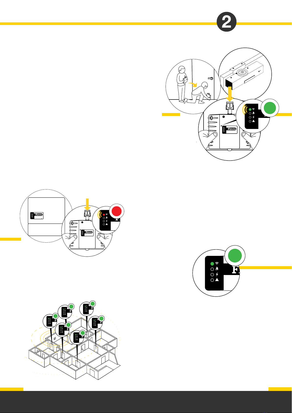
Dorgard Pro Place the Survey Dorgard Pro at the position
a Dorgard Pro is to be fitted. Hold it at the bottom of the
fire door.
Depress the plunger to get a radio reading. If the Dorgard
Pro is in range of the Survey Transmitter, the top LED of
the Dorgard Pro will show solid green for 4 seconds. If the
Survey Dorgard Pro is not in range, the top LED will show
red for 4 seconds.
Freedor Pro Place the Survey Freedor Pro at the position
a Freedor Pro is to be fitted. Fit to the correct side of the
door, using the adjustable bracket provided.
4. Repeater Location
To identify a suitable location for the new Repeater bring the
Survey Pro device closer to the Survey Transmitter until you are
again in range (confirmed by a green LED).
!Dorgard Pro
!Dorgard Pro
!Dorgard Pro
!Dorgard Pro
!Dorgard Pro
!Dorgard Pro
!
Survey and
demo
!
Press the button on the front of the Freedor Pro to get a radio reading.
If the Freedor Pro is in range of the Survey Transmitter the right LED of
the Freedor Pro will show solid green for 4 seconds. If the Survey
Freedor Pro is not in range the right LED will show red for 4 seconds.
Repeat this process for all of the doors you wish to survey.
Dorgard Pro
!
!Dorgard Pro
Dorgard Pro
!
!Do
Page 8

1. Activate demo mode
Switch the Pro Demo and Site Survey Transmitter
into demo mode by flicking the switch on the base
of the Survey Transmitter to the left.
Dorgard Pro Press down the plunger on the
Demo Dorgard Pro.
Freedor Pro Push the button on the front
of the unit.
2. Demonstration
Press the red demo button on the bottom of the
Survey Transmitter. The plunger will release on the
Dorgard Pro with Fire LED and sound a
warning tone.
The Freedor will show Fire LED and sound a
warning tone but nothing will happen mechanically
(ie keeper plate won’t switch between magnets).
Dorgard Pro
!
1
Carrying out
a product
demonstration
Survey and
demo
!
!
Dorgard Pro
!
!Dorgard Pro
Page 9

Dorgard Pro has 2 C cell batteries included and
connected. The battery compartment is accessed
by the screw on top of the unit.
Freedor Pro has a 9v battery pack included which
needs connecting at the installation point. Remove
the cover to access.
Power
Installation
Installation
Transmitter, Repeater and Timer
The Transmitter, Repeater and Timer are mains
powered using the 24v adapter. This can be
plugged into a socket using the plug top or wired
into a 1A fused spur using the kettle lead.
If powered direct, it requires any voltage between
8-30v AC or DC.
The transmitter monitors a normally closed
circuit and will release devices when the
circuit becomes open.
To connect, wire from the terminal block on the
transmitter to the corresponding contacts on
the fire alarm relay. It is possible to use just the
normally closed and common contacts if desired.
Refer to installation template.
8-30V ac/dc
Connecting
Transmitter to
fire alarm
C NO NC
FIRE ALARM
C NO NC
Page 10
Scan to watch our
technical support video

Binding
!!
DorgardPro
!DorgardPro
!
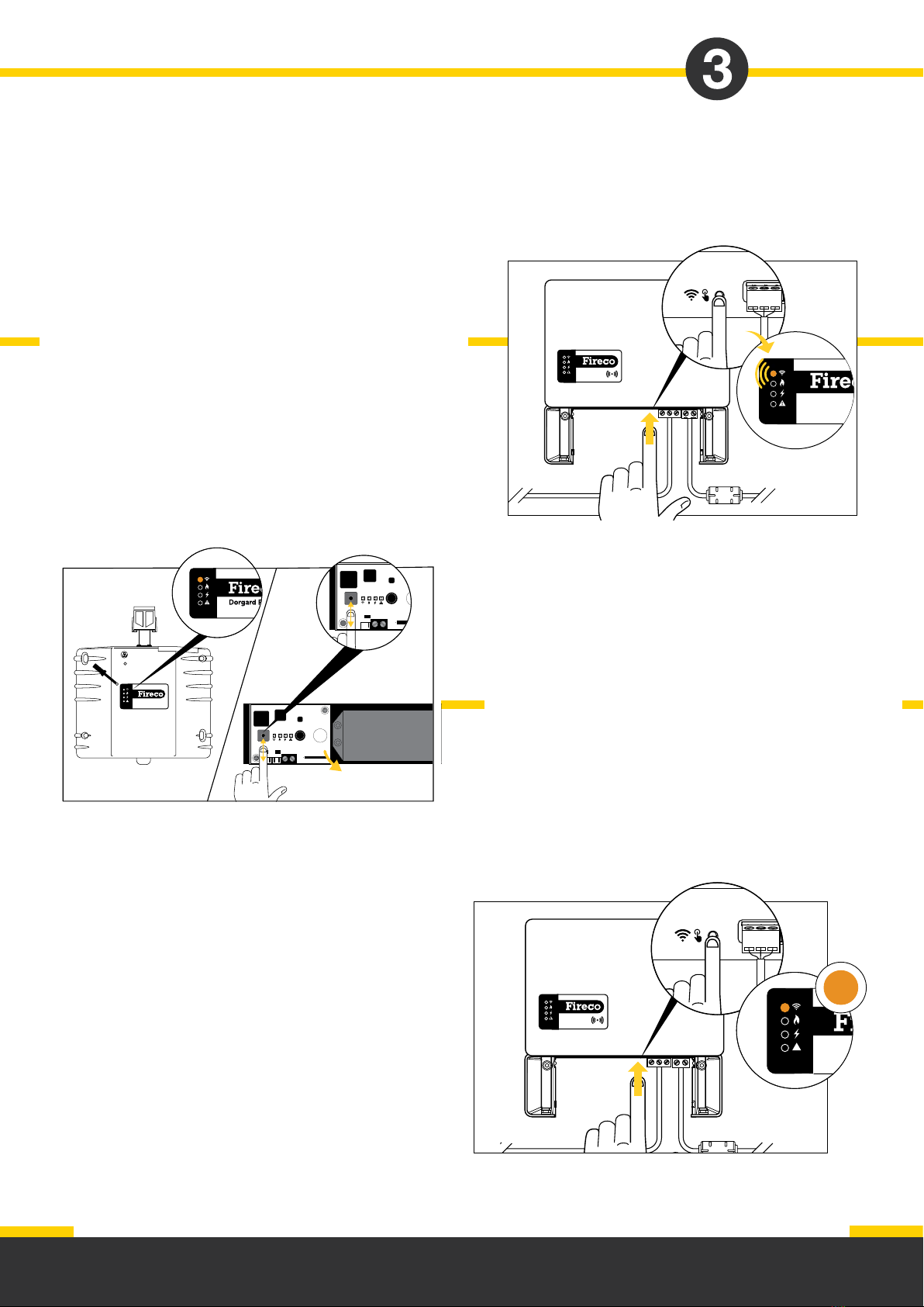
2. When the bind is successful, the radio LED will go
solid green on both parent and child for 4 seconds.
The child will no longer be in bind mode but the parent
remains in bind mode for an hour or until the bind
button is pressed again.
3. Should a repeater be required, it needs to be bound
to the parent in the same way as a pro device. When
successfully bound, it will carry out a radio channel
scan to select the strongest available channel.
The power LED will flash amber during scanning.
The repeater is now in parent mode and pro devices
and further repeaters can be bound to it.
NOTE
If during installation and set up the system identifies different versions of software in the devices, it will
trigger an over the air update, indicated by the parent displaying an amber alert LED. If successful, the
LED will turn green, if unsuccessful, it will turn red. To retry, press the bind button twice, repeat process
until successful.
1. To start the bind process, press the blue bind button
on the base of the Transmitter/Repeater (parent). The
radio LED will flash green, indicating in bind mode.
The pro device you wish to connect now needs to be
put into bind mode. This can be done by pressing the
bind button.
Dorgard Pro The bind button can be accessed through
the front casing using a 3mm screwdriver. The radio
LED will flash green to indicate in bind mode.
Freedor Pro The bind button is located on on the PCB,
accessed by removing the cover.
Information is communicated from the transmitter
to the Pro devices via radio. All devices need to be
bound together as a system.
This can be thought of as a family tree. The
transmitter is a parent device sending information.
Pro devices are children receiving information.
A repeater is both a parent and a child as it both
receives and sends information.
Installation
4
Page 11
Dorgard Pro
!
Unbinding
3. When the unbind is successful the radio LED
will go solid amber on both parent and child for
4 seconds. The child will no longer be connected
but the parent remains in unbind mode for 1 hour
or until the bind button is pressed again.
2. The pro device you wish to disconnect
now needs to be put into unbind mode.
This can be done by pressing and holding
the bind button.
On a Dorgard Pro it is accessed through the
front casing using a 3mm screwdriver.
The radio LED will flash amber to indicate
in unbind mode.
On a Freedor Pro this can be found on the
PCB, accessed by removing the cover.
4
Installation
If it is necessary to bind a child device to a
different parent you will first need to unbind it.
1. To start the unbind process, press and hold
the blue bind button on the base of the parent
Transmitter/Repeater. The radio LED will flash
amber indicating in unbind mode.
Dorgard Pro
!
4
!
Page 12

Troubleshooting section
Section 1: Failing to bind Page 14
Section 2: Red radio LED and red alert on device Page 16
Section 3: Factory reset Page 17
Section 4: Dorgard Pro is marking the floor Page 18
Compliance Made Easy
Scan to watch our
technical support videos
Page 13

Failing
to bind
Pro devices
State
The Pro devices will indicate failure to bind by
showing the radio LED and alert LED as red.
It will then take itself out of bind mode.
Fix
If problem persists it is likely the Pro device is out of range. We recommend you carry out a site
survey - see section 2.
It may be necessary to re-site the Transmitter or Repeater closer to the Pro device;
OR bind the Pro device to a different Repeater;
OR add another Repeater to your system to increase the coverage.
Check
1. Check that the Transmitter or Repeater to which
you want the Pro devices to bind is in bind mode.
The Transmitter or Repeater will be flashing its radio
LED green.
2. While the Transmitter or Repeater is in bind
mode, push the bind button on the Pro device.
The Pro device will flash its radio LED green and retry
binding to the Transmitter or Repeater.
Dorgard Pro
!
!Dorgard Pro
4
Troubleshooting
Page 14

Repeater
State
The Repeater is still flashing its top radio LED
green 1 minute after the bind button on the base
of the Repeater has been pressed down.
Check
Check that the Transmitter or parent Repeater is in
bind mode, indicated by the radio LED flashing green.
Press the bind button on the Repeater. If the radio
LED stops flashing and turns solid green for 4
seconds, it has bound to the Transmitter or
parent Repeater.
Fix
If problem persists, it is likely the Repeater is out of
range. We recommend you carry out a site
survey - see section 2.
OR move the Repeater closer to the Transmitter or parent Repeater;
OR bind the Repeater to a different Repeater;
OR add another Repeater to your system to increase the coverage.
4
!
Dorgard Pro
!
!
Troubleshooting
Page 15

Red radio LED
and red alert
on device
State
This is indicating that the device has lost
communication with its parent Transmitter/
Repeater. The device will be in a fail safe condition.
If the lost device is a Repeater, any connected
devices will also fail to safe.
Troubleshooting
Fix
The fault should be resolved at the primary device where the fault was detected. If no fault with the
parent and the fault is isolated to the device, it may be caused by loss of signal due to range.
Fix
Carry out a site survey to ensure sufficient range
where the device is located, it may be necessary to:
Re-site Transmitter or Repeater;
OR bind the device to different Repeater;
OR add another Repeater to the system to
increase range.
Check
Check the state of the parent Transmitter/Repeater of
the lost device for power and/or faults. If the system has
multiple Repeaters, it may be necessary to check all parents
to identify the primary source of the fault.
!
Dorgard Pro
!
!
Page 16

30-60s
Factory reset
Dorgard Pro
!x3
Performing a factory reset is a way of returning the device
to its original system state by erasing all of the information
stored.
The reset restores the device to the original manufacturer
settings. Any connected devices will be unbound.
Troubleshooting
Dorgard Pro
Undo battery compartment and pull up to
disconnect power. Hold down the bind button
whilst reconnecting power until it beeps 3 times.
Freedor Pro
Remove the cover and disconnect the battery.
Hold down the bind button whilst reconnecting
the battery until it beeps 3 times.
Transmitter & Repeater
Disconnect the power and remove one of the
back-up batteries. Hold down the blue bind button
whilst reconnecting the power until it beeps 3
times. Replace the back-up battery.
Page 17
x3
Scan to watch our
technical support video

Dorgard Pro
is marking
the floor
Dorgard Pro has an anti-drag feature. When
activated if the door is pulled, the Dorgard Pro
will release allowing the door to close.
To activate contact Fireco Technical Support team
on +44(0)1273 320650 who will provide you with
the required sound file.
Troubleshooting
Page 18
Scan to watch our
technical support video
Other manuals for Dorgard Pro
1
This manual suits for next models
10
Table of contents
Other Fireco Door Opening System manuals


Popular Door Opening System manuals by other brands

RIB
RIB ACG9416 instruction manual

Automatic Technology
Automatic Technology Dominator Tempo ATS-2AM instruction manual

Lamp
Lamp FM150PRO installation manual

CornellCookson
CornellCookson FS-500EP Series Installation instructions and operation manual

Kaba
Kaba SLA operating instructions

DITEC
DITEC DOD Technical manual


