Omron Sti F3SJ-AM P Series Operating and maintenance instructions

Multi-beam Safety Sensor
F3SJ-AM□P□□□ Series
© OMRON Corporation 2017-2020 All Rights Reserved.
Original instructions
Quick Installation Manual
Relevant manual Cat. No.
Multi-beam Safety Sensor F3SJ-AM Series
User's Manual SCHG-716
3126477-9B

1F3SJ-AM
Quick Installation Manual
Introduction
Thank you for purchasing the F3SJ-AM
P
Series Multi-beam Safety Sensor (hereinafter referred to as the "F3SJ-AM").
This document is a brief description from wiring to pre-operation checklists / maintenance checklists of F3SJ-AM.
For details, download and read F3SJ-AM user's manual from Omron's website. If you Login / Signup, you can
download the PDF of the Manual.
http://www.omron.com.au/products/family/1581/download/manual.html
Table of Contents
1. What is Included ................................................................................................................................ 1
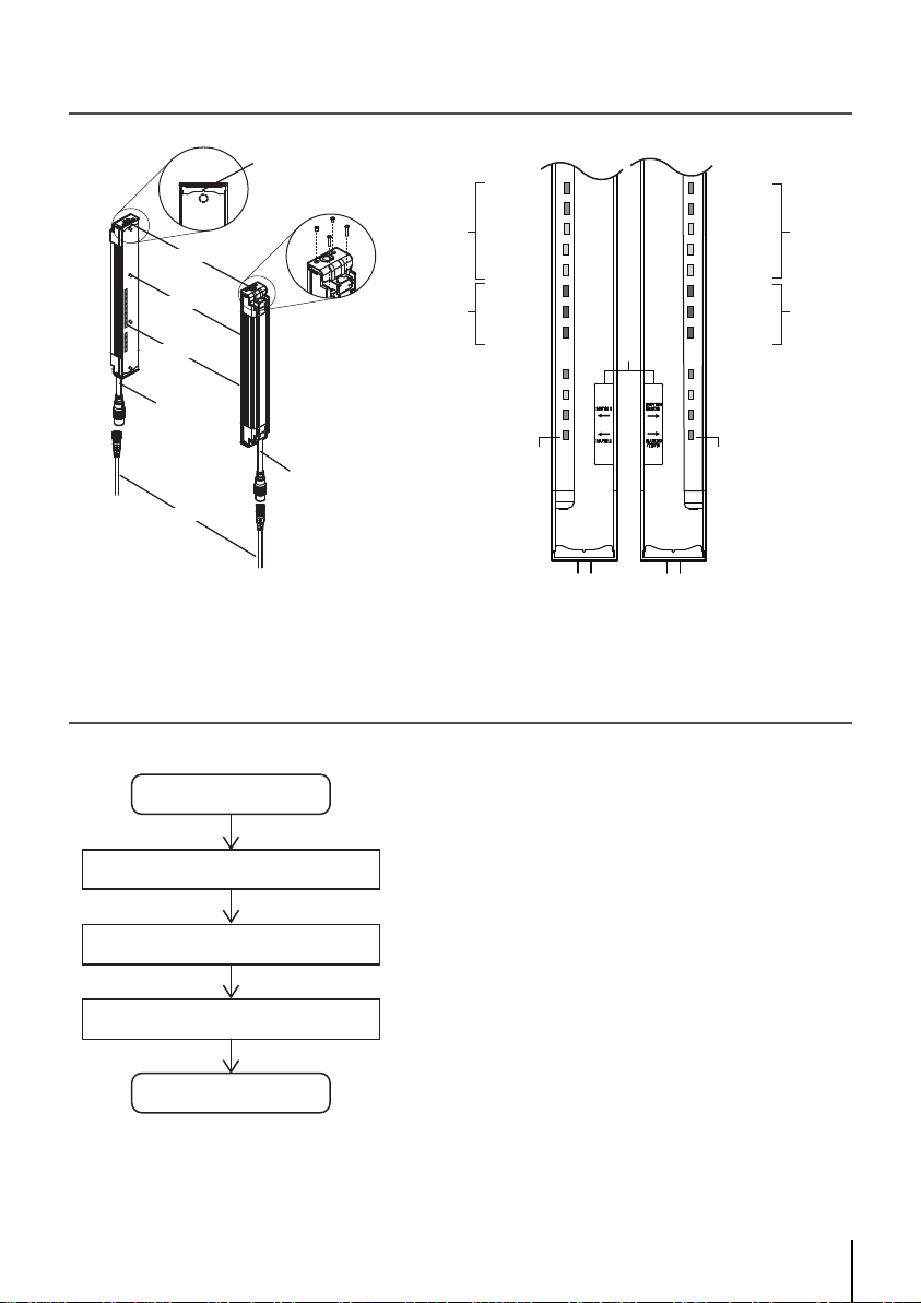
2. System Components .........................................................................................................................2
3. Light Curtain Setup Flow ...................................................................................................................2
4. Function Selection Flow Chart .......................................................................................................... 3
5. Mounting and Beam Alignment .........................................................................................................4
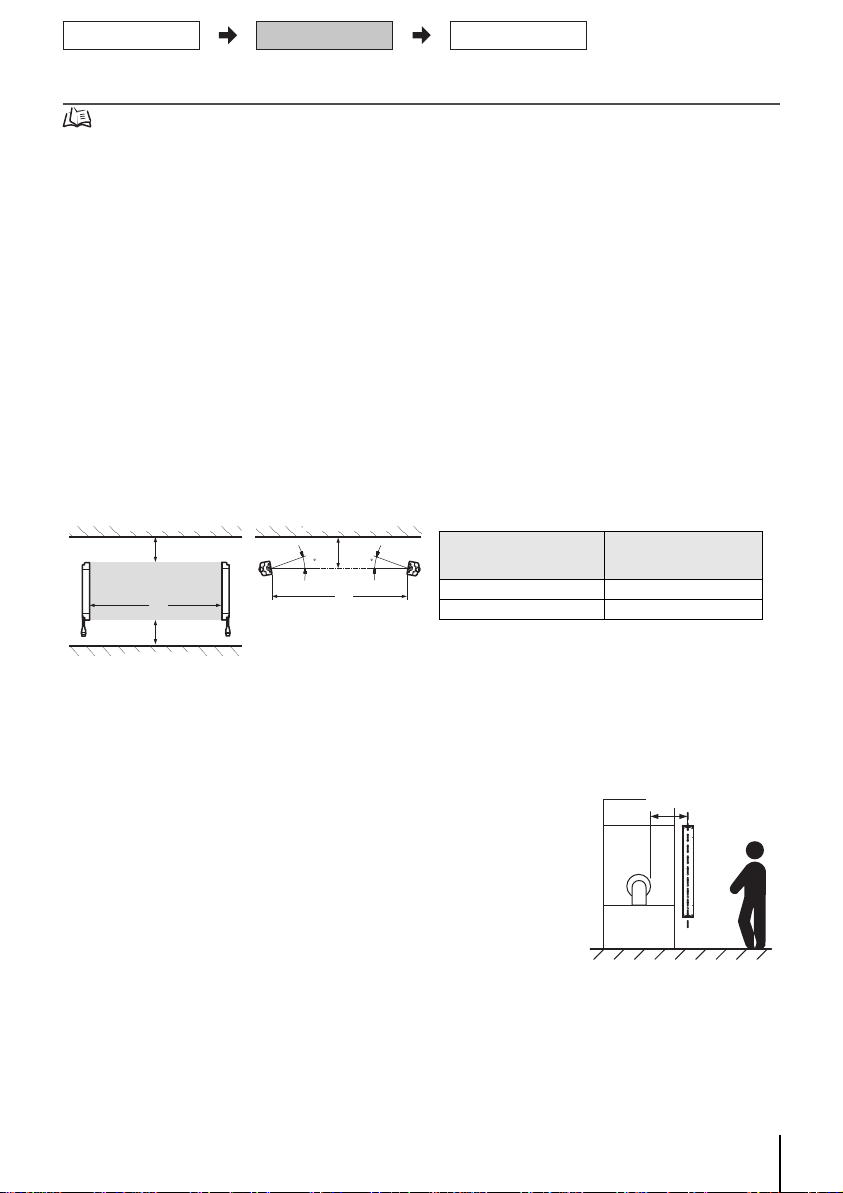
5-1. Mutual Interference Prevention .................................................................................................4
5-2. Distance from Reflective Surfaces ............................................................................................4
5-3. Safety Distance .........................................................................................................................4
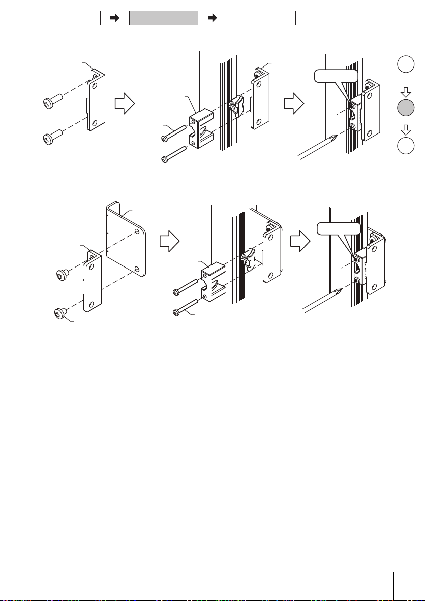
5-4. External dimensions to attach the brackets included in the product (F39-LJ1/F39-LJ3) ..........5
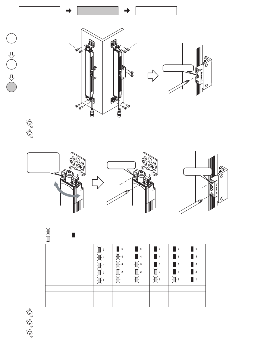
5-5. Mounting and Beam Alignment .................................................................................................7
6. Pre-Operation Checklists / Maintenance Checklists........................................................................10
Suitability for Use/Contact Information ................................................................................................13
1. What is Included
For ratings/specifications, input/output circuit, LED indicator status and troubleshooting, refer to F3SJ-AM Series User's Manual.
Product Quantity
F3SJ-AMP main unit Emitter x 1, Receiver x 1
For details, refer to F3SJ-AM series user's manual.
4
The number of brackets to be included in the product depends on the model.
F3SJ-AM2P300: Not included
F3SJ-AM3P300: 1 set included
F3SJ-AM4P300: 1 set included
F3SJ-AM2P400: Not included
F3SJ-AM3P400: 1 set included
F3SJ-AM4P400: 2 sets included
F3SJ-AM2P500: Not included
Error Mode Label 1
Operation Manual 2
Quick Installation Manual (this document)
1
Functional Settings
*1 Vs here means the voltage value under use environment.
Function Setting
External Test Enabled when 9V to Vs*1 applied
Interlock
Switching between manual reset mode and auto reset mode is available by wiring
External Device Monitoring (EDM)
Switching between enable/disable is available by wiring
Auxiliary Output
Auxiliary Output 1: Control Output Information (NOT output mode: Enabled)
Auxiliary Output 2: Total Power ON Time Information (ON when 30000 hours passed)
Functional settings can be changed by the setting tool (option)
External Indicator
Enabled when External indicator set (F39-A01P□-PAC)/
Universal indicator cable (F39-JJ3N) attached
In case of Basic System
External Indicator 1: Control Output Information (NOT output
mode: Enabled)
External Indicator 2: Error/Lockout Information
In case of Muting System
External Indicator 1: Muting/Override Information
External Indicator 2: Muting/Override Information
Muting Enabled when muting Key Cap F39-CN6 attached
Override Enabled when muting Key Cap F39-CN6 attached
Top/Bottom
Mounting Bracket
Intermediate
Mounting Bracket

2
F3SJ-AM
Quick Installation Manual
2. System Components
3. Light Curtain Setup Flow
Emitter
Receiver
Cap
Indicator
Beam
Extension cable
Beam center-line mark
Connection cable (Grey)
Connection cable
(Black)
To attach or detach the
cap and power cable,
remove 4 screws shown
above.
4. Interlock indicator (Yellow)
3. Power indicator (Green)
2. Error mode
indicator
1. Incident light level
indicator
EMITTER
LEVEL
POWER
ERROR ERROR
INTLK
EDM
TEST
5
4
3
2
1
C
B
A
5
4
3
2
1
C
B
A
RECEIVER
LEVEL
OFF
ON
*1
LEVEL-5 (Green)
LEVEL-1 (Orange)
LEVEL-2 (Orange)
LEVEL-3 (Orange)
LEVEL-4 (Green)
ERROR-
C
(Red)
ERROR-B (Red)
ERROR-A (Red)
LEVEL-1 (Orange)
LEVEL-2 (Orange)
LEVEL-3 (Orange)
LEVEL-4 (Green)
LEVEL-5 (Green)
ERROR-B (Red)
ERROR-
A
(Red)
ERROR-C (Red)
1. Incident light
level indicator
2. Error mode
indicator
8. ON-state indicator (Green)
7. OFF-state indicator (Red)
Emitter Receiver
5. External device monitoring indicator (Green)
[Muting input 1 indicator]
6. Test indicator(Green)
[Muting input 2 indicator]
9. Not used (Green)
[Muting error indicator]
10. Not used (Green)
[Test indicator]
A set of square brackets, [ ], indicates
name of an indicator under muting system.
*1 This label comes with the F39-CN6 key
cap for muting. Affix this label when a
keycap is used.
MULTI
-BEAM MULTI
-BEAM
Setup
Function Selection
Mounting/Beam Alignment
Pre-Operation Checklists/Maintenance Checklists
Done
. . . page 3
. . . page 4
. . . page 10

3F3SJ-AM
Quick Installation Manual
4. Function Selection Flow Chart
Required system configuration depends on functions to be used. Use the following flow chart to determine
the system.To change the functional settings, use the setting tool (option).
For configuration and setting changes to use the muting function, refer to F3SJ-AM series user's manual.
Using Muting Function Basic System
Muting System *1
NO
YES
*1 Muting Key Cap (F39-CN6) is necessary.
Pre-Operation Checklist /
Maintenance Checklists
Mounting/Beam Alignment
Function Selection

4
F3SJ-AM
Quick Installation Manual
5. Mounting and Beam Alignment
For brackets other than those included in the product (F39-LJ1/F39-LJ3) as well as external dimensions and mounting,
refer to F3SJ-
AM series user's manual.
5-1. Mutual Interference Prevention
■Series Connection
Series connection can prevent mutual interference when multiple sensors are used. Up to 4 sets, 400 beams,
can be connected. The emission of series-connected F3SJ-AM is time-divided, so mutual interference does
not occur and safety is ensured.
■No Connection
Mutual interference is prevented in up to 3 sets, using interference light avoidance algorithm. If 4 or more
sets of F3SJ-AM are installed and are not connected to each other, arrange them so that mutual interference
does not occur. If 2 sets are installed near each other, reflection from the surface of the F3SJ-AM may cause
mutual interference. When mutual interference occurs, the safety outputs are turned OFF in a moment or the
F3SJ-AM enters lockout. Combining countermeasures 1 to 4 shown below is effective.
1. Install a physical barrier between 2 sets
2. Alternate the direction of emission between 2 sets (alternation) If 2 sets are installed near each other,
reflection from the surfaces may cause mutual interference. For such a case, it can be improved by
reducing operating range through the setting tool (see Step 3).
3. Reducing operating range (setting change by the setting tool is required)
4. Keep sufficient distance between the F3SJ-AMs so that mutual interference does not occur
5-2. Distance from Reflective Surfaces
Install the sensor system at distance D or further from highly reflective surfaces such as metallic walls, floors,
ceilings, or workpieces, as shown below.
5-3. Safety Distance
How to calculate the safety distance specified by International Standard ISO 13855(European standard EN
ISO 13855)(Reference)
■If a person approaches the detection zone of the F3SJ-AM perpendicularly
S = K x T + C . . . Formula (1)
• S: Safety distance
• K: Approach speed to the detection zone
• T: Total response time of the machine and F3SJ-AM
• C: Additional distance calculated by the detection capability of the F3SJ-AM
Calculate by using Formula (1) with K = 1,600mm/s
and C = 850mm:
S = 1,600mm/s x (Tm + Ts) + 850 . . . formula (4)
S = Safety distance (mm)
Tm = Response time of the machine (s)
Ts = F3SJ-AM's response time from ON to OFF (s)
Please refer to the user's manual for calculation of following safety distance.
■Possible circumventing by reaching over the detection zone
■How to calculate the safety distance specified by American standard ANSI B11.19(reference)
L
D
D
L
D
55
Detection zone
Emitter Receiver Emitter Receiver
Reflective ceiling
Reflective floor
Reflective surface
Distance between an emitter
and a receiver
(operating range L)
Allowable installation
distance D
For 0.2 to 3m 0.13m
For 3m or more L/2 x tan5 ° = L x 0.044 (m)
Hazard
Safety distance (S)
Mounting/Beam Alignment
Function Selection
Pre-Operation Checklist /
Maintenance Checklists

5F3SJ-AM
Quick Installation Manual
5
-4. External dimensions to attach the brackets included in the product (F39-LJ1/F39-LJ3)
■Dimensions (Check position)
2-Top/bottom mounting brackets
2-Mounting holes
2-Mounting holes
M12 Waterproof connector
Intermediate mounting
bracket
2-Mounting holes
4-Mounting holes
Beam
3.75
6.25
E
13.75 B
A
30
9
42
53
22
31
6.5
20
5.5 30
C37
16.5
5.5
7
EB
22
42
4-M5
24
30043
1
15
6
26
46
10
2-M5
D
20
Beam center line mark
(13.75)
3
[ Unit : mm ]
[Backside mounting]
Dimensions A to E and P
Model name Number of beams A B C D E P Number of intermediate
mounting brackets
F3SJ-AM2P300 2 394 366.5 320 300 - 300 0
F3SJ-AM3P300 3 694 666.5 620 600 B/2 300 1
F3SJ-AM4P300 4 994 966.5 920 900 B/2 300 1
F3SJ-AM2P400 2 494 466.5 420 400 - 400 0
F3SJ-AM3P400 3 894 866.5 820 800 B/2 400 1
F3SJ-AM4P400 4 1294 1266.5 1220 1200 B/3 400 2
F3SJ-AM2P500 2 594 566.5 520 500 - 500 0
Check
position
Step1
Mount
Step2
Align
beams
Step3
Mounting/Beam Alignment
Function Selection
Pre-Operation Checklist /
Maintenance Checklists

6
F3SJ-AM
Quick Installation Manual
■Dimensions (Check position)
2-Top/bottom
mounting brackets
2-Mounting holes
30
P
31
5
C
10
37
35
31
15
EB
20
2-M5
4-M5
3.75
6.25
B
E
13.75
15
A
24
9
10
53
30
20
16.5
6.5
30043
36
43
5.5
6
51
53
D
Beam center line mark
Intermediate
mounting bracket
2-Mounting holes
4-Mounting holes
M12 Waterproof connector
Beam
5.5
(13.75)
[ Unit : mm ]
[Side mounting]
For dimensional drawing of mounting brackets other than those included in the product (F39-LJ1/F39-LJ3), refer to F3SJ-AM
series user's manual.
Dimensions A to E and P
Model name Number of beams A B C D E P Number of intermediate
mounting brackets
F3SJ-AM2P300 2 394 366.5 320 300 - 300 0
F3SJ-AM3P300 3 694 666.5 620 600 B/2 300 1
F3SJ-AM4P300 4 994 966.5 920 900 B/2 300 1
F3SJ-AM2P400 2 494 466.5 420 400 - 400 0
F3SJ-AM3P400 3 894 866.5 820 800 B/2 400 1
F3SJ-AM4P400 4 1294 1266.5 1220 1200 B/3 400 2
F3SJ-AM2P500 2 594 566.5 520 500 - 500 0
Check
position
Step1
Mount
Step2
Align
beams
Step3
Mounting/Beam Alignment
Function Selection
Pre-Operation Checklist /
Maintenance Checklists

7F3SJ-AM
Quick Installation Manual
5-5. Mounting and Beam Alignment
1. Attach the top/bottom brackets.
Tightening with torque exceeding the recommended value too much may lead to a failure.
2. Attach the intermediate mounting brackets (2) and (3).
For mounting positions of the intermediate mounting brackets (2) and (3), refer to 5-4 E dimensions.
Fit in the slot of the convex block
Mounting screw
(M5x20)
Top/bottom
mounting
bracket (2)
Mounting screw
(M3x8)
Top/bottom
mounting
bracket (3)
Top/bottom mounting
bracket (1)
Tighten lightly
(Recommended tightening torque: 2.3N•m)
Insert the tab in the slot
Mounting
screw
(M3x10)
Intermediate
mounting
bracket (2)
Intermediate
mounting
bracket (3)
Attach the bracket so that the tab of the bracket
in the dotted circle should be on the back end.
Tighten
lightly
Check
position
Step1
Mount
Step2
Align
beams
Step3
Mounting/Beam Alignment
Function Selection
Pre-Operation Checklist /
Maintenance Checklists

8
F3SJ-AM
Quick Installation Manual
3. <On back end mounting> Attach the intermediate mounting brackets (1) and (4).
4. <On side mounting> Attach the intermediate mounting brackets (1) and (4) as well as the side-mounting
intermediate mounting bracket.
Intermediate
mounting
bracket (1)
Intermediate
mounting
bracket (4)
Mounting screw
(M4x25)
Intermediate
mounting
bracket (1) Tighten lightly
(Recommended tightening torque: 2.3N•m)
Intermediate
mounting
bracket (1) Intermediate
mounting
bracket (4)
Mounting screw
(M4x25)
Intermediate mounting
bracket for
side mounting
Mounting screw
(M5x10)
Tighten lightly
Check
position
Step1
Mount
Step2
Align
beams
Step3
Mounting/Beam Alignment
Function Selection
Pre-Operation Checklist /
Maintenance Checklists

9F3SJ-AM
Quick Installation Manual
5. Fix the unit on the wall.
Tightening with torque exceeding the recommended value too much may lead to a failure.
Wall-mounting screws are not included.
6. Align beams based on the indicators.
Please refer to instruction sheet about wiring examples.
■Display Patterns of the Incident Light Level Indicator
Operation is possible with incident light level of 100% or more, but to ensure stability, operate when all incident light level
indicators.
Please do not tighten each screw one by one. Fully tighten all of them in a balanced manner at all places.
The angle adjustment range of mounting bracket F39-LJ3 is +/-10 degrees.
Wall-mounting screw (M5)Wall-mounting screw (M5)
(Recommended tightening torque: 0.54N•m)
Backside mounting Side mounting
Tighten securely
(Recommended tightening torque: 0.54N•m) (Recommended tightening torque: 1.2N•m)
Tighten securely
Tighten securely
Align the unit to the
center of the angle
where five (5) light
intensity level
indicators turn ON
incident light level indicator
FFOFFOFFONONONOSafety Output
Incident light level 170% or
higher
Less than
170%
~
130%
Less than
130%
~
100%
Less than
100%
~
75%
Less than
75%
~
50%
Less than
50%
ON OFF
Check
position
Step1
Mount
Step2
Align
beams
Step3
Mounting/Beam Alignment
Function Selection
Pre-Operation Checklist /
Maintenance Checklists

10
F3SJ-AM
Quick Installation Manual
6. Pre-Operation Checklists / Maintenance Checklists
After wiring, mounting and beam alignment are done, check the operation of the F3SJ-AM.
Pre-Operation Checklists
After installation, the highest level administrator must use the following checklist to verify the operation, plac-
ing a check mark in each of the boxes.
■Checklists
- Installation Condition Check
□The machine itself does not prevent the operation of safety functions such as stopping.
□The hazardous part of a machine cannot be reached without passing through the detection zone of the
F3SJ-AM.
□The system is configured so that the F3SJ-AM can always detect a worker who is working in the hazard-
ous zone.
□The interlock reset switch is installed in a location that provides a clear view of the entire hazardous zone
and it cannot be activated from within the hazardous zone.
□Safety distance has been calculated. Calculated distance: S = ( )mm
□The actual distance is equal to or greater than the calculated distance. Actual distance = ( )mm
□Reflective surfaces are not installed in prohibited zones.
□Not installed in a reflective configuration.
□When muting function is used, a muting sensor must be installed so that muting state should not occur
when a human body enters a detection zone of F3SJ-AM by mistake.
□When muting function is used, a muting sensor must be installed so that muting state should not occur
when a human body enters a hazardous zone of a machine.
□When muting function is used, muting state can be checked from where a worker operates or adjust the
machine.
□A muting sensor consists of 2 independent devices.
□It is not used in flammable or explosive atmosphere.
- Wiring Check Before Power Is Turned ON
□When the power supply unit is connected to multiple devices, the power supply unit must have tolerance
against total rated current of the devices.
□The power supply unit is a 24 VDC unit that conforms to the EMC Directive, Low-voltage Directive, and
output holding specifications.
□The power supply polarity is not connected in reverse.
□Emitter/receiver cables are properly connected to the respective emitters/receivers.
□Double insulation is used between I/O lines and the hazard potential (commercial power supplies, etc.).
□Outputs are not short-circuited to +24V line.
□Loads are not connected to the +24V line.
□All lines are not connected to commercial power source.
□F3SJ-AM's power supply connector and series connection connector must not be attached upside down.
□Model of emitter and receiver must be the same.
□When 2 or more sets of F3SJ-AM are used, series connection is made or mutual interference prevention
measures are taken.
□When 2 or more sets of F3SJ-AMs are used in series connection, PNP output type and NPN output type
must not be connected.
□A secondary sensor farthest from its power supply has either of the followings:
• Cap
• Key cap for muting
• Muting lamp (set of lamp and cable)
□Neither connector, cap, or bracket must be loose.
□Auxiliary outputs 1 and 2, and external indicator outputs 1 and 2 must not be used as safety output.
□Power supply's 0V must be grounded.
□Wiring must not be bent, cracked, nor damaged.
-Operation Check While the Machine Is Stopped
□A checkup detection object (opaque bar or plate) with width of 10mm or wider must be provided by a
user.
Mounting/Beam Alignment
Function Selection
Pre-Operation Checklist /
Maintenance Checklists

11 F3SJ-AM
Quick Installation Manual
□When a checkup detection object is inserted along the beam center line mark ( mark ) so that it should
interrupt beams, the sensor must be under interrupted status (all 5 incident light level indicators turn OFF,
and the OFF output indicator turns ON). Detection must be checked for 3 points shown below:
• Right in front of an emitter (A)
• Right in front of a receiver (B)
• In the middle of an emitter and a receiver (C)
□When the external test function is used:
The OFF-state indicator turns ON when the test input line is short-circuited to 9V to Vs.
□When the external device monitoring function is used:
When the F3SJ-AM is blocked and the external device monitoring input terminal is open, it enters a lock-
out state.
□When the start interlock function is used:
After the F3SJ-AM is turned ON, the OFF-state indicator remains turned ON, even if the F3SJ-AM is
receiving light. The reset switch input turns ON the ON-state indicator.
□When the restart interlock function is used:
While the ON-state indicator is ON, the OFF-state indicator remains turned ON, even when the F3SJ-AM
is blocked and then receives light again. The reset switch input turns ON the ON-state indicator.
□When muting function is used, minimum muting time limit required must be set.
□When muting function's operation mode is exit only muting mode, minimum muting waiting time required
must be set.
□Under muting state, a signal that indicates muting state must be output from either of the followings:
• External Indicator 1 or 2
• Auxiliary Output 1
□When override function is used, minimum override time limit required must be set.
□Under override state, a signal that indicates override state must be output from either of the followings:
• External Indicator 1 or 2
• Auxiliary Output 1
-Checking that Hazardous Parts Stop While the Machine Operates
□The hazardous parts stop immediately when a checkup detection object interrupted any beam at 3 posi-
tions: "directly in front of the emitter", "directly in front of the receiver", and "between the emitter and
receiver".
□The hazardous parts remain stopped as long as the checkup detection object keeps interrupting a beam.
□The hazardous parts stop when the power of the F3SJ-AM is turned OFF.
□The actual response time of the whole machine is equal to or less than the calculated value.
Maintenance Checklists
To ensure safety, keep a record of the inspection results. When the user is a different person from those who
installed or designed the system, he/she must be properly trained for maintenance.
■Checklists
-Inspection at Startup and When Changing Operators
□There is no approach route other than through the detection zone of the F3SJ-AM.
□Part of the operator's body always remains in the detection zone of the F3SJ-AM when working around
the machine's hazardous part.
□The actual safety distance is equal to or greater than the calculated value.
A
B
C
Mounting/Beam Alignment
Function Selection
Pre-Operation Checklist /
Maintenance Checklists

12
F3SJ-AM
Quick Installation Manual
□There must be no dirt on or damage to the optical surface, spatter protection cover (F39-HJ, sold sepa-
rately), or environment-resistant casing (F39-EJ, sold separately) of the F3SJ-AM.
□OFF output indicator must be turned ON when test input line is short-circuited to 9V to Vs.
□When muting function is used, muting lamp must not be clear due to dirt or degradation.
□The checkup detection object is not deformed.
□When the start interlock function is used:
After the F3SJ-AM is turned ON, the OFF output indicator must remain turned ON, even if the F3SJ-AM
is receiving light. The reset switch input must turn ON the ON output indicator.
□When the restart interlock function is used:
While the ON output indicator is ON, the OFF output indicator must remain turned ON, even when the
F3SJ-AM is blocked and then receives light again. The reset switch input must turn ON the ON output
indicator.
□When the power of the F3SJ-AM is turned ON while nothing is in the detection zone, it must operate as
follows:
If start interlock is not used: Power indicator and ON output indicator must turn ON within 2 seconds (2.2
seconds in case of series connection). If start interlock is used: Power indicator and OFF output indicator
must turn ON within 2 seconds (2.2 seconds in case of series connection).
□Nothing should exist in the detection zone and 5 incident light level indicators must turn ON at power on.
□A checkup detection object (opaque bar or plate) with width of 10mm or wider must be provided by a
user.
□When a checkup detection object is inserted along the beam center line mark ( mark ) so that it should
interrupt beams, the sensor must be under interrupted status (all 5 incident light level indicators turn OFF,
and the OFF output indicator turns ON). Detection must be checked for 3 points same as Pre-Operation
Checklists:
• Right in front of an emitter (A)
• Right in front of a receiver (B)
• In the middle of an emitter and a receiver (C)
□When muting function is used, installation condition of muting sensor must not be changed.
□When muting function is used, muting status can be checked from where a worker operates or adjust the
machine.
□Neither connector, cap, or bracket must be loose.
-Checking that Hazardous Parts Stop While the Machine Operates
□The hazardous parts are movable when nothing is in the detection zone.
□The hazardous parts stop immediately when a checkup detection object is inserted into the detection
zone at 3 positions: "directly in front of the emitter", "directly in front of the receiver", and "between the
emitter and receiver".
□The hazardous parts remain stopped as long as the test rod is in the detection zone.
□The hazardous parts stop when the power of the F3SJ-AM is turned OFF while nothing is in the detection
zone.
-Items to Inspect Every 6 Months or When Machine Settings Are Changed
In addition to inspection item at operation start, following items must also be verified.
□The outputs of the F3SJ-AM and the machine are properly wired.
□The total number of times that the control relays/contactors have switched is significantly lower than their
design lives.
□There is no disturbance light.
□When muting function setting is changed, a muting sensor must be installed so that muting state should
not occur when a human body enters a detection zone of F3SJ-AM by mistake.
□When muting function setting is changed, a muting sensor must be installed so that muting state should
not occur when a human body enters a hazardous zone of a machine.
□When muting function setting is changed, a muting sensor must consist of 2 independent devices.
□When F3SJ-AM is connected again, a secondary sensor farthest from its power supply has either of the
followings:
• Cap
• Key cap for muting
• Muting lamp (set of lamp and cable)
□Power supply's 0V must be grounded.
□Wiring must not be bent, cracked, nor damaged.
Mounting/Beam Alignment
Function Selection
Pre-Operation Checklist /
Maintenance Checklists

13 F3SJ-AM
Quick Installation Manual
Omron Companies shall not be responsible for conformity with any standards, codes or regulations which apply to the
combination of the Product in the Buyer’s application or use of the Product. At Buyer’s request, Omron will provide applicable
third party certification documents identifying ratings and limitations of use which apply to the Product.This information by
itself is not sufficient for a complete determination of the suitability of the Product in combination with the end product,
machine, system, or other application or use.Buyer shall be solely responsible for determining appropriateness of the
particular Product with respect to Buyer’s application, product or system. Buyer shall take application responsibility in all
cases.
NEVER USE THE PRODUCT FOR AN APPLICATION INVOLVING SERIOUS RISK TO LIFE OR PROPERTY WITHOUT
ENSURING THAT THE SYSTEM AS A WHOLE HAS BEEN DESIGNED TO ADDRESS THE RISKS, AND THAT THE
OMRON PRODUCT(S) IS PROPERLY RATED AND INSTALLED FOR THE INTENDED USE WITHIN THE OVERALL
EQUIPMENT OR SYSTEM.
See also Product catalog forWarranty and Limitation of Liability.
Suitability for Use
In the interest of product improvement, specifications are subject to change without notice.
Regional Headquarters
OMRON EUROPE B.V.
(Representative and Importer in EU)
Wegalaan 67-69, 2132 JD Hoofddorp
THE NETHERLANDS
Tel: (31)-2356-81-300 / FAX: (31)-2356-81-388
OMRON ELECTRONICS LLC
2895 Greenspoint Parkway, Suite 200
Hoffman Estates, IL 60169 U.S.A.
Tel: (1) 847-843-7900/Fax: (1) 847-843-7787
OMRON ASIA PACIFIC PTE. LTD.
No. 438A Alexandra Road # 05-05/08 (Lobby 2),
Alexandra Technopark,
Singapore 119967
Tel: (65) 6835-3011 / Fax:(65) 6835-2711
OMRON (CHINA) CO., LTD.
Room 2211, Bank of China Tower,
200Yin Cheng Zhong Road,
PuDong New Area, Shanghai, 200120, China
Tel: (86) 21-5037-2222 / Fax:(86) 21-5037-2200
OMRON Corporation Industrial Automation Company (Manufacturer)
Contact: www.ia.omron.com
Shiokoji Horikawa, Shimogyo-ku, Kyoto, 600-8530 JAPAN
Suitability for Use
/Contact Information

䝬䝹䝏䝡䞊䝮䝉䞊䝣䝔䜱䝉䞁䝃
F3SJ-AM□P□□□ 䝅䝸䞊䝈
© OMRON Corporation 2017-2020 All Rights Reserved.
Original instructions
䜽䜲䝑䜽䜲䞁䝇䝖䞊䝹䝬䝙䝳䜰䝹
㛵㐃䝬䝙䝳䜰䝹 䝬䝙䝳䜰䝹␒ྕ
䝬䝹䝏䝡䞊䝮䝉䞊䝣䝔䜱䝉䞁䝃 㻲㻟㻿㻶㻙㻭㻹 䝅䝸䞊䝈
䝴䞊䝄䞊䝈䝬䝙䝳䜰䝹 㻿㻯㻴㻳㻙㻣㻝㻢

1
F3SJ-AM
クイックインストールマニュアル
はじめに
このたびはマルチ ビームセーフ テ ィ センサ形 F3SJ-AM □ P □□□シ リ ーズ ( 以下 F3SJ-AM と 呼びます )
をお買い上げいただき、 ありがと うございます。
本書は F3SJ-AM の配線か ら動作チ ェ ッ ク までの流れを示し た簡易説明書です。
詳細については F3SJ-AM のユーザーズマ ニ ュ アル を当社ウ ェ ブサイ ト か ら ダウン ロー ド し 、 よ く お読み く だ さ い。
http://www.fa.omron.co.jp
目次
1. 同梱物のご確認.................................................................................................................................................................................. 1
2. 各部の名称............................................................................................................................................................................................ 2
3. ラ イ ト カーテ ンセ ッ ト ア ッ プの流れ ..................................................................................................................................... 2
4. 機能選択フ ローチ ャー ト .............................................................................................................................................................. 3
5. 取 り 付け ・ 光軸調整 ........................................................................................................................................................................ 4
5-1. 同梱されている金具 ( 形 F39-LJ1、 形 F39-LJ3) を取り 付ける場合の外形寸法 ................................ 4
5-2. 取 り 付け方法 と 光軸調整 .................................................................................................................................................. 6
6. 動作チ ェ ッ ク ....................................................................................................................................................................................... 9
ご承諾事項 / お問い合わせ先 ......................................................................................................................................................... 9
1. 同梱物のご確認
定格/性能、 入出力回路、 LED表示灯の点灯パタ ーン、 ト ラ ブルシ ュ ーテ ィ ングについては、
F3SJ-AMシ リ ーズユーザーズマ ニ ュ アル
を参照して く ださい。
製品 数量
形F3SJ-AM□P□□□本体 投光器×1、 受光器×1
詳細については
F3SJ-AMシ リ ーズユーザーズマニ ュ アル
を参照して く ださい。
4セ ッ ト
同梱 される金具の数量は形式に よ っ て異な り ます。
形F3SJ-AM2P300・・・付属し ません
形F3SJ-AM3P300・・・1セ ッ ト 付属
形F3SJ-AM4P300・・・1セ ッ ト 付属
形F3SJ-AM2P400・・・付属し ません
形F3SJ-AM3P400・・・1セ ッ ト 付属
形F3SJ-AM4P400・・・2セ ッ ト 付属
形F3SJ-AM2P500・・・付属し ません
エラーモードラベル 1
取扱説明書 2
ク イ ッ ク イ ン ス ト ールマニ ュ アル(本紙)
1
各種機能設定
*1 こ こ でのVs と は使用環境での電圧値です
機能 設定
外部テス ト 9V~Vs*1 印加時有効
インターロック
配線にてマニュアルリセッ ト モード、 オート リセッ トモード切り替え可能
外部 リ レ ーモ ニ タ (EDM) 配線に て有効/無効の切 り 替え可能
補助出力
補助出力1 : 制御出力情報(反転出力モー ド : 有効)
補助出力2 : 通電時間情報(30000時間経過時ON)
設定ツ ール(別売 り ア ク セサ リ )にて機能設定変更可能
外部表示灯
大型表示灯セ ッ ト (形F39-A01P□-PAC)、 汎用表示灯 コ ー ド (形
F39-JJ3N)装着時有効
ベーシ ッ クシス テム時
外部表示灯1 : 制御出力情報(反転出力モー ド : 有効)
外部表示灯2 : エ ラ ー /ロ ッ ク アウ ト 情報
ミューティングシステム時
外部表示灯1 : ミ ュ ーテ ィ ング/オーバー ラ イ ド 情報
外部表示灯2 : ミ ュ ーテ ィ ング/オーバー ラ イ ド 情報
ミ ュ ーテ ィ ング ミ ュ ーテ ィ ン グ用キーキ ャ ッ プ形F39-CN6装着時有効
オーバーラ イ ド ミ ュ ーテ ィ ング用キーキ ャ ッ プ形F39-CN6装着時有効
上下取付金具
中間取付金具

2
F3SJ-AM
クイックインストールマニュアル
2. 各部の名称
3. ラ イ ト カーテ ン セ ッ ト ア ッ プの流れ
䜻䝱䝑䝥䚸㟁※䝁䞊䝗䛾⬺
╔䛻䛿䚸ୖᅗ䛾㻠ᮏ䛾
䛽䛨䜢እ䛧䜎䛩䚹
ᢞගჾ
ཷගჾ
䜻䝱䝑䝥
⾲♧ⅉ
ග㍈
ᘏ㛗䝁䞊䝗
ග㍈䝉䞁䝍䞊䝷䜲䞁䝬䞊䜽
㟁※䝁䞊䝗㻔⅊㻕
㟁※䝁䞊䝗㻔㯮㻕
㻞㻚䜶䝷䞊䝰䞊
䝗⾲♧ⅉ
㻞㻚䜶䝷䞊䝰䞊䝗
⾲♧ⅉ
㻝㻚ཷග䝺䝧䝹
⾲♧ⅉ
㻝㻚ཷග䝺䝧䝹
⾲♧ⅉ
㻡㻚እ㒊䝸䝺䞊䝰䝙䝍⾲♧ⅉ䠄⥳䠅
䠷䝭䝳䞊䝔䜱䞁䜾ධຊ㻝⾲♧ⅉ䠹
㻢㻚䝔䝇䝖⾲♧ⅉ䠄⥳䠅
䠷䝭䝳䞊䝔䜱䞁䜾ධຊ㻞⾲♧ⅉ䠹
㻠㻚䜲䞁䝍䞊䝻䝑䜽⾲♧ⅉ䠄㯤䠅
㻟㻚㟁※⾲♧ⅉ䠄⥳䠅
㻱㻾㻾㻻㻾㻙㻯䠄㉥䠅
㻱㻾㻾㻻㻾㻙㻮䠄㉥䠅
㻱㻾㻾㻻㻾㻙㻭䠄㉥䠅
㻸㻱㼂㻱㻸㻙㻝䠄ᶳ䠅
㻸㻱㼂㻱㻸㻙㻞䠄ᶳ䠅
㻸㻱㼂㻱㻸㻙㻟䠄ᶳ䠅
㻸㻱㼂㻱㻸㻙㻠䠄⥳䠅
㻸㻱㼂㻱㻸㻙㻡䠄⥳䠅
㻝㻜㻚ᮍ⏝䠄⥳䠅
䚷䠷䝔䝇䝖⾲♧ⅉ䠹
㻥㻚ᮍ⏝䠄⥳䠅
䚷䠷䝭䝳䞊䝔䜱䞁䜾䜶䝷䞊⾲♧ⅉ䠹
㻤㻚㻻㻺ฟຊ⾲♧ⅉ䠄⥳䠅
㻣㻚㻻㻲㻲ฟຊ⾲♧ⅉ䠄㉥䠅
㻱㻾㻾㻻㻾㻙㻯䠄㉥䠅
㻱㻾㻾㻻㻾㻙㻮䠄㉥䠅
㻱㻾㻾㻻㻾㻙㻭䠄㉥䠅
㻸㻱㼂㻱㻸㻙㻝䠄ᶳ䠅
㻸㻱㼂㻱㻸㻙㻞䠄ᶳ䠅
㻸㻱㼂㻱㻸㻙㻟䠄ᶳ䠅
㻸㻱㼂㻱㻸㻙㻠䠄⥳䠅
㻸㻱㼂㻱㻸㻙㻡䠄⥳䠅
ᢞගჾ ཷගჾ
㻱㻹㻵㼀㼀㻱㻾
㻸㻱㼂㻱㻸
㻼㻻㼃㻱㻾
㻵㻺㼀㻸㻷
㻱㻰㻹
㼀㻱㻿㼀
㻡
㻠
㻟
㻞
㻝
㻯
㻮
㻭
㻡
㻠
㻟
㻞
㻝
㻯
㻮
㻭
㻾㻱㻯㻱㻵㼂㻱㻾
㻸㻱㼂㻱㻸
㻻㻲㻲
㻻㻺
㻖1
㻱㻾㻾㻻㻾 㻱㻾㻾㻻㻾
㼇䚷㼉ෆ䛿䝭䝳䞊䝔䜱䞁䜾䝅䝇䝔䝮䛾⾲♧ⅉྡ⛠䛷䛩䚹
㻖㻝㻌㻌䝭䝳䞊䝔䜱䞁䜾⏝䜻䞊䜻䝱䝑䝥ᙧ㻲㻟㻥㻙㻯㻺㻢䛻ῧ䛥䜜䛶䛔䜎䛩䚹
䚷䚷㻌䜻䞊䜻䝱䝑䝥╔䛻䛣䛾䝅䞊䝹䜢㈞䛧䛶䛟䛰䛥䛔䚹
08/7,
%($0
08/7,
%($0
䝉䝑䝖䜰䝑䝥
ᶵ⬟㑅ᢥ
ྲྀ䜚䛡 䞉 ග㍈ㄪᩚ
ືస䝏䜵䝑䜽
䛚䜟䜚
. . . . 3 ページ
. . . . 4 ページ
. . . . 9 ページ

3
F3SJ-AM
クイックインストールマニュアル
4. 機能選択フ ローチ ャー ト
使用す る機能に よ り 必要な シス テム構成が変わ っ て き ます。 以下の フ ロ ーチ ャ ー ト に従い、 どのシ ステム
が必要か決定 し て く だ さ い。 各種機能の設定を変更する場合、 設定ツ ール ( 別売 り ア ク セサ リ ) を 使用し て
ください。
ミ ュ ーテ ィ ング機能を使用する場合の構成、 各種設定変更については
F3SJ-AMシ リ ーズユーザーズマ ニ ュ アル
を参照して く だ
さい。
䝭䝳䞊䝔䜱䞁䜾ᶵ⬟䛾⏝ 䝧䞊䝅䝑䜽䝅䝇䝔䝮
䝭䝳䞊䝔䜱䞁䜾䝅䝇䝔䝮
㻖㻝
㻺㻻
㼅㻱㻿
㻖㻝㻌䝭䝳䞊䝔䜱䞁䜾⏝䜻䞊䜻䝱䝑䝥㻔ᙧ㻲㻟㻥㻙㻯㻺㻢㻕䛜ᚲせ䛷䛩䚹
ືస䝏䜵䝑䜽
ྲྀ䜚䛡 䞉 ග㍈ㄪᩚ
ᶵ⬟㑅ᢥ

4
F3SJ-AM
クイックインストールマニュアル
5. 取 り 付け ・ 光軸調整
同梱さ れてい る金具(形F39-LJ1、 形F39-LJ3)以外の金具、 外形寸法および取 り 付け方法については、
F3SJ-AMシ リ ーズユー
ザーズマ ニュ アル
を参照して く ださい。
5-1. 同梱さ れている金具 ( 形 F39-LJ1、 形 F39-LJ3) を取り 付ける場合の外形寸法
■外形寸法図 (取 り 付け位置確認)
(
%
$
ȭ
ȭ
&
ග㍈
(
%
0
ȭ
ȭ
0㜵Ỉࢥࢿࢡࢱ
୰㛫ྲྀ㔠ල
ྲྀ✰
ྲྀ✰
ྲྀ✰
ྲྀ✰
ୖୗྲྀ㔠ල
0
'
ග㍈ࢭࣥࢱ࣮࣐࣮ࣛࣥࢡ
3
[ 単位 : mm ]
[ 背面取 り 付け時 ]
寸法A~E、 Pについて
形式 光軸数 寸法A 寸法B 寸法C 寸法D 寸法E 寸法P 中間取付金具の数
形F3SJ-AM2P300 2 394 366.5 320 300 - 300 0
形F3SJ-AM3P300 3 694 666.5 620 600 B/2 300 1
形F3SJ-AM4P300 4 994 966.5 920 900 B/2 300 1
形F3SJ-AM2P400 2 494 466.5 420 400 - 400 0
形F3SJ-AM3P400 3 894 866.5 820 800 B/2 400 1
形F3SJ-AM4P400 4 1294 1266.5 1220 1200 B/3 400 2
形F3SJ-AM2P500 2 594 566.5 520 500 - 500 0
ྲྀ䜚䛡
⨨☜ㄆ
㻿㼠㼑㼜㻝
ྲྀ䜚䛡
㻿㼠㼑㼜㻞
ග㍈ㄪᩚ
㻿㼠㼑㼜㻟
ྲྀ䜚䛡 䞉 ග㍈ㄪᩚ
ᶵ⬟㑅ᢥ ືస䝏䜵䝑䜽

5
F3SJ-AM
クイックインストールマニュアル
■外形寸法図 (取 り 付け位置確認)
3
&
ග㍈
(
%
0
0
%
(
$
ȭ
ȭ
ȭ
0㜵Ỉࢥࢿࢡࢱ
୰㛫ྲྀ㔠ල
ୖୗྲྀ㔠ල
ྲྀ✰
ྲྀ✰
ྲྀ✰
'
ග㍈ࢭࣥࢱ࣮࣐࣮ࣛࣥࢡ
[ 単位 : mm ]
[ 側面取 り 付け時 ]
同梱 さ れて いる 金具(形F39-LJ1、 形F39-LJ3)以外の取付金具の外形寸法図につい ては、
F3SJ-AMシ リ ーズユーザーズマ
ニュアル
を参照して く ださい。
寸法A~E、 Pについて
形式 光軸数 寸法A 寸法B 寸法C 寸法D 寸法E 寸法P 中間取付金具の数
形F3SJ-AM2P300 2 394 366.5 320 300 - 300 0
形F3SJ-AM3P300 3 694 666.5 620 600 B/2 300 1
形F3SJ-AM4P300 4 994 966.5 920 900 B/2 300 1
形F3SJ-AM2P400 2 494 466.5 420 400 - 400 0
形F3SJ-AM3P400 3 894 866.5 820 800 B/2 400 1
形F3SJ-AM4P400 4 1294 1266.5 1220 1200 B/3 400 2
形F3SJ-AM2P500 2 594 566.5 520 500 - 500 0
ྲྀ䜚䛡
⨨☜ㄆ
㻿㼠㼑㼜㻝
ྲྀ䜚䛡
㻿㼠㼑㼜㻞
ග㍈ㄪᩚ
㻿㼠㼑㼜㻟
ྲྀ䜚䛡 䞉 ග㍈ㄪᩚ
ᶵ⬟㑅ᢥ ືస䝏䜵䝑䜽
Other manuals for Sti F3SJ-AM P Series
2
Table of contents
Other Omron Accessories manuals

Omron
Omron E3Z-LT86-L User manual

Omron
Omron ZFV Series User manual

Omron
Omron F150-3 - User guide

Omron
Omron E3Z-LT61 User manual

Omron
Omron CJ - 12-2004 User manual

Omron
Omron E3U-GS User manual

Omron
Omron ZX2 Series How to use

Omron
Omron F3SH-A - User manual

Omron
Omron E3S-R User guide

Omron
Omron F210 User manual

Omron
Omron E2EC - User manual

Omron
Omron F210 User manual

Omron
Omron ZX2-LDA41 User manual

Omron
Omron E3Z-H User manual

Omron
Omron ZFX-C Installation manual

Omron
Omron SYSMAC FH Series User guide

Omron
Omron F3C-AL User manual

Omron
Omron F3SH-A - User manual

Omron
Omron E2FM - User manual

Omron
Omron F150-2 User manual