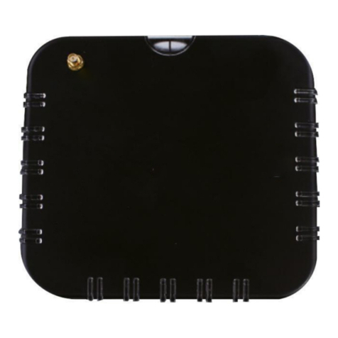
Firefly CUE User manual

MANUAL CONTROL UNIT
CUE
QUICK EXTINGUISHING SYSTEM
CUE

Contents
Introduction.........................................................................................................................1
Function...............................................................................................................................2
Installation...........................................................................................................................2
Electrical installation...........................................................................................................3
Mechanical installation........................................................................................................3
Start up ................................................................................................................................3
Led indicators......................................................................................................................4
Text messages......................................................................................................................5
*OPERATION STATUS MESSAGES ..........................................................................5
*MALFUNCTION MESSAGES....................................................................................5
*ACTIVITY MESSAGES ..............................................................................................9
Menus................................................................................................................................10
MENU SELECTION: SET DATE AND TIME ...........................................................11
MENU SELECTION: CHANGE SYSTEM STATE....................................................12
MENU SELECTION: SELECT LANGUAGE.............................................................13
Layout................................................................................................................................20
Technical data....................................................................................................................21

page 1
CONTROL UNIT CUE Rev. A MC Date: 030224
INTRODUCTION
The control unit CUE is the heart of the preventive protection system controlling and
operating all the different functions. The control unit receives and evaluates information
from each detector and activates appropriate output according to the programme, such
procedures as activation of relays, solenoid valves, explosive outputs and/or text messages.
The control unit CU-E has an integrated power supply as well as a battery back-up. Each
control unit may be installed close to the respective risk area that is being protected thus
minimizing installation and maintenance costs. The control unit is equipped for connection
to a network. Up to 31 units can be connected in a network controlled by one master unit
MUE.
The control unit CUE consists of six main components.
?Enclosure ?
?Front panel with LCD-?
window and keyboard
?Power supply card
?Transformer
?Main card
?Batteries ??
?
?
?

page 2
CONTROL UNIT CUE Rev. A MC Date: 030224
FUNCTION
1. Power Supply Unit with battery backup.
The control unit is supplied with AC-voltage from the mains which is transformed to
the required voltages for operating the different systems and for charging the battery.
If the main supply drops out, the control unit will automatically switch over to
battery back-up, thereby maintaining the full functionality of the central unit. When
the main switch is re-established, the control unit will automatically return to normal
AC operation, and the battery will be recharged.
2. Monitoring.
The control unit checks all the connected components with regard to electrical
operation and the internal function of hardware and software. In the case when a
fault alarm is activated the operator receives a message on the LCD-display
clarifying the type of fault.
3. Control system with pre-programmed functions..
For any detector indication or any other input signal, programmed procedures will
immediately take place. These procedures can vary depending on different factors
for example energy level, number of glows or sparks, indications from several
detectors or other input signals.
4. Electronic log-book
The control unit stores events and alarms in the electronic memory, which can be
recalled by the operator on demand.
INSTALLATION
The control unit is shipped ready for immediate installation complete with lockable
enclosure, mounting brackets and cable glands. This items are located under the "flap" in
the box (Note: The delivered mounting brackets and screws should be used). Choice of
cable entry will be determinated by the terminal connections to be used. The control unit
should be located in a well protected area. If the CU-E is located out-doors it must have
adequate weather protection.

page 3
CONTROL UNIT CUE Rev. A MC Date: 030224
ELECTRICAL INSTALLATION
1. Power supply
The main connection to the control unit should be individually fused.
2. Installation of cables
All cables to and from the control unit should be installed in the same way as signal
cables in general. The network cables should be installed at least 300 mm away from
the power cables or other source of main disturbance. The network cables must not
be spliced. If there is a risk for cable damage a mechanical protection shall be
provided.
3. Process earthing
It shall be preformed according to standard: XXXXXXXXx
MECHANICAL INSTALLATION
Follow the given instructions in the project documentation. The location of detectors and
extinguishing zones is essential for the correct function of the system.
FIREFLY AB CAN NOT HOLD RESPONSIBLE IF THE INSTALLATION IS NOT
PREFORMED ACCORDING TO THE DRAWINGS ISSUED BY FIREFLY AB.
START UP
Connect the control unit according to the instructions and connecting diagrams issued by
FIREFLY. When all connections have been completed,
turn on the switch SW1:
and SW3:
For switches location see the layout at the end of the manual.
Check if the system gives any malfunction alarms. Check out any reiterated alarms and
make corrections accordingly. Make a function test for all equipment connected and test
outgoing alarms from the control unit (process interlocking control).

page 4
CONTROL UNIT CUE Rev. A MC Date: 030224
LED INDICATORS
1. Mode indicator
Green LED ON –normal operation.
Green LED FLASHING –Control unit in test mode.
Green LED OFF –power failure.
2. Malfunction indicator
Red LED normally OFF.
Red LED FLASHING –Malfunction are registered.
Red LED goes out when malfunction have been corrected and a reset is made.
3. “Spare”
4. Glow indicator
Yellow LED normally OFF.
Yellow LED FLASHING momentary –glow indication.
5. Output indication
Yellow LED normally OFF.
Yellow LED ON an output is active.
6. Process stop indication
Red LED normally OFF.
Red LED FLASHING –system in process stop mode.
Red LED goes out when process stop has been deactivated and alarm has been reset.

page 5
CONTROL UNIT CUE Rev. A MC Date: 030224
TEXT MESSAGES
*OPERATION STATUS MESSAGES
Normal operating conditions –Green LED ON
Test mode where outputs for solenoid valves and explosive release are active.
(Note: All relays are deactivated. Malfunction alarm is given by the malfunction relay
while
the system is in this mode). This test mode is used when testing extinguishing functions.
Test mode where all outputs are deactivated. (Note: All relays are deactivated. Malfunction
alarm is given by the malfunction relay while the system is in this mode.) This test mode is
used when the system should not be in operation, i.e. during maintenance work or when the
process is taken out of operation. This test mode can also be used for testing the system.
*MALFUNCTION MESSAGES
Cause : Incoming supply voltage is missing.
Trouble-Shooting: Check incoming voltage. If supply voltage is correct
the fuses F1 and F2 in the control unit must be checked.
Action: Solve the problem in a suitable way. Replace the fuses.
Cause: Internal voltage is faulty
Trouble-Shooting: Check that no cables are disconnected or that something may
have caused a short-circuit.
Action: Solve the problem or contact Firefly AB.
STATE:
RUNNING
STATE:
NO RELAYS
STATE:
NO REL/OUTPUT
EXT. POWER ERROR
INT. POWER ERROR

page 6
CONTROL UNIT CUE Rev. A MC Date: 030224
Cause: Broken electrical circuit or faulty battery.
Trouble-Shooting Check that the battery cables are connected and that the batteries
are functioning.
Action: Connect the battery cables. Replace the faulty battery with a new
one.
Cause: Broken electrical circuit between control unit and solenoid
valve
Trouble-Shooting: Check that the cable connector on the solenoid valve is
correctly connected and that there is no damage on the
cable.
Action: Fasten the cable connector or change the cable.
Cause: No contact between control unit and detector No. 1
Trouble-Shooting: Check that the detector is connected in the control unit.
Check that the plug-in cable to the detector is connected to
the detector.
Check that the detector cable is correctly connected to the
control unit.
Check that no cable is damaged.
Action: Connect the detector.
Connect the cable
Correct connection.
Change to new cable.
Cause: Detector of incorrect type is connected to input D1.
Trouble-Shooting: Check in the project documentation which type of detector
should be connected.
Action: Install correct type of detector.
BAT. POWER ERROR
SOLENOID X ERROR
DETECTOR X NO RESP
DETECTOR X UNIT TYPE

page 7
CONTROL UNIT CUE Rev. A MC Date: 030224
Cause: Sensitivity of the detector connected to input D1 is not
Corresponding to the configuration in the control unit.
Trouble-Shooting: Check in the project documentation which sensitivity the
Detector should have.
Action: Change to correct sensitivity.
Cause: The temperature in the detector enclosure has exceeded the
preset temperature limit. The overheating can be caused by
to high temperature in the process or external factors, as
for example heat sources.
Trouble-Shooting: Find the cause for overheating.
Action: If the overheating is caused by the process, contact
FIREFLY for advice
Cause: Humidity in the detector enclosure.
Trouble-Shooting: If the detector is equipped with cooling air check the
instrument air quality.
Action: Dry the unit immediately. Use a cloth or similar for drying
the detector enclosure and the sensor cover. Blow the
electronics dry and clean by using instrument air.
Note: Do not dry the sensor wi
th hot air. The sensor
elements will be damaged if the temperature exceed 60?C.
Cause: The loop for explosive 1 faulty or not activated.
Trouble-Shooting: Check that the explosive output 1 is activated. See menu
EXPLOSIVE OUTPUTS. Check if the explosive loop is
faulty. (short circuits, broken circuits, and used or faulty
protractors.)
Action: Activate explosive output X by using menu EXPLOSIVE
OUTPUTS. Solve the problem in a suitable way.
DETECTOR X SENSITIV
DETECTOR X OVERTEMP
DETECTOR X HUMIDITY
EXPLOSIVE X ERROR

page 8
CONTROL UNIT CUE Rev. A MC Date: 030224
Cause: The circuit supervised by input sensor 1 is not in it's normal
position (normally open or closed).
Trouble-Shooting: Check the documentation for normal function of the circuit.
Also check all items connected to the input.
Action: Rectify the error.
Cause: Incorrect main program.
Trouble-Shooting: Contact FIREFLY AB.
Action: According to FIREFLY AB’s instructions.
(Flashing)
Cause: Incorrect master program or faulty processor.
Trouble-Shooting: Contact FIREFLY AB.
Action: According to FIREFLY AB’s instructions.
SENSOR X ERROR
UNKNOWN UNKNOWN
SYSTEM RESTART
CFG
-
GENTXT
CGF
-
DEDTXT
CGF
-
DETECT
CGF
-
SENSOR

page 9
CONTROL UNIT CUE Rev. A MC Date: 030224
Cause: Incorrect program file in the configuration program.
Trouble-Shooting: Contact FIREFLY AB.
Action: According to FIREFLY AB's instructions.
*ACTIVITY MESSAGES
Cause: Explosive output 1 has been activated.
Action: Reset the alarm with key for "reset".
Cause: The system has exceeded any of the presets criteria and
has therefore activated process stop.
Action: Find the cause for process stop and take necessary action.
Thereafter follow the routines that must be carried out after
process stop.
Cause:
Detector X has indicated a glowing particle. The energy
level was measured by the detector to be Y. The energy
level from a glowing particle is measured on a scale from
1-8, where 1 is the lowest and 8 is the highest energy.
Action: The message is for information only. The system has
carried out the pre-programmed procedures automatically.
EXPLOSIVE X ACTIVE
CGF
-
ENERGY
CGF
-
RISC
SYSTEM PR
-
STOP
DETECTOR X SPARK Y

page 10
CONTROL UNIT CUE Rev. A MC Date: 030224
MENUS
The control units has 6 keys to operate the unit.
Five are located under the display. This are as follows:
All functions keys are menu controlled.
The function for each key is displayed above respective key. The sixth key is used to reset
audible and visual alarms.
STANDARD MENUS
--DISPLAY EVENT LOG
-SET DATE AND TIME
-SELECT LANGUAGE
-CHANGE SYSTEM STATE
MENU SELECTION: DISPLAY EVENT LOG
Purpose: The log-book registers events reported by the control units.
It will log events sequentially as they happen i.e the last event will
be the first to be displayed.
1. The display will show the current status of the system.
Date Time
Control unit identity Rows for keys function
2. Press “MENU” to enter “MENU SELECTION”.
3. Step backwards or forwards by pressing “PREV.” or “NEXT” until the display
shows:
4. Press “ENTER”. The display shows now the latest message in the log-book.
030301 09:10:20 ???????????
KE
?
?
RR
?
?
/
?
?
KE94 V.
?
?
MENU
MENU SELECTION DISPLAY EVENT LOG
PREV NEXT
?
?
?
?
ABORT ENTER

page 11
CONTROL UNIT CUE Rev. A MC Date: 030224
5. Step backwards or forwards by pressing “PREV.” or “NEXT”.
6. To finish press “ABORT” and the display will return to show the current
information. If none of the keys has been pressed within 60 seconds, the display will
automatically return to show the current status of the system.
MENU SELECTION: SET DATE AND TIME
Purpose: To set date and time for the central unit which also updates all time
settings for the connected control units.
1. The display will show the current status of the system.
Date Time
Control unit identity Rows for keys function
2. Press “MENU” to enter “MENU SELECTION”.
3. Step backwards or forwards by pressing “PREV.” or “NEXT” until the display
shows:
4. Press “ENTER”. The display will show:
Current date and time Date and time to be set Cursor
5. The cursor will flash to show the digit to adjust. The cursor can be moved with the
key marked (>).
6. Set date and time with the keys “-1” and “+1” and press “ENTER”. The display will
return to show the current status of the system.
030301 09:10:20 ???????????
KE
?
?
RR
?
?
/
?
?
KE94 V.
?
?
MENU
MENU SELECTION SET DATE AND TIME
PREV NEXT
?
?
?
?
ABORT ENTER
030301 09:10:20 030301 09:10:
2
0
-
1 +1 > ABORT ENTER

page 12
CONTROL UNIT CUE Rev. A MC Date: 030224
MENU SELECTION: CHANGE SYSTEM STATE
Purpose: To change system state for the control unit.
1. The display will show the current status of the system.
Date Time
Control unit identity Rows for keys function
2. Press “MENU” to enter “MENU SELECTION”.
3. Step backwards or forwards by pressing “PREV.” or “NEXT” until the display
shows:
4. Press “ENTER”. The display will show:
Current system state System state to be selected
5. Step backwards or forwards among available systems states by pressing “PREV.” or
“NEXT
RUNNING -Normal operating condition –Green LED ON.
NO RELAYS -Test mode where outputs for solenoid valves and explosive
release are active. (Note: All relays are deactivated. Malfunction
alarm is given by the malfunction relay while the system is in this
mode.) This test mode is used when testing extinguishing
functions.
NO REL/OUTP -Test mode where all outputs are deactivated. (Note: All relays are
deactivated. Malfunction alarm is given by the malfunction relay
while the system is in this mode.) This test mode is used when the
system should not be in operation, i.e. during maintenance work
or when the process is taken out of operation. This test mode can
also be used for testing the system.
6. When the display shows the required system state press “ENTER” to select it.
The display will return to show the current status of the system.
030301 09:10:20 ???????????
KE
?
?
RR
?
?
/
?
?
KE94 V.
?
?
MENU
MENU SELECTION CHANGE SYSTEM STATE
PREV NEXT
?
?
?
?
ABORT ENTER
STATE: ??????????????????
PREV NEXT
?
?
?
?
ABORT ENTER

page 13
CONTROL UNIT CUE Rev. A MC Date: 030224
MENU SELECTION: SELECT LANGUAGE
Purpose: To select operating language for the central unit.
1. The display shows the current status of the system.
Date Time
Control unit identity Rows for keys function
2. Press “MENU” to enter “MENU SELECTION”.
3. Step backwards or forwards by pressing “PREV.” or “NEXT” until the display
shows:
4. Press “ENTER”. The display will show:
Present language Language to be selected
5. Step backwards and forwards among available languages by pressing ”PREV.” or
“NEXT”. When preferred language is shown on the display, press “ENTER” to
select it The display will return to show the current status of the system. All
information will be shown in the selected language.
030301 09:10:20 ???????????
KE
?
?
RR
?
?
/
?
?
KE94
V.
?
?
MENU
MENU SELECTION SELECT LANGUAGE
PREV NEXT
?
?
?
?
ABORT ENTER
LANGUAGE: ?????????????????
PREV
NEXT ABORT
ENTER

page 14
CONTROL UNIT CUE Rev. A MC Date: 030224
AVAILABLE MENUS DRIVEN BY EVENTS -DISPLAY ERROR LIST
The hidden menus will be available to -DISPLAY ERROR LIST
the operator when necessary due to system -RESET PROCESS STOP
configuration. The central unit will automatically -EXPLOSIVE OUTPUTS
activate the menus when needed. -RESET OUTPUTS
-FLOW SENSOR CALIBR.
MENU SELECTION: DISPLAY ERROR LIST
Purpose: To list existing errors. (Errors that have been remediated will
automatically be erased from the error list.)
1. The display shows the current status of the system.
Date Time
Control unit identity Rows for keys function
2. Press “MENU” to enter “MENU SELECTION”.
3. Step backwards or forwards by pressing “PREV.” or “NEXT” until the display
shows:
4. Press “ENTER”. The display will show:
*) For ex. SOLENOID 1
5. Step backwards and forwards among available system states by pressing ”PREV.”
or “NEXT”.
6. Press “ABORT” and the display will return to show the current status of the system.
030301 09:10:20 ???????????
KE
?
?
RR
?
?
/
?
?
KE94 V.
?
?
MENU
MENU SELECTION DISPLAY ERROR LIST
PREV NEXT
?
?
?
?
ABORT ENTER
ERROR ALARM IN: *) ???????????????
PREV
NEXT
?
?
?
?
ABORT
ENTER

page 15
CONTROL UNIT CUE Rev. A MC Date: 030224
MENU SELECTION: RESET PROCESS STOP
Purpose: To reset the system after a process stop.
1. The display shows the current status of the system.
Date Time
Control unit identity Rows for keys function
2. Press “MENU” to enter “MENU SELECTION”.
3. Step backwards or forwards by pressing “PREV.” or “NEXT” until the display
shows.
4. Press “ENTER”. The display will show:
Blocking time in seconds
The system can not be restarted before the countdown timer as reached 0000.
5. Press “ENTER” to deactivate the process stop.
Note: All necessary arrangements after a process stop must be finalised before
the process stop is deactivated.
The display shows:
6. Acknowledge the message by pressing “ACK.” X2. The display will automatically
return show the current status of the system..
030301 09:10:20 ???????????
KE
?
?
RR
?
?
/
?
?
KE94 V.
?
?
MENU
MENU SELECTION RESET PROCESS STOP
PREV NEXT
?
?
?
?
?
?
?
?
ENTER
PROCESS STOPED COUNTDOWN 0000
?
?
?
?
?
?
?
?
?
?
?
?
ABORT ENTER
KE ??????????SYSTEM PR-START
?
?
?
?
?
?
?
?
ACK.
?
?
?
?
?
?
?
?

page 16
CONTROL UNIT CUE Rev. A MC Date: 030224
MENU SELECTION: EXPLOSIVE OUTPUTS
Purpose: To switch the explosive outputs ON or OFF.
Note: When a explosive output has been activated it will automatically be switched off.
This means that the system can be left in a running position after an explosive output has
been activated. The protractor can be replaced without any influence on the other system
functions. The explosive outputs will be blocked for a preset time and can not be activated
before the countdown time is 0000.
1. The display shows the current status of the system.
Date Time
Control unit identity Rows for keys function
2. Press “MENU” to enter “MENU SELECTION”.
3. Step backwards or forwards by pressing “PREV.” or “NEXT” until the display
shows:
4. Press “ENTER”. The display will show:
Blocking time in seconds Blocking time in seconds
The explosive outputs can not be activated before the blocking time is 0000.
5. To activate explosive output 1 press “1-ON”. (To activate explosive output 2 press
“2-ON”).
030301 09:10:20 ???????????
KE
?
?
RR
?
?
/
?
?
KE94 V.
?
?
MENU
MENU SELECTION: EXPLOSIVE OUTPUTS
PREV
NEXT
?
?
?
?
?
?
?
?
ENTER
EXPL. 1 OFF 0000 EXPL . 2 OFF 0000
1
-
ON 2
-
ON
?
?
?
?
ABORT ENTER

page 17
CONTROL UNIT CUE Rev. A MC Date: 030224
6. The display shows:
Blocking time in seconds Blocking time in seconds
7. Press “ENTER”. The display will show.
The explosive 1 (2) is now activated.
Acknowledge the message by pressing “ACK.”. The display will automatically return to
show the current status of the system.
EXPL
. 1 ON 0000 EXPL . 2 ON 0000
1
-
OFF 2
-
OFF
?
?
?
?
ABORT ENTER
KE 01 030301 09:10:20 EXPLOSIVE 1 ON
?
?
?
?
?
?
?
?
ACK
?
?
?
?
?
?
?
?

page 18
CONTROL UNIT CUE Rev. A MC Date: 030224
MENU SELECTION: RESET OUTPUTS
Purpose: To manually reset outputs that have been programmed for manually
reset.
This menu can in some cases be delayed by the countdown time from the process stop.
1. The display shows the following:
NOTE: Check that the extinguishing process has been completed before
pressing YES.
2. Press “YES” and the outputs for manually reset will be reseted. The display will
automatically return to show the current status of the system..
RESET OUTPUTS
?
?
?
?
?
?
?
?
?
?
?
?
?
?
?
?
YES
Table of contents
Other Firefly Control Unit manuals