Fireye NEXUS NX04-1 User manual

1
®
DESCRIPTION
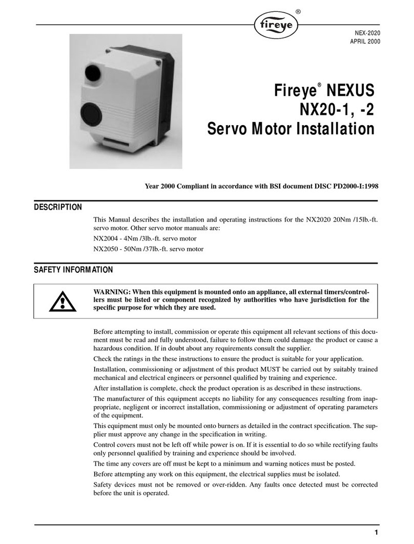
This manual describes the installation and operating instructions for the NX04 4Nm 3lb.-ft.
servo motor. Other servo motor manuals are:
NX2020 - 20Nm /15 lb.-ft. servo motor
NX2050 - 50Nm /37 lb.-ft. servo motor
SAFETY INFORMATION
WARNING:When this equipment is mounted onto an appliance, all external timers/control-
lers must be listed or component recognized by authorities who have jurisdiction for the
specific purpose for which they are used.
Before attempting to install, commission or operate this equipment all relevant sections of this docu-
ment must be read and fully understood, failure to follow them could damage the product or cause a
hazardous condition. If in doubt about any requirements consult the supplier.
Check the ratings in the these instructions to ensure the product is suitable for your application.
Installation, commissioning or adjustment of this product MUST be carried out by suitably trained
mechanical and electrical engineers or personnel qualified by training and experience.
After installation is complete, check the product operation is as described in these instructions.
The manufacturer of this equipment accepts no liability for any consequences resulting from inap-
propriate, negligent or incorrect installation, commissioning or adjustment of operating parameters
of the equipment.
This equipment must only be mounted onto burners as detailed in the contract specification. The sup-
plier must approve any change in the specification in writing.
Control covers must not be left off while power is on. If it is essential to do so while rectifying faults
only personnel qualified by training and experience should be involved.
The time any covers are off must be kept to a minimum and warning notices must be posted.
Before attempting any work on this equipment, the electrical supplies must be isolated.
Safety devices must not be removed or over-ridden. Any faults once detected must be corrected
before the unit is operated.
Year 2000 Compliant in accordance with BSI document DISC PD2000-I:1998
Fireye
®
NEXUS
NX04-1, -2
Servo Motor Installation
NEX-2004
APRIL 2000

2
Note:
The manufacturer of this equipment has a policy of continual product improvement and
reserves the right to change the specification of the equipment and the contents of this manual with-
out
These mounting and operating instructions are intended to give the knowledge which is necessary to
carry out the mounting and adjustment of NX04 servo motor safely and correctly.
Please read these instructions through carefully and pay particular attention to the advice and warn-
ings.
The NX04 servo motor has an output torque of 4Nm/3 lb.-ft. with an actuating time of 30 seconds for
90 degrees rotation. Two end travel limit microswitches with adjustment cams and a potentiometer
directly coupled to the output shaft are enclosed within its housing.
The output drive shaft can execute a rotation angle of 270 degrees maximum.
Two types of servo motors, 115 and 230 Volt AC, are available.
The field of use of this servo motor is predominantly for fuel valve and air damper actuation on
industrial burners.
SAFETY ADVICE
Device Safety
The servo motor must be used only for purposes corresponding to its construction and within the val-
ues specified in the technical data.
If current is applied simultaneously, to the terminals for open and close (Fig 3), uncontrollable move-
ment of the output drive shaft may occur, depending on the load on the shaft. This situation must be
prevented by the user by an electric interlock in the drive controller.
The installer should be satisfied that, as a result of the mounting, the commissioning or as a result of
the test adjustments on the actuator, no potential hazards will be produced for devices/machines/
plant.
Before mounting the servo motor, check the free movement of the valve/device.
After completing the mounting and adjustment, check the correct functioning of the servo motor.
Safety advice for mounting and adjustments
The Installer must be satisfied that, as a result of the commissioning or the test adjustments on the
servo motor, no potential hazards will be produced for personnel or the environment.
After completing adjustments check the correct functioning of the servo motor.
Check the functioning of the end position switches.
Check the correct functioning of any safety devices.
Carry out adjustments only in accordance with the instructions described in this documentation.
When adjustments are being carried out on an opened and switched-on servo motor there is the risk
that live parts can be touched.
Adjustments must therefore be carried out only by an electrician or a person having adequate train-
ing, who is aware of potential hazards.

3
®
SERVO MOTOR DESCRIPTION
FIGURE 1.
3
2
1. Plastic Cover
2. Mounting Holes
3. Locating Spigot
4. Output Shaft
5. Plug – PG9
6. Cable Entry
7. Limit Switch Cams x 2
8. Plastic Housing
9. Potentiometer
1
9
8
7
65
4

4
INSTALLATION
FIGURE 2. MECHANICAL MOUNTING
Fasten the NX04 servo motor using two bolts through a suitable mounting into the 5mm / 3/16 inch
holes (1) using spigot (2) for location so that the mounting surface (4) rests flat.
The output drive shaft (3) should be connected using a suitable arm, link or flexible coupling.
The mounting position of the NX04 servo motor is arbitrary.
Electrical installation
Loosen the two housing cover screws and pull the cover to remove it.
For the electrical installation of the NX04 servo motor, use the prescribed cable type (corresponding
to the environmental conditions).
Prepare the power supply, potentiometer, protective earth and control cables by suitably removing
sheaths and insulation.
Feed cables through screwed cable entry via suitable conduit and glands and place the stripped ends
of the leads into screw connection terminals and terminate as shown in the wiring in Figure 3.
Ensure that no bare wires protrude from the terminals and thus produce the risk of a current surge or
of a short circuit.
Store the cables such that they are not pinched when the housing cover is fitted or interfere with the
end travel switch cam mechanism or potentiometer coupling shaft.
In the case of a servo motor which is open and ready to operate there is the risk that live parts may be
touched and a shock received.
Switch on the power supply and check that the servo motor drives correctly.
Next carry out the adjustments/commissioning or otherwise replace the housing cover.
1
2
3
4

5
®
ADJUSTMENTS/COMMISIONING
Adjustments
Before the servo motor is opened or commissioned the Safety Information on Page 2 and safety
advice Section 2 must have been read.
The adjustment of the limit miscroswitches is carried out by turning the white adjusting discs to
rotate black cams. S1 and S2 (Figure 1)
Adjusting the end stops
In the case of a servo motor which has the cover removed and is ready to operate there is the risk that
live parts may be touched and thus a shock received.
Apply power to terminal 2 – the servo motor will move as far as the stop position switch given by
microswitch S1. If when adjusting stop positions, the servo motor runs up against a mechanical stop,
the motor will stall and make a humming noise.
When this happens the power supply for this direction of operation should be switched off.
To change the stop position, rotate cam S1 until it actuates the microswitch. at the correct position,
and the motor stops. The “direction 1” end stop is now adjusted.Apply power to terminal 3 – the
servo motor will move as far as the stop position given by microswitch S2.
To change the stop position, rotate cam S2 until it actuates the microswitch. at the correct position,
and the motor stops.
The open end stop is now adjusted.
FIGURE 3.
4
3
2
1
R1
S1
S2
5
6
7
Connections
1 = Neutral
2 = Direction 1
3 = Direction 2
4 = Not used
5 = + (S2)
6 = Wiper
7 = (S1)
Components
R1 = Potentiometer
S1 = Limit microswitch
S2 = Limit microswitch
F1, F2 = Potentiometer security screws

6
Housing Cover
Before mounting the housing cover onto the servo motor, check that the cams of the end stop
microswitches have been correctly adjusted and the connecting leads are correctly screwed tightly in
the terminals.
Check whether the actuating element is totally cent closed when the controller signals the cor-
responding end stop.
Ensure that the leads are not pinched between the housing and the housing cover and the circumfer-
ential rubber sealing ring in the housing is not damaged and is correctly seated in the groove.
Screw the housing cover tight using the two housing cover screws.
Commissioning
Before commissioning the servo motor the Safety Information on Page 2 and Safety advice in
Section 2 must have been read.
Switch on the power supply to the servo motor.
Drive the servo motor via the controller or by hand and check the correct functioning of the servo
motor, the microswitches and of the actuating element.
TECHNICAL DATA
Actuating time for 90° angle of rotation: 30 s
Nominal torque: 4 Nm / 3 lb.-ft.
Holding torque: 2.5 Nm / 1.8 lb.-ft.
Max. revolutions on the output drive shaft: 270°
Nominal voltage
Type NX04-1:
Type NX40-2: 120 V AC~± 10%, 50/60 Hz
230 V AC~± 10%, 50/60 Hz
Nominal power consumption: 5 VA
Angle of rotation limited by: 2 microswitches
Degree of protection: IP 31 NEMA 2
Installation position: Any
Working temperature range: 14°F - 140°F (- 10°C to + 60°C)
Duty cycle: 100%
Drive: 2-wire circuit
Potentiometer, single turn conductive plastic
Linearity
5kW
± 1%
Weight: 0.7 kg

7
®
FIGURE 4. DIMENSIONS NX04 SERVO MOTOR

8
FIGURE 5. WIRING DIAGRAM NX04 SERVO MOTOR
NOTICE
When Fireye products are combined with equipment manufactured by others and/or integrated into
systems designed or manufactured by others, the Fireye warranty, as stated in its General Terms and
Conditions of Sale, pertains only to the Fireye products and not to any other equipment or to the
combined system or its overall performance.
WARRANTIES
FIREYE guarantees for
one year from the date of installation or 18 months from date of manufacture
of its products to replace, or, at its option, to repair any product or part thereof (except lamps, elec-
tronic tubes and photocells) which is found defective in material or workmanship or which otherwise
fails to conform to the description of the product on the face of its sales order.
THE FOREGOING
IS IN LIEU OF ALL OTHER WARRANTIES AND FIREYE MAKES NO WARRANTY OF
MERCHANTABILITY OR ANY OTHER WARRANTY, EXPRESS OR IMPLIED.
Except as
specifically stated in these general terms and conditions of sale, remedies with respect to any product
or part number manufactured or sold by Fireye shall be limited exclusively to the right to replace-
ment or repair as above provided. In no event shall Fireye be liable for consequential or special dam-
ages of any nature that may arise in connection with such product or part.
TERMINAL 1
1 NEUTRAL
2 DIRECTION 1
L/N/C
3 DIRECTION 2
TERMINAL 2
15
26
37
POTENIOMETER
P1
M2
M3
M
AC
FIREYE NX-2004
3 Manchester Road APRIL 2000
Derry, New Hampshire 03038 USA
www.Fireye.com
This manual suits for next models
1
Table of contents
Other Fireye Servo Drive manuals
Popular Servo Drive manuals by other brands

Savch
Savch SDV3- E Series Quick manual

Pacific Scientific
Pacific Scientific OC950 EPROM installation instructions
Parker
Parker Gemini GV6 Series Quick reference guide
Siemens
Siemens SINAMICS S210 FSA Quick installation guide
Rockwell Automation
Rockwell Automation Allen-Bradley Kinetix 5300 user manual
Kollmorgen
Kollmorgen AKD user guide
