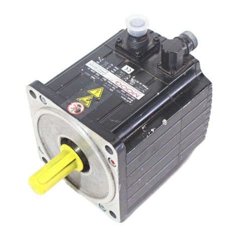
Moog D633-A Series User manual

DIRECT DRIVE SERVOVALVES SIZE 03 (NG6)
Original User Manual
(CA80942-001; Version 1.0, 12/08)
USER MANUAL
D633-A SERIES

© Moog GmbH User Manual "D633-A Series" (CA80942-001; Version 1.0, 12/08) A
Copyright
© 2008 Moog GmbH
Hanns-Klemm-Straße 28
71034 Böblingen
Germany
All rights reserved.
No part of this user manual may be reproduced in any form (print, photocopies, microfilm, or by any other
means) or edited, duplicated, or distributed with electronic systems without our prior written consent.
Offenders will be held liable for the payment of damages.
Subject to change without notice.
Telephone: +49 7031 622-0
Fax: +49 7031 622-191
E-mail: [email protected]
Internet: http://www.moog.com/Industrial

Table of Contents
© Moog GmbH User Manual "D633-A Series" (CA80942-001; Version 1.0, 12/08) i
Table of Contents
Copyright ................................................................................................................................................... A
List of Tables ..............................................................................................................................................v
List of Figures ............................................................................................................................................vi
1 General Information ..................................................................................1
1.1 Notes on the user manual........................................................................................................... 1
1.1.1 Validity and subject to change without notice................................................................. 1
1.1.2 Completeness ................................................................................................................ 1
1.1.3 Storage location ............................................................................................................. 1
1.1.4 Typographical conventions............................................................................................. 2
1.2 Supplementing documents ........................................................................................................ 2
1.3 Manufacturer’s declaration......................................................................................................... 3
1.4 Registered trademarks................................................................................................................ 3
1.5 Warranty and liability .................................................................................................................. 4
2 Safety .........................................................................................................5
2.1 Intended operation ...................................................................................................................... 5
2.2 Handling in accordance with safety requirements................................................................... 6
2.3 Responsibilities ........................................................................................................................... 7
2.4 Selection and qualification of personnel .................................................................................. 8
2.5 Structural modifications ............................................................................................................. 8
2.6 Occupational safety and health ................................................................................................. 9
2.7 General safety instructions ........................................................................................................ 9
2.8 Pressure limitation .................................................................................................................... 10
3 Product Description................................................................................11
3.1 Function and mode of operation.............................................................................................. 11
3.1.1 Representative depiction of the valve .......................................................................... 11
3.1.2 Permanent magnet linear force motor.......................................................................... 12
3.1.3 Signal interfaces........................................................................................................... 12
3.2 Safety function/fail-safe ............................................................................................................ 13
3.2.1 Mechanical fail-safe functions ...................................................................................... 13
3.2.1.1 Valves with fail-safe function F, D or M ................................................... 14
3.2.1.2 Mechanical fail-safe state........................................................................ 14
3.2.1.3 Fail-safe identification.............................................................................. 14
3.2.1.4 Bushing-spool identification..................................................................... 15
3.2.2 Restarting the valve...................................................................................................... 15
3.3 Hydraulics .................................................................................................................................. 16
3.3.1 Open-loop flow control (Q-control) ............................................................................... 16
3.3.2 Valve configurations and hydraulic symbols ................................................................ 16
3.3.2.1 4-way and 3-way operation ..................................................................... 16
3.3.2.2 2-way and 2x2-way operation ................................................................. 17
3.3.3 Leakage port Y............................................................................................................. 17
3.3.3.1 Y-identification......................................................................................... 17
3.4 Activation ................................................................................................................................... 18

Table of Contents
© Moog GmbH User Manual "D633-A Series" (CA80942-001; Version 1.0, 12/08) ii
3.5 Nameplate .................................................................................................................................. 18
3.5.1 Model number .............................................................................................................. 18
3.5.2 Type Designation ......................................................................................................... 19
3.5.2.1 Valve version identification...................................................................... 19
3.5.2.2 Rated flow identification .......................................................................... 20
3.5.2.3 Maximum pressure identification............................................................. 20
3.5.2.4 Bushing-spool identification..................................................................... 21
3.5.2.5 Linear force motor identification .............................................................. 21
3.5.2.6 Fail-safe identification.............................................................................. 22
3.5.2.7 Y-identification......................................................................................... 22
3.5.2.8 Sealing material identification.................................................................. 22
3.5.2.9 Valve connector identification.................................................................. 23
3.5.2.10 Command signal identification ................................................................ 23
3.5.3 Data matrix code .......................................................................................................... 23
4 Technical Data .........................................................................................25
4.1 General technical data .............................................................................................................. 25
4.2 Hydraulic data............................................................................................................................ 26
4.3 Static and dynamic data ........................................................................................................... 26
4.4 Electrical data ............................................................................................................................ 27
4.5 Emissions................................................................................................................................... 27
5 Characteristic Curves .............................................................................29
5.1 Dependency of flow and pressure drop .................................................................................. 29
5.2 Flow signal characteristic curve .............................................................................................. 29
5.3 Spool stroke signal characteristic curve ................................................................................ 30
5.4 Pressure signal characteristic curve....................................................................................... 30
5.5 Step response and frequency response ................................................................................. 31
6 Transportation and Storage ...................................................................33
6.1 Unpacking/checking a delivery ................................................................................................ 34
6.2 Scope of delivery of the valve .................................................................................................. 34
6.3 Storage ....................................................................................................................................... 34
7 Mounting and Connection to the Hydraulic System............................35
7.1 Dimensions (installation drawings) ......................................................................................... 36
7.2 Mounting surface....................................................................................................................... 37
7.2.1 Surface quality.............................................................................................................. 37
7.2.2 Mounting pattern of mounting surface.......................................................................... 37
7.3 Mounting the valves .................................................................................................................. 38
7.3.1 Tools and materials required........................................................................................ 38
7.3.2 Specification for installation screws.............................................................................. 38
7.3.3 Procedure..................................................................................................................... 39
8 Electrical Connection .............................................................................41
8.1 Wiring ......................................................................................................................................... 42
8.1.1 Tools and materials required........................................................................................ 42
8.1.2 Electrical connection of the valves ............................................................................... 42
8.2 Valve connector X1 ................................................................................................................... 43
8.2.1 M12 valve connector X1............................................................................................... 43
8.2.2 MIL valve connector X1................................................................................................ 43
8.3 Grounding screw ....................................................................................................................... 44

Table of Contents
© Moog GmbH User Manual "D633-A Series" (CA80942-001; Version 1.0, 12/08) iii
9 Start-up.....................................................................................................45
9.1 Preparations............................................................................................................................... 47
9.2 Start-up of the valves ................................................................................................................ 47
9.3 Filling and flushing the hydraulic system............................................................................... 48
9.4 Start-up of the hydraulic system.............................................................................................. 49
9.4.1 Venting the hydraulic system ....................................................................................... 49
10 Operation .................................................................................................51
10.1 Preparations for operation ....................................................................................................... 52
10.2 Operation of the valve............................................................................................................... 53
10.3 Shutting down the valve ........................................................................................................... 53
11 Service .....................................................................................................55
11.1 Removing the valves................................................................................................................. 57
11.1.1 Tools and materials required........................................................................................ 57
11.1.2 Procedure..................................................................................................................... 57
11.2 Maintenance............................................................................................................................... 58
11.2.1 Checking and replacing the port O-rings...................................................................... 58
11.2.1.1 Tools and materials required................................................................... 58
11.2.1.2 Checking and replacing the O-rings ........................................................ 58
11.3 Troubleshooting ........................................................................................................................ 59
11.3.1 Leaks............................................................................................................................ 59
11.3.1.1 Leak at the valve connecting surface ...................................................... 59
11.3.1.2 Leak at the linear force motor screw plug ............................................... 59
11.3.2 No hydraulic response by the valve ............................................................................. 60
11.3.3 Instability of the external control loop ........................................................................... 60
11.4 Repair ......................................................................................................................................... 61
11.4.1 Contact persons for repairs.......................................................................................... 61
12 Disposal ...................................................................................................63
13 Accessories and Spare Parts.................................................................65
13.1 Accessories ............................................................................................................................... 65
13.2 Spare parts................................................................................................................................. 66
14 Index.........................................................................................................67
15 Appendix..................................................................................................75
15.1 Abbreviations, symbols and identification letters ................................................................. 75
15.2 Additional literature................................................................................................................... 77
15.2.1 Moog publications ........................................................................................................ 77
15.3 Quoted standards...................................................................................................................... 77
15.3.1 DIN ............................................................................................................................... 77
15.3.2 DIN EN ......................................................................................................................... 77
15.3.3 DIN EN ISO..................................................................................................................78
15.3.4 EN ................................................................................................................................ 78
15.3.5 IEC ............................................................................................................................... 78
15.3.6 ISO ............................................................................................................................... 78
15.3.7 MIL ............................................................................................................................... 78
15.4 Quoted directives ...................................................................................................................... 78

Table of Contents
© Moog GmbH User Manual "D633-A Series" (CA80942-001; Version 1.0, 12/08) iv
For your notes.

List of Tables
© Moog GmbH User Manual "D633-A Series" (CA80942-001; Version 1.0, 12/08) v
List of Tables
Table 1: Position of the spool in the mechanical valve fail-safe state .......................................................... 14
Table 2: Fail-safe identification in the type designation ............................................................................... 14
Table 3: Bushing-spool identification in the type designation ...................................................................... 15
Table 4: Y-identification in the type designation........................................................................................... 17
Table 5: Valve version identification in the type designation........................................................................ 19
Table 6: Rated flow identification in the type designation ............................................................................ 20
Table 7: Maximum pressure identification in the type designation............................................................... 20
Table 8: Bushing-spool identification in the type designation ...................................................................... 21
Table 9: Linear force motor identification in the type designation ................................................................21
Table 10: Fail-safe identification in the type designation ............................................................................... 22
Table 11: Y-identification in the type designation........................................................................................... 22
Table 12: Sealing material identification in the type designation ................................................................... 22
Table 13: Valve version identification in the type designation........................................................................ 23
Table 14: Command signal identification in the type designation .................................................................. 23
Table 15: General technical data ................................................................................................................... 25
Table 16: Hydraulic data ................................................................................................................................ 26
Table 17: Static and dynamic data................................................................................................................. 26
Table 18: Electrical data................................................................................................................................. 27
Table 19: Specification for installation screws ............................................................................................... 38
Table 20: Accessories.................................................................................................................................... 65
Table 21: Spare parts..................................................................................................................................... 66
Table 22: Abbreviations, symbols and identification letters ........................................................................... 75

List of Figures
© Moog GmbH User Manual "D633-A Series" (CA80942-001; Version 1.0, 12/08) vi
List of Figures
Figure 1: Representative depiction of a direct drive servovalve...................................................................11
Figure 2: Representative depiction of a permanent magnet linear force motor ........................................... 12
Figure 3: 4-way operation with mechanical fail-safe function F (hydraulic symbol) ..................................... 16
Figure 4: 3-way operation with mechanical fail-safe function F (hydraulic symbol) ..................................... 16
Figure 5: 2-way operation with mechanical fail-safe function M (hydraulic symbol)..................................... 17
Figure 6: 2x2-way operation with mechanical fail-safe function M (hydraulic symbol)................................. 17
Figure 7: Nameplate (example).................................................................................................................... 18
Figure 8: Flow signal characteristic curve .................................................................................................... 29
Figure 9: Setup for measuring the flow signal characteristic curve .............................................................. 29
Figure 10: Spool stroke signal characteristic curve........................................................................................ 30
Figure 11: Pressure signal characteristic curve of the valves with zero lap ................................................... 30
Figure 12: Setup for measuring the pressure signal characteristic curve ...................................................... 30
Figure 13: Step response of the spool stroke................................................................................................. 31
Figure 14: Frequency response of the spool stroke ....................................................................................... 31
Figure 15: Installation drawings for valves with M12 or MIL valve connector, dimensions in mm (inches).... 36
Figure 16: Mounting pattern of mounting surface as per ISO 4401-03-03-0-05, dimensions in mm (inches) 37
Figure 17: M12 valve connector X1 (circuit and pin assignment)................................................................... 43
Figure 18: MIL valve connector X1 (circuit and pin assignment).................................................................... 43
Figure 19: Grounding screw........................................................................................................................... 44
Figure 20: Repair quality seal......................................................................................................................... 61

1 General Information Notes on the user manual
© Moog GmbH User Manual "D633-A Series" (CA80942-001; Version 1.0, 12/08) 1
1 General Information
1.1 Notes on the user manual
Notes on the user manualThis user manual applies only to the standard models of D633-A series valves.
It contains the most important information for ensuring proper and correct oper-
ation of the valves.
ÖChapter "2.1 Intended operation", page 5
ÖChapter "2.2 Handling in accordance with safety requirements", page 6
The contents of this user manual and the product-related hardware and soft-
ware documentation relevant to the particular application must be read, under-
stood and followed in all points by each person responsible for machine plan-
ning, assembly and operation before work with and on the valves is started.
This requirement applies in particular to the safety instructions.
ÖChapter "1.1.2 Completeness", page 1
ÖChapter "2.3 Responsibilities", page 7
ÖChapter "2.4 Selection and qualification of personnel", page 8
ÖChapter "2.2 Handling in accordance with safety requirements", page 6
This user manual has been prepared with great care in compliance with the rel-
evant regulations, state-of-the-art technology and our many years of knowl-
edge and experience. The full contents have been generated to the best of the
authors’ knowledge.
However, the possibility of error remains and improvements are possible.
Please feel free to submit any comments about possible errors and incomplete
information to us.
1.1.1 Validity and subject to change without notice
Validity of the user manual
and subject to change
without notice
The information contained in this user manual is valid and correct at the mo-
ment of release of this version of the user manual. The version number and re-
lease date of this user manual are indicated in the footer.
Changes may be made to this user manual at any time and without reasons
being given.
1.1.2 Completeness
Completeness of the
user manual
This user manual is only complete in conjunction with the product-related hard-
ware and software documentation required for the relevant application.
Available documents:
ÖChapter "1.2 Supplementing documents", page 2
1.1.3 Storage location
Storage location for the
user manual
This user manual together with all of the product-related hardware and soft-
ware documentation relevant to the particular application must be kept ready to
hand and accessible close to the valve or the higher-level machine at all times.
Special models of the valves custom-made for specific customers are not
explained in this user manual.
Please contact us or one of our authorized service centers for information
on these special models.

1 General Information Supplementing documents
© Moog GmbH User Manual "D633-A Series" (CA80942-001; Version 1.0, 12/08) 2
1.1.4 Typographical conventions
Typographical
conventions
1.2 Supplementing documents
Supplementing
documents
The following supplementing documents are available:
• Application notes "Technical Note TN 353"
Protective grounding and electrical shielding of hydraulic valves with
integrated electronics
• Application notes "Technical Note TN 494"
Maximum permissible lengths of electric cables for the connection of
hydraulic valves with integrated electronics
DANGER Identifies safety instructions which are intended to warn
of immediately imminent danger to life and limb or serious
damage to property.
Failure to comply with these safety instructions will inevi-
tably result in fatalities, serious personal injuries (disable-
ment) or serious damage to property!
WARNING Identifies safety instructions which are intended to warn
of possible danger to life and limb or possible serious
damage to property.
Failure to comply with these safety instructions may result in
fatalities, serious personal injuries (disablement) or serious
damage to property!
CAUTION Identifies safety instructions which are intended to warn of mi-
nor personal injuries or minor damage to property.
Failure to comply with these safety instructions may result in
minor personal injuries or minor damage to property.
Identifies important notes/information
• or – Identifies listings
ÖIdentifies references to another chapter, another page, table or
illustration in the user manual
"…" Identifies headings of chapters or titles of documents, which
are referenced
Blue text Identifies hyperlinks in the PDF file
1., 2., … Identifies steps in a procedure which must be performed in
consecutive order
tIdentifies the direction of the valve opening (e.g., PtT)
The supplementing documents mentioned here are not included in the
valves’ scope of delivery. They are available as accessories.
ÖChapter "13.1 Accessories", page 65
The PDF files of the supplementing documents can be downloaded from
the following link:
http://www.moog.com/Industrial/Literature

1 General Information Manufacturer’s declaration
© Moog GmbH User Manual "D633-A Series" (CA80942-001; Version 1.0, 12/08) 3
1.3 Manufacturer’s declaration
Manufacturer’s
declaration
The valves comply with the standards specified in the associated manufac-
turer’s declaration.
The valves comply with the requirements of the Machine Directive 98/37/EC.
Refer to the associated manufacturer’s declaration for the applied standards.
1.4 Registered trademarks
Registered trademarksMoog and Moog Authentic Repair®are registered trademarks of Moog Inc. and
its subsidiaries.
Microsoft®and Windows®are either registered trademarks or trademarks of
the Microsoft®Corporation in the USA and/or other countries.
Please contact us or one of our authorized service centers for the manu-
facturer’s declaration.
All of the product and company names mentioned in this user manual are
possibly registered names or trademarks of the respective manufacturers.
The use of these names by third parties for their own purposes may in-
fringe the rights of the manufacturers.
The absence of the symbols ® or ™ does not indicate that the name is
free from trademark protection.

1 General Information Warranty and liability
© Moog GmbH User Manual "D633-A Series" (CA80942-001; Version 1.0, 12/08) 4
1.5 Warranty and liability
Our General Terms and Conditions of Sale and Payment always apply. These
are made available to the buyer at the latest on conclusion of the contract.
Exclusion of warranty and
liability
Among other things, warranty and liability claims for personal injury and dam-
age to property are excluded if they are caused by one or more of the following:
• Work with and on the valves or handling of the valves by non-qualified
personnel
ÖChapter "2.4 Selection and qualification of personnel", page 8
• Non-intended operation
ÖChapter "2.1 Intended operation", page 5
• Handling not in accordance with safety requirements
ÖChapter "2.2 Handling in accordance with safety requirements", page 6
• Omission of the occupational safety and health measures required for the
particular application
ÖChapter "2.6 Occupational safety and health", page 9
• Failure to observe this user manual or the product-related hardware and
software documentation relevant to the particular application
• Failure to observe the safety standards of the manufacturer and the oper-
ator of the machine relevant to the particular application
• Failure to observe the latest versions of the relevant national and interna-
tional regulations, standards and guidelines (such as e.g., the EU Machin-
ery Directive, the regulations of the trade association and of TÜV or VDE)
in the configuration, construction and operation of the machine with all of
its installed components
• Omission of suitable safety devices for limiting the pressure at the hydrau-
lic ports
ÖChapter "2.8 Pressure limitation", page 10
• Failure to comply with the preconditions for satisfying the EMC protection
requirements
• Use of the valves in a state that is not technically faultless or not opera-
tionally safe
• Unauthorized or improperly performed structural modifications, repairs or
maintenance
ÖChapter "2.5 Structural modifications", page 8
ÖChapter "11 Service", page 55
• Failure to adhere to the inspection and maintenance instructions of the
manufacturer and the operator of machine
• Failure to adhere to all of the technical data relating to the storage, trans-
portation, mounting, removal, connection, start-up, configuration, opera-
tion, cleaning, maintenance or elimination of any faults, in particular the
ambient conditions and the data pertaining to the hydraulic fluid used
ÖChapter "4 Technical Data", page 25
• Improper storage, transportation, mounting, removal, connection, start-up,
configuration, operation, cleaning, maintenance, elimination of any faults
or disposal
• Use of unsuitable or defective accessories or of unsuitable or defective
spare parts
ÖChapter "13 Accessories and Spare Parts", page 65
• Catastrophes caused by foreign objects or force majeure

2 Safety Intended operation
© Moog GmbH User Manual "D633-A Series" (CA80942-001; Version 1.0, 12/08) 5
2Safety
2.1 Intended operation
Intended operation
The valves may only be operated as a component part of a higher-level overall
system, for example in a machine.
They may be used only as control elements to control flow and/or pressure in
hydraulic circuits that regulate position, speed, pressure and power.
The valves are intended for use with mineral-oil-based hydraulic oils. Use with
other media requires our prior approval.
Correct, reliable and safe operation of the valves requires qualified project
planning as well as proper utilization, transportation, storage, mounting, re-
moval, electrical and hydraulic connection, start-up, configuration, operation,
cleaning and maintenance.
The valves may only be started up when the following is ensured:
• The higher-level machine with all of its installed components complies
with the latest versions of the relevant national and international regula-
tions, standards and guidelines (such as e.g., the EU Machinery Directive,
the regulations of the trade association and of TÜV or VDE).
• The valves and all of the other installed components are in a technically
fault-free and operationally reliable state.
• No signals which can lead to uncontrolled movements in the machine are
transmitted to the valves.
Intended operation also includes the following:
• Observation of this user manual
• Handling of the valves in accordance with safety requirements
ÖChapter "2.2 Handling in accordance with safety requirements", page 6
• Adherence to all of the inspection and maintenance instructions of the
manufacturer and the operator of the machine
• Observation of all product-related hardware and software documentation
relevant to the particular application
• Observation of all safety standards of the manufacturer and the operator
of the machine relevant to the particular application
• Observation of all the latest versions of the national and international reg-
ulations, standards and guidelines relevant to the particular application
(such as e.g., the EU Machinery Directive, the regulations of the trade as-
sociation and of TÜV or VDE)
WARNING The valves may be operated exclusively within the frame-
work of the data and applications specified in the user
manual.
Any other or more extensive use is not permitted.
WARNING Use of the valves in potentially explosive environments is
not permitted.

2 Safety Handling in accordance with safety requirements
© Moog GmbH User Manual "D633-A Series" (CA80942-001; Version 1.0, 12/08) 6
Handling in accordance
with safety requirements
In order to ensure that the valves are handled in accordance with safety re-
quirements and operated without faults, it is essential to observe the following:
• All of the safety instructions in the user manual
• All of the safety instructions in the product-related hardware and software
documentation relevant to the particular application
• All of the safety instructions in the safety standards of the manufacturer
and the operator of the machine relevant to the particular application
• All of the relevant national and international safety and accident preven-
tion regulations, standards and guidelines, such as e.g., the safety regula-
tions of the trade association, of TÜV or VDE, in particular the following
standards pertaining to the safety of machinery:
–DIN EN ISO 12100
–DIN EN 982
–DIN EN 563
–EN 60204
Observing the safety instructions and the safety and accident prevention regu-
lations, standards and guidelines will help to prevent accidents, malfunctions
and damage to property!
2.2 Handling in accordance with safety requirements
WARNING It is the responsibility of the manufacturer and the opera-
tor of the machine to ensure that the valves are handled in
accordance with safety requirements.
WARNING As in any electronic control system, the failure of certain
components in valves as well might lead to an uncon-
trolled and/or unpredictable operational sequence. All
types of failure on a system level must be taken into con-
sideration and appropriate protective measures must be
taken.
The use of automatic control technology in a machine calls for
special measures.
If automatic control technology is to be used, the user should,
in addition to all of the potentially available standards or guide-
lines on safety-engineering installations, consult the manufac-
turers of the components used in great depth.

2 Safety Responsibilities
© Moog GmbH User Manual "D633-A Series" (CA80942-001; Version 1.0, 12/08) 7
2.3 Responsibilities
Responsibility of the
manufacturer and the
operator of the machine
The manufacturer and the operator of the machine are responsible for ensuring
that work with and on the valves and handling of the valves is planned and per-
formed in accordance with the directions given in this user manual and in the
product-related hardware and software documentation relevant to the particu-
lar application.
The manufacturer and the operator of the machine are in particular responsible
for ensuring the following:
• Selection and training of personnel
ÖChapter "2.4 Selection and qualification of personnel", page 8
• Intended operation
ÖChapter "2.1 Intended operation", page 5
• Handling in accordance with safety requirements
ÖChapter "2.2 Handling in accordance with safety requirements", page 6
• Taking and monitoring of the occupational safety and health measures re-
quired for the particular application
ÖChapter "2.6 Occupational safety and health", page 9
• Observation of all of the safety standards of the manufacturer and the op-
erator of the machine relevant to the particular application
• Observation of the latest versions of the relevant national and interna-
tional regulations, standards and guidelines (such as e.g., the EU Machin-
ery Directive, the regulations of the trade association and of TÜV or VDE)
in the configuration, construction and operation of the machine with all of
its installed components
• Installation of suitable safety devices for limiting the pressure at the hy-
draulic ports
ÖChapter "2.8 Pressure limitation", page 10
• Compliance with the preconditions for satisfying the EMC protection re-
quirements
• Use of the valves in a technically faultless and operationally safe state
• Prevention of unauthorized or improperly performed structural modifica-
tions, repairs or maintenance
ÖChapter "2.5 Structural modifications", page 8
ÖChapter "11 Service", page 55
• Definition and observation of the application-specific inspection and main-
tenance instructions
• Adherence to all of the technical data relating to the storage, transporta-
tion, mounting, removal, connection, start-up, configuration, operation,
cleaning, maintenance or elimination of any faults, in particular the ambi-
ent conditions and the data pertaining to the hydraulic fluid used
ÖChapter "4 Technical Data", page 25
• Proper storage, transportation, mounting, removal, connection, start-up,
configuration, operation, cleaning, maintenance, elimination of any faults
or disposal
• Use of suitable and faultless accessories and of suitable and faultless
spare parts
ÖChapter "13 Accessories and Spare Parts", page 65
• Handy and accessible storage of this user manual and of the product-re-
lated hardware and software documentation relevant to the particular ap-
plication
ÖChapter "1.1.3 Storage location", page 1

2 Safety Selection and qualification of personnel
© Moog GmbH User Manual "D633-A Series" (CA80942-001; Version 1.0, 12/08) 8
2.4 Selection and qualification of personnel
Selection and qualification
of personnel
Qualified users
Qualified users are specialized personnel with the required knowledge and ex-
perience who have been trained to carry out such work. The specialized per-
sonnel must be able to recognize and avert the dangers which they are ex-
posed to when working with and on the valves.
In particular, these specialized personnel must be authorized to operate,
earth/ground and mark hydraulic and electrical devices, systems and power
circuits in accordance with the standards of safety engineering. Project plan-
ners must be fully conversant with automation safety concepts.
Warranty and liability claims for personal injury or damage to property are
among others excluded if such injury or damage is caused when the valves are
worked on or handled by non-qualified personnel.
ÖChapter "1.5 Warranty and liability", page 4
2.5 Structural modifications
Structural modifications
Warranty and liability claims for personal injury and damage to property are
among others excluded if they are caused by unauthorized or improperly per-
formed structural modifications or other interventions.
ÖChapter "1.5 Warranty and liability", page 4
WARNING Only properly qualified and authorized users may work
with and on the valves.
WARNING In the interests of avoiding damage to the valves or acces-
sories, structural modifications, on account of the com-
plexity of the internal components of the valves or acces-
sories, may only be carried out by us or one of our autho-
rized service centers.

2 Safety Occupational safety and health
© Moog GmbH User Manual "D633-A Series" (CA80942-001; Version 1.0, 12/08) 9
2.6 Occupational safety and health
Occupational safety and
health measures and
equipment
2.7 General safety instructions
General safety
instructions
WARNING The magnets in the permanent magnet linear force motor
create strong magnetic fields, which can have a disruptive
effect on sensitive devices, such as e.g., cardiac pace-
makers. The relevant safe distances appropriate for the
device must be observed.
CAUTION Depending on the application, significant levels of noise may
be generated when the valves are operated.
If necessary, the manufacturer and operator of the machine
must take appropriate sound insulation measures or stipulate
that suitable safety equipment, such as e.g., ear protection, be
worn.
CAUTION Falling objects, such as e.g., valve, tool or accessory, can
cause injury.
Suitable safety equipment, such as e.g., safety shoes, must be
worn to provide protection against injury.
CAUTION Valves and hydraulic port lines can become very hot during op-
eration.
Suitable safety equipment, such as e.g., work gloves, must be
worn to provide protection against injury before touching the
valve or the connection cables during such operations as
mounting, removal, electrical and hydraulic connection, trou-
bleshooting or servicing.
CAUTION When handling hydraulic fluids, observe the safety provisions
applicable to the hydraulic fluid used.
If necessary, suitable safety equipment, such as e.g., work
gloves, must be worn.
WARNING Only properly qualified and authorized users may work
with and on the valves.
ÖChapter "2.4 Selection and qualification of personnel",
page 8
WARNING Observe and adhere to the technical data and in particular
the information given on the valve nameplate.
ÖChapter "4 Technical Data", page 25
CAUTION This user manual and the product-related hardware and soft-
ware documentation relevant to the particular application must
be inserted in the machine’s operating instructions.

2 Safety Pressure limitation
© Moog GmbH User Manual "D633-A Series" (CA80942-001; Version 1.0, 12/08) 10
2.8 Pressure limitation
Safety devices for
pressure limitation
WARNING Excessive pressure at the hydraulic ports damages the
valve and can cause unsafe states in the machine and per-
sonal injury.
Pressure-limiting valves, for example, or other comparable
safety devices must be installed to limit the pressure at all of
the hydraulic ports to the specified maximum operating pres-
sure.
Maximum operating pressure:
ÖChapter "4 Technical Data", page 25

3 Product Description Function and mode of operation
© Moog GmbH User Manual "D633-A Series" (CA80942-001; Version 1.0, 12/08) 11
3 Product Description
3.1 Function and mode of operation
Function of the valves:
throttle valves
The valves of the D633-A series are direct drive servovalves (DDV: Direct
Drive Valve). The valves are throttle valves for 2-, 3-, 4- or even 2x2-way appli-
cations.
They are suitable for electrohydraulic position, speed, pressure and force con-
trol even for high dynamic requirements. They control flow.
3.1.1 Representative depiction of the valve
Representative depiction
of the valve
Figure 1: Representative depiction of a direct drive servovalve
Item Designation Further information
1 Grounding screw ÖChapter "8.3 Grounding screw", page 44
2 Valve connector X1 ÖChapter "8.2 Valve connector X1", page 43
3 Spool
4 Bushing
5 Permanent magnet linear
force motor
ÖChapter "3.1.2 Permanent magnet linear force motor",
page 12
T…Y Ports ÖChapter "7.2.2 Mounting pattern of mounting surface",
page 37

3 Product Description Function and mode of operation
© Moog GmbH User Manual "D633-A Series" (CA80942-001; Version 1.0, 12/08) 12
3.1.2 Permanent magnet linear force motor
Representative depiction
of a permanent magnet
linear force motor
Figure 2: Representative depiction of a permanent magnet linear force motor
Permanent magnet linear
force motor
A permanent magnet linear force motor (figure 2 or item 10 in figure 1) is used
to drive the valve spool (item 8 in figure 1).
In contrast to proportional-solenoid drives, the permanent magnet linear force
motor can move the spool from the spring-centered center position in both
working directions. This results in high actuating power for the spool simulta-
neously with very good static and dynamic properties.
The permanent magnet linear force motor is a differential motor excited by per-
manent magnets. Some of the magnetic force is already provided by the per-
manent magnets. The linear force motor’s power demand is thus significantly
lower than is the case with comparable proportional solenoids.
The linear force motor (figure 2 or item 10 in figure 1) drives the valve spool
(item 8 in figure 1). The spool starting position is determined in the de-ener-
gized state by the centering springs (item 5 in figure 2). The linear force motor
enables the spool to be displaced from the starting position in both directions.
Here, the actuating power of the linear force motor is proportional to the coil
current.
The high forces of the linear force motor and centering springs effect precise
spool movement even against flow and frictional forces.
3.1.3 Signal interfaces
The valves are provided with a valve connector X1 for the command signal.
Pin assignment of valve connector X1:
ÖChapter "8.2 Valve connector X1", page 43
Item Designation
1Coil
2 Bearing
3Armature
4 Permanent magnets
5 Centering springs
6 Screw plug
Table of contents
Other Moog Servo Drive manuals
Popular Servo Drive manuals by other brands

Festo
Festo CMMT-AS-C2-3A Series Assembly and installation
Quanser
Quanser SRV02 Ball and Beam user manual
SEW-Eurodrive
SEW-Eurodrive CMP Series Addendum to the operating instructions
TQ
TQ ILM-E Assembly instructions

Rockwell Automation
Rockwell Automation Allen-Bradley Ultra3000 Migration guide
Inovance
Inovance IS300S002-C user manual
