First Degree Fitness E820A User manual

USER GUIDE
E820A

2

3
Introduction
WARNING
Do not remove hands while crank is in motion. The crank will continue to rotate and could
cause injury.
Congratulations on your purchase of E820A.
FIRST DEGREE FITNESS is proud to present the Rower as a FULL COMMERCIAL USE
product featuring patented Adjustable Fluid Resistance.
As with any piece of fitness equipment, consult a physician before beginning your E820A
exercise program.
Follow all instructions carefully for correct assembly, Tank filling, water treatment,
service and safety.
Access to our world-wide distributor and service network is available at
www.firstdegreefitness.com
Check contents of Box 1 and Box 2 to ensure all parts are present and correct prior to
assembly.
Training with the E820A

4
Contents
Safety ................................................................................... 5
Assembly ............................................................................... 7
E820A Box 1 & Box 2 Contents................................................ 8
Assembly Instructions ............................................................. 9
Operation Instructions 13
Bluetooth Auto-Adjust Monitor............................................... 16
Calibration Procedure ........................................................... 17
Maintenance & Troubleshooting 18
Tank Belt Adjustment 20
International Warranty........................................................... 21

5
Safety
Safety Information
•Before using this product, it is essential to read this ENTIRE operation manual and
ALL instructions. The Rower is intended for use solely in the manner described in this
manual.
•UNDERSTANDING EACH AND EVERY WARNING TO THE FULLEST IS IMPORTANT
•As with any piece of fitness equipment, consult a physician before beginning your
Rower exercise program.
•Please be aware that any fitness regiment, before being undertaken, is best preceded
by a physical checkup from a certified physician.
•Injuries to health may result from incorrect or excessive training.
• WARNING Heart rate monitoring systems may be inaccurate. Over exercise may
result in serious injury or death. If you feel faint, stop exercising immediately.
•Do not allow children unattended access to the machine.
•Please keep hands away from moving parts, as indicated by the warning label on the
Main Frame of your machine.
•If any of the adjustment devices are left projecting, they could interfere with the
user’s movement.
•Do not store in freezing conditions with water in the Tank as it can expand and crack
the components.
Installation
•Place on a stable, flat surface in a horizontal position during use for maximum
stability.
•Check regularly and follow all instructions for maintenance as specified in this manual.
•Replace immediately any defective parts and do not operate unit until all repairs are
complete.

6
Safety
Proper Usage
• Do not use any equipment in any way other than designed or intended by the
manufacturer. It is imperative that FIRST DEGREE FITNESS equipment is used
properly to avoid injury.
• Injuries may result if exercising improperly or excessively. It is recommended that all
individuals consult a physician prior to commencing an exercise program. If at any time
during exercise you feel faint, dizzy or experience pain, STOP EXERCISING and consult
your physician.
• Keep body parts (hands, feet, hair, etc.), clothing and jewelry away from moving parts
to avoid injury.
• Follow instructions provided in this manual for correct foot position and basic rowing
techniques.
• For more detailed rowing techniques, please refer to our International website
www.firstdegreefitness.com
Inspection
• DO NOT use or permit use of any equipment that is damaged and/or has worn or broken
parts. For all FIRST DEGREE FITNESS equipment use only replacement parts supplied by
FIRST DEGREE FITNESS.
• EQUIPMENT MAINTENANCE - Preventative maintenance is the key to smooth operating
equipment as well as to keep your liability to a minimum. Equipment needs to be
inspected at regular intervals.
• Ensure that any person(s) making adjustments or performing maintenance or repair of
any kind is qualified to do so.
• DO NOT ATTEMPT TO USE OR REPAIR ANY ACCESSORY APPROVED FOR USE WITH THE
FIRST DEGREE FITNESS EQUIPMENT WHICH APPEARS TO BE DAMAGED OR WORN.
• Check regularly and follow all instructions for maintenance as specified in this manual.
• Replace immediately any defective parts and do not operate unit until all repairs are
complete.
Operating Warnings
• Keep children away from the equipment. Parents or others supervising children must
provide close supervision of children if the equipment is used in the presence of children.
• Do not allow users to wear loose fitting clothing or jewelry while using equipment. It is
also recommended to have users secure long hair back and up to avoid contact with
moving parts.
• All bystanders must stay clear of all users, moving parts and attached accessories and
components while machine is in operation.
• WARNING Do not insert fingers into Tank!

7
Assembly
Live area and Training area
Product Specifications
Product Class: SC
Braking System: Speed Independent
Product Net Weight: 84.6kg (186.12lb)
Product Gross Weight: 107kg (235.4lb)
Maximum Safe Operating Surface Area: 276cm (108.66”) Length x 222cm (87.40”) Width
Dimensions: 1560mm (61.42”) Length x 1020mm (40.16”) Width x 1400mm (55.12”) Height
Maximum User Weight: 150kg (330lb)
Footprint:2160mm x 1620mm or upright 1400mm x 1020mm
Product Highlights
Seat Frame
Main frame
Telescoping tube / gas assisted shock
Complete Platform
Control Arm
10 x fluid Force
-massive range
Of resistance at
The turn of a lever
Auto-level, Bluetooth
monitor - real time
power in watts per
repetition

8
E820A Box 1 & 2 Contents
Item Qty.Description Item Qty. Description
1 1 Main Frame with Telescoping Tube
and Internal Gas Assist Shock 7 9 Foot Levelers
2 1 Baseplate 8 1 Multi-tool
3 1 Seat Frame 9 1 Touch up paint
4 1 Seat Back 10 2 D Cell Duracell Battery
5 1 Lower Seat 11 1 Funnel and Hose
6 1 Right pedal 12 1 Owners Manual
Hardware KIT
13 1 Handle Bar & Dome Nut 19 8 M6 Washer
14 8 M6x20mm Bolt 20 3 M10 Washer
15 4 M8x15mm Bolt 21 4 M8 Springs Washer
16 8 M8x45mm Bolt 22 1 4mm Allen Key
17 3 M10x20mm Bolt 23 1 6mm Allen Key
18 2 M10 Nyloc Nut 24 4 Water Treatment Tablets
9
Assembly Instructions
8
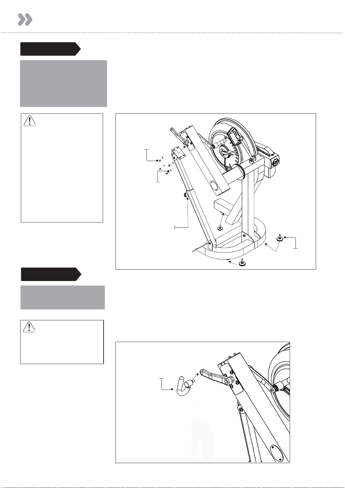
STEP 1 Main Frame Assembly Instructions
a) Attach Telescoping Tube to the underside of the
control arm using 4xM8x15mm Bolts[15] and 4x M8
Spring Washers[21].
b) Thread the 3xFoot levelers[7] into underside of base.
Adjust as required.
2
1
12
REQUIRED
4 x M8 x 15mm Blots [15]
4 x M8 Spring Washers [21]
3 x Foot Levelers[7]
1
REQUIRED
Right Pedal [6]
STEP 2
a) Secure Right Pedal [6] onto Crank arm. The pedal threads
have a blue coating which will feel very tight when threaded
onto the crank arm. This is a type of thread locker, and
once in contact with the crank arm threads will activate in
approximately 15minutes.
CAUTION
The control arm is heavy
and may swing freely during
this stage of assembly.
The Adjuster Knob is
pre-tightened from the
factory in the optimal
position for assembly in
relation to the control arm.
Do not loosen the Adjuster
knob until the Telescoping
Tube has been safely
secured to the underside
M8 Spring Washers
Adjuster Knob
Foot Leveler
M8x15mm Bolts
2
CAUTION
Extreme over-tightening
could damage the aluminum
threads on the crank arm.
Note: Allow 15 minutes for the thread
locker to activate before first time use.
Check pedal tightness periodically
thereafter with a 15mm wrench.
Right Pedal
Crank Arm Assembly Instructions

10
Assembly Instructions
b) Mount the Left Channel over the top of the footplate
dome Bolts and then slide forward. Once Channel is
properly positioned, attach to T-Track using
4x M8x45 mm Bolts[16]. Repeat this procedure to
install Right Footplate and Channel.
STEP 3 Installing the Baseplate
a) Tilt the T-Channel slightly to allow the footplate (with
pre-installed Bolts) to slide underneath as shown.
8
2
1
12
REQUIRED
T-Track
Channel Right
Channel Left
2 x Footplate
8 x M8x45mm Blots [16]
Foot Leveler [7]
Footplate T-Track
2
1
Left
Channel
Slide Channel
forward
1
Channel Slot
2
3
8x45mmBolts
4
c) Stand Baseplate upright to install 6x Foot Leveler[7]
as shown. Once foot levelers are installed, the
completed Baseplate can be installed onto the Main
Frame of the E820.
Footplate
Channel Left
Footplate
Channel Right
T-Track
1
Completed Baseplate
1
2
11
Assembly Instructions
STEP 4 Installing Baseplate to the Main Frame
2
1
REQUIRED
3 x M10x20mm [17]
2 x M10 Nylock Nut [18]
3 x M10 Washer [20]
a) Mount the baseplate onto the Main Frame using
mounting pins as a locator
Then, secure with 3x M10x20mm Bolt[17], 2x M10
Nylock Nut[18] and 3x M10 Washer[20].
Note : Center M10 Bolt does not require Nut.
1
2
3
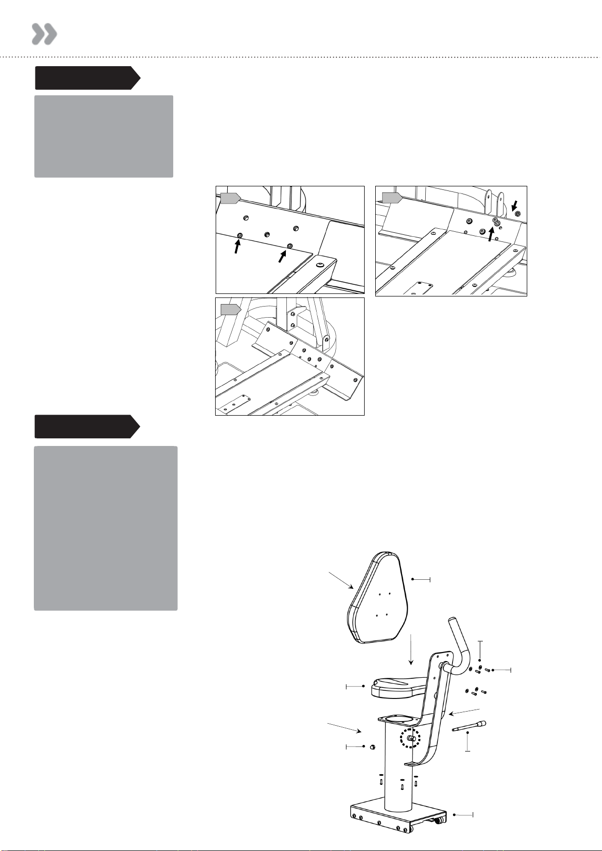
STEP 5 Seat Assembly and Installing Seat to the Main Frame
1
REQUIRED
Seat Frame [3]
Seat Back [4]
Lower Seat [5]
4 x M6x20mm Bolts [14]
4 x M6 Washer [19]
Handle Bar [13]
Dome Nut [13]
a) Thread the Handle Bar [13] through the Shaft
b) Tighten the Handle Bar [13] with the Dome Nut[13]
c) Install Seat Back[4] with 4x M6x20 Bolts[14] and M6
Washer[19].
d) Install Lower Seat[5] with 4x M6x20 Bolts[14] and M6
Washer[19].
b)
a)
c)
d)
Seat Frame
Handle Bar
M6 x 20 Bolt
M6 Washer
M10 Dome Nut
Lower Seat
Seat Back

12
Assembly Instructions
STEP 6 Installing Seat to the Main Frame
a) Seat Stop: Must be lowered to allow seat onto
Baseplate track. Must ALWAYS be in the LOCKED
position when seat is occupied on Baseplate. Must be
lowered to allow seat removal. To LOCK, raise and
locate. To UNLOCK, lift and drop rearward.
CAUTION
The Seat Stop Must be in
the locked position whenever
the seat is in use..
WARNING
Do not under any
circumstances attempt to
remove / install seat while
occupied.
b) Seat Installation: Tilt the seat slightly upward to allow
the front rollers to engage the channel. Then, lift the
rear level and, while engaging the Seat Lock Release
Lever, slide the seat onto the Baseplate as shown.
Usage: The seat has four positions. To move forward
or rearward, depress the Seat Lock Release Lever
and move freely to whichever position you require.
c) To remove the seat: Lift and lower the Rear Safety lock,
depress the Seat Lock Release Lever and slide the seat
rearward.

13
Operation Instructions
Chain Tensioning Bolts: Allows for tightening the Chain or adjustment from side to
side. Make sure when tightening only to adjust the same amount for both Bolts,
otherwise the sprocket will be misaligned.
Note: Tightening the right Bolt only will pull the right side of the crank assembly
toward you, tightening the left will pull the left side toward you. Use this feature to
realign the rear with the front sprocket if needed or when changing to a new chain.
E820 Control Arm
Crank arm Bolts: Loosen
all 8 Bolts slightly before
adjusting/tightening the
Chain. Inspection plate: Open to
check chain tension.
Warning: Do not check
chain tension by hand!
Adjuster Knob: Loosen to al-
low the Control Arm to travel
through 90 degrees of travel.
Note the Telescoping Tube is
gas assisted.
Tighten securely when desired
workout position is reached.

14
CAUTION
Use a drop cloth under
the Tank when filling to
avoid damaging to floor or
carpet.
Do not fill past the
calibration mark as
indicated on the Tank
level sticker or water
spillage may occur.
Tank Filling and Water Treatment
Operation Instructions
REQUIRED
Funnel and Hose[11]
a) Filling requires a large bucket (not supplied) and the
supplied water Funnel and Hose[11]. Filling will take
approximately 8 liters of water.
b) Open the yellow fill plug on the back of Tank and insert
hose (rotating the impeller slightly may be necessary
to allow the hose to pass). In areas where tap water
quality is known to be poor, FD F recommends the use
of distilled water.
c) Move the Tank adjuster handle to level 10 and begin
filling. Do not fill the Tank higher than the level
indicator on the front of the clear shell.
d) Once filling is complete follow the water treatment
schedule below.
INITIAL WATER TREATMENT
Add One Water Treatment Tablet per full Tank. Do NOT, UNDER ANY CIRCUMSTANCE,
USE A WATER TREATMENT TABLET OTHER THAN THOSE SUPPLIED WITH YOUR UNIT.
Your unit purchase includes 4xWater Treatment Tablets, which is sufficient for several
years of use.
To purchase additional Water Treatment Tablets, please consult your nearest regional
dealer/distributor or check our website at www.firstdegreefitness.com
WARNING
Impeller blades are sharp!
Do not Place fingers in
Tank to adjust impeller
position.
It is recommended to use
the end of the hose should
the impeller require
adjustment
CAUTION
In areas where tap water
quality is known to be
poor, FDF recommends
the use of distilled water.
NOTE: For simple, fast and efficient filling and/or drainage of the Fluid Tank, we have a
battery operated pump (rechargeable via USB) available as an option. We recommend
this to any commercial facility, with multiple units, that has a need to drain and refill
Tanks from time to time. To purchase, contact your nearest First Degree Fitness
distributor or go to our website on www.firstdegreefitness.com for details.
Note: The Lower Black Tank Plug is Permanently Sealed.
Orange Tank Plug
Water Funnel
and Hose
supplied with
unit

15
Operation Instructions
CHANGING RESISTANCE LEVEL
Changing resistance on your Unit is simple. The level
of resistance is determined by the level indicator lo-
cated on the front of the Tank. Level one indicates
lightest resistance, level ten represents heaviest
resistance. The Tank’s variable fluid resistance
technology ensures an instant catch and constant
resistance throughout the movement.
Your Unit computer will automatically adjust to the
resistance level selected on the Tank. Allow three to
four seconds after adjusting resistance handle for
the correct resistance level to be achieved.
LONG-TERM WATER TREATMENT
WARNING: DO NOT USE ANY OTHER WATER TREATMENT TABLET OTHER THAN THOSE SUPPLIED WITH
YOUR UNIT.
The amount of time between water treatments can vary greatly depending on your
unit’s location and exposure to sunlight. Typically you can expect to treat your Tank
water every 12-24 months. If water becomes discolored or shows signs of algae /
bacterial growth simply add one Water Treatment Tablet.
16
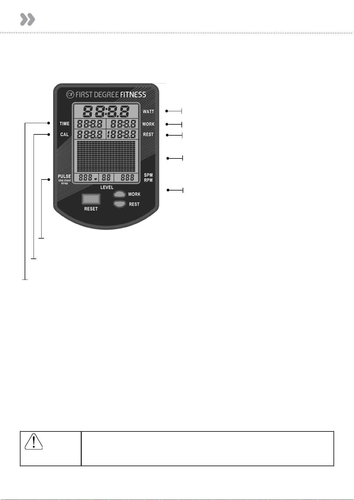
Bluetooth Auto-Adjust Monitor
Auto Start: Commence exercise to activate.
Reset all values: Press and hold RESET button for 3 seconds.
Auto Power Down: Over 5 minutes. All values revert to zero after restart.
WARNING:
Heart rate monitoring systems may be inaccurate, Over exercising
may result in serious injury or death. If you feel faint stop exercising
immediately and seek professional medical advice.
NOTE: Heart Rate Transmitter Chest Strap is sold separately.
WATT: Measures peak power in watts, calculating the strength and acceleration provided to accurately
measure a user’s power.
TRAINING DATA: Data gathered from each workout is displayed in a power curve and cumulative power
graph, enabling real-time comparisons for effective progressive training.
AUTO ADJUST LEVEL: Built in potentiometer automatically adjusts the computer’s resistance level
according to the position of the Fluid Force Lever on the Tank .
BLUETOOTH CONNECTIVITY: Each Unit is fitted with the most advanced console technology, enabling
Bluetooth connectivity with any compatible smart device. Designed to integrate with rowing and
fitness apps, the console will assist with effective training progression, capturing and comparing data
for the competitive individual. (Including FDF Power Zone APP available via FDF Website)
PULSE: Compatible with Polar Heart Rate Receiver and Transmitter Chest Strap.
WATT: Power measured in watts
WORK: Duration of exercise segment
POWER GRAPH: Press RESET to change display
from Power Curve to Cumulative Power Graph
LEVEL: Auto-level adjust to Fluid Force lever
CAL: Calories burned per hour at the current Watts. Shows total calories burned when exercise is
stopped.
REST: Duration of rest period
TIME: Auto start elapsed time.

17
Calibration Procedure
Press and hold 「RESET」and「REST」for 5 seconds.
Display will show “ - - - - “
Turn handle to Level 1.
Press Reset.
Display will now show Level 2.
Level 1 Calibration is complete.
Turn handle to Level 2.
Press Reset.
Display will now show Level 3.
Level 2 Calibration is complete.
Repeat for 3,4,5,6,7,8,9,10. Level 10
Press Reset.
Repeat the steps back to level 1.
Calibration is complete.

18
Maintenance & Troubleshooting
For further information, manuals and warranty requests visit
www.firstdegreefitness.com/support
Problem Solution
Water changer color or becomes cloudy. Change Unit location to reduce direct exposure to sunlight.
Add water treatment or change Tank water as directed in
the water treatment section of this manual. Consider
using distilled water to refill Tank.
I want to drain the fluid Tank on my
E820A.
It is recommended to take your unit outdoors, open the
Orange fill plug, and lay unit on its back to facilitate draining
process.
For simple, fast and efficient filling and/or drainage of the
Fluid Tank, we have a battery operated pump (rechargeable
via USB) available as an option. We recommend this to any
commercial facility, with multiple units, that has a need to
drain and refill Tanks from time to time. To purchase,
contact your nearest First Degree Fitness distributor or go
to our website on www.firstdegreefitness.com for details.
The computer display is erratic and
illuminates, but does not register with
movement.
It is possible that there is a loose connection. Check that the
computer lead is connected properly to the unit. If connected
properly check Sensor gap. Contact your local dealer if this fails
to address the problem.
The computer does not illuminate after
battery installation.
Replace/reinstall batteries in correct position and try again.
If the LCD screen fails to illuminate, try rotating the batter-
ies slightly in the computer.
If this fails, contact your local service center.
The Bluetooth Auto-Adjust Monitor LEVEL
is not synchronized with the Tank LEVEL.
Bluetooth Auto-Adjust Monitor LEVEL needs to be
recalibrated. Please refer to "Calibration Procedure"
page 17 of this manual.
Knocking noise from inside the control arm
while training, especially when changing
directions
Chain requires tightening or adjustment.
Open inspection plate located on front of control arm and
check tension using a screwdriver or other tool. Use the
chain tensioning Bolts located at the rear of the control
arm to tighten or adjust as needed. The chain should have
approx. 3mm of slack when properly adjusted. See P.13 for
details.
Pedal is loose (either left or right) and
cannot be retightened.
Aluminum crank arm threads are stripped.
Contact service center for replacement. Then check weekly
as recommended.
Pedals slip during hard training.
PK Tank belt requires tightening.
Remove large inspection plate next to the Tank, insert a
long tool to push the rear end cap out from the inside,
exposing the Tank belt tensioning Bolt. Loosen Tank Bolts
slightly. Remove upper rubber belt cover to expose the PK
belt. Tighten the Tank tensioning Bolt until the belt is too
tight to be twisted from side to side more than 45 degrees
by hand.

19
Maintenance & Troubleshooting
To ensure maximum lifespan and optimal performance follow these steps:
1. Keep your E820A in a dry, clean climate controlled environment at room
temperature.
2. Only treat water with FDF genuine Water Treatment Tablets. Refer to ‘water
treatment’ section on page 14.
3. Periodically clean your machine with disinfectant, applied using a lint free cloth.
4. Wipe dust off the machine.
5. For information on how to service your machine visit
firstdegreefitness.com/support
Item Time Frame Instructions
Seat and Frame. Weekly. Wipe down weekly with lint free cloth or more often with
heavy club use.
PK Belt Tension. Monthly. Check monthly for signs of slippage. Adjust/tighten as
required.
Tank and Water
Treatment. 12 months to 2 years. Follow instructions as specified in the “Water Treat-
ment” section of this manual.
Chain Drive.
Check every 100 hours for
correct
tension.
Open the inspection plate and check tension using a
screwdriver or other tool. Tighten as required using
chain tensioning Bolts located at the end of the control
arm.
Handle Assembly.
Check weekly using Multi-
Tool (supplied) to ensure
Handle Assembly is
securely tightened into
Crank Arm.
The handle should be checked on a regular basis.
Continued use of a loose Handgrip can cause
damage to the Crank Arm threads, necessitating
replacement.
20
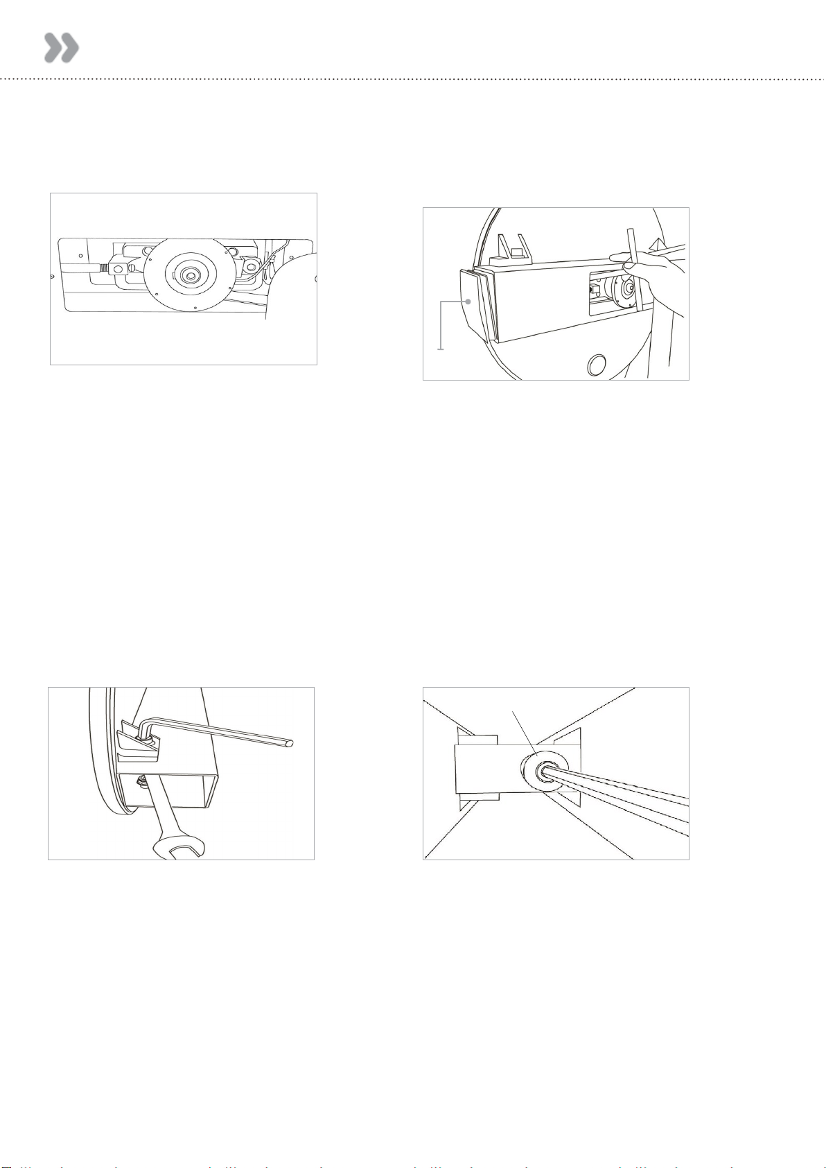
Tank Belt Adjustment
1. Remove large metal inspection plate. 2. Using a long tool, push out the rear
end cap as pictured below left. This
will give you access to the Tank
tensioning Bolt (shown lower right).
3. Loosen both the rear and front Tank
Bolts slightly as shown. Remove
front Rubber Belt Cover.
4. Using a 6mm Allen Key, tighten the
Belt using the Tank Tensioning Bolt
until the belt no longer slips during
hard rowing.
End Cap
Note: Do not over tighten Tank Bolts.
Tip: Twist the Belt by hand to gauge
tightness. Correct tension should be
obtained when no longer able to twist
more than 45 degrees
Tank Tensioning Bolt
Table of contents
Other First Degree Fitness Elliptical Trainer manuals

Popular Elliptical Trainer manuals by other brands


Gazelle
Gazelle GAZELLE POWER PLUS owner's manual

York Fitness
York Fitness Active 120 owner's manual

Xterra
Xterra EU150 owner's manual

Horizon Fitness
Horizon Fitness Endurance 4 owner's manual

NordicTrack
NordicTrack Cxt 1100 Elliptical Manuale d'istruzioni

NordicTrack
NordicTrack Audiostrider Cx650 Elliptical Gebruiksaanwijzing