First Degree Fitness fluid e820 Fitness UBE User manual
Owners Manual
2
Contents
1. Contents of E820 Box.
2. E820 assembly instructions.
3. E820 Control arm.
4. Tank filling and water treatment.
5. Long term water treatment and basic operation.
6. The E820 Ergometer with USB Function.
7. Maintenance/Troubleshooting.
8. Tank belt drive adjustment.
Training with the E820
As with any piece of fitness equipment, consult a physician before begin-
ning your E820 exercise program.
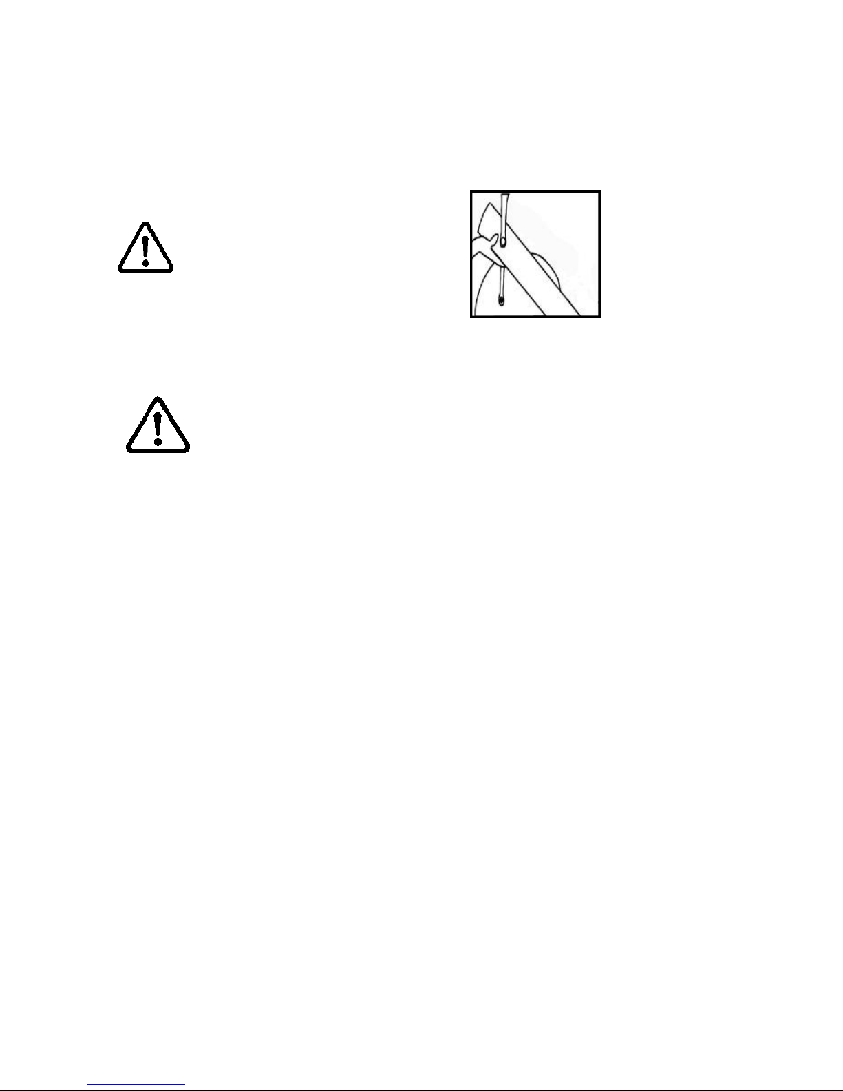
CAUTION
Use two hands and follow all safety instructions whenever raising or low-
ering the E820 control arm.
Warning
Do not remove hands while crank is in motion. The crank will continue to
rotate and could cause injury.
3
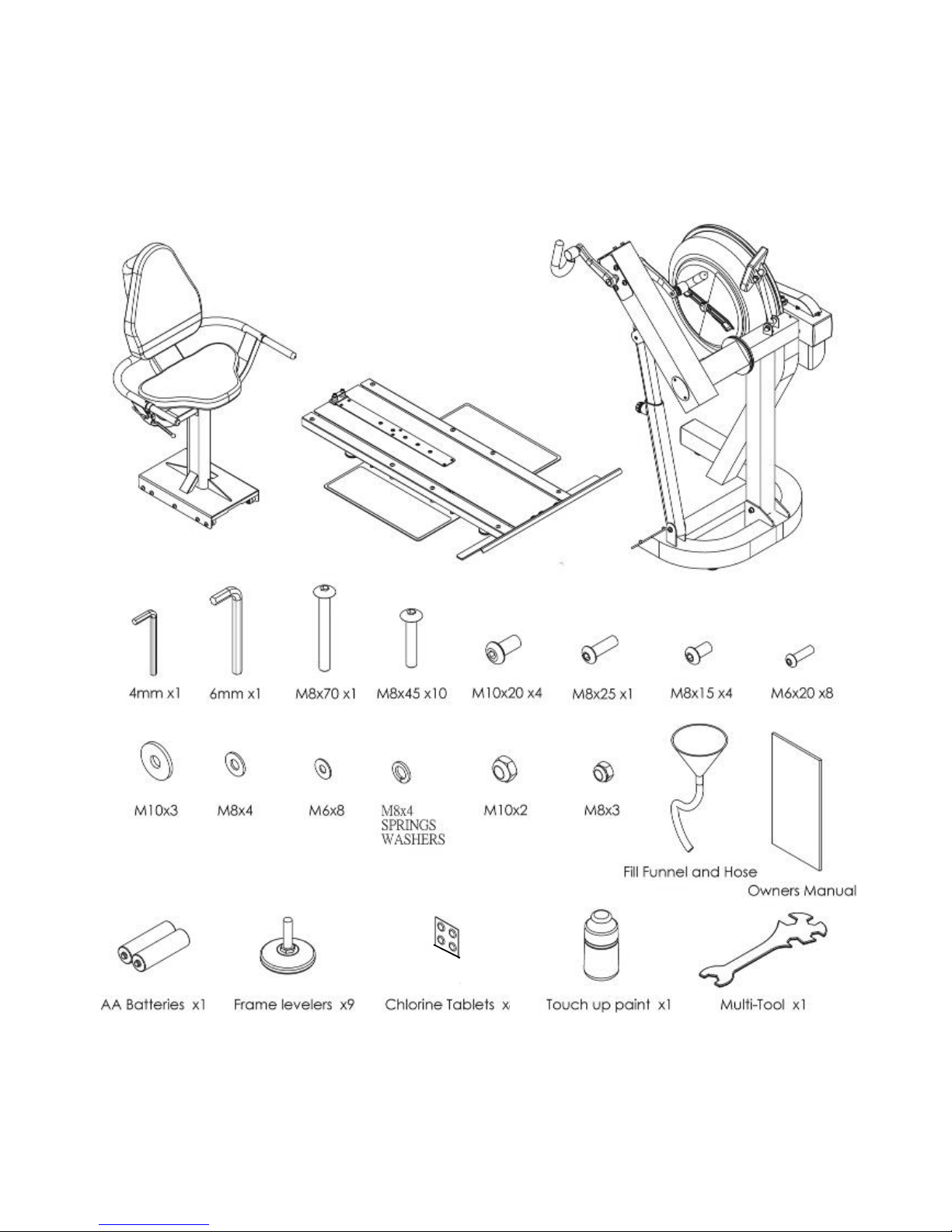
4
1x Main Frame with Telescoping Tube and
Internal Gas Assist Shock
1x Seat and Base
E820 Box Contents

4
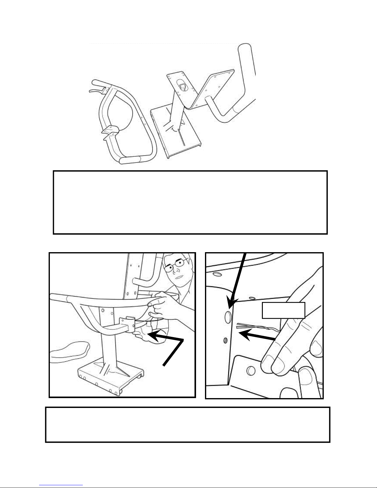
Step 1: Remove contents from box. Attach telescoping tube to the underside of the
control arm using 4x M8x15mm bolts and 4x M8 spring washers.
The control arm is heavy and may swing freely during this stage
of assembly. The Adjuster knob is pre-tightened from the factory in the optimal posi-
tion for assembly in relation to the control arm. Do not loosen the Adjuster knob until
the telescoping tube has been safely secured to the underside of the control arm.
CAUTION
E820 Assembly Instructions
4x 8x15mm bolts
and 4x M8 spring
washers
Adjuster knob

5
Step 4: Secure right pedal onto Crank arm. The pedal threads have a blue
coating which will feel very tight when threaded onto the crank arm. This is
a type of thread locker, and once in contact with the crank arm threads will
activate in approximately 15minutes.
Caution! Extreme over-tightening could damage the aluminum threads on
the crank arm.
Note: Allow 15 minutes for the thread
locker to activate before first time use.
Check pedal tightness periodically
thereafter with a 15mm wrench.
E820 Assembly Instructions

6
E820 Baseplate Assembly
Contents:
1x T-Track 2x Footplate
1x Channel Right 1x Bolt Pack (for both baseplate/seat)
1x Channel Left
T-Track
Footplate
Channel
Left
Foot-
Channel
Right
Bolt pack

7
Install the Footplates/Channels:
Step One: Tilt the T-Channel slightly to allow the footplate (with pre-installed bolts)
to slide underneath as shown.
Step Two: Mount the Left Channel over the top of the footplate dome bolts and
then slide forward. Once Channel is properly positioned , attach to T-Track using
4x M8x45mm Bolts.
Repeat this procedure to install Right Footplate and Channel.
Footplate
T-Track
Left Channel
4x 8x45mm
bolts
Slide Channel
forward
Channel Slot

8
Step One: Stand Baseplate upright to install 4x Foot levelers as shown.
Once foot levelers are installed, the completed baseplate can be
installed onto the mainframe of the E820.
Install Baseplate to Mainframe
Step Two: Mount the baseplate on-
to the Mainframe using mounting
pins as a locator
Then, secure with 3x M10x25mm
Bolt, 2x M10 Nylock Nut and 3x
M10 Washer
Note center M10 Bolt does not re-
quire Nut.
Foot leveler
Completed
Baseplate
Baseplate to Mainframe.
3x M10x25mm Bolts, 3x M10 Washer
and 2x M10 Nylock Nuts.
Mounting pins on
E820 Mainframe

9
Install Seat onto Baseplate
Seat Stop: Must be lowered to al-
low seat onto Baseplate track.
Must ALWAYS be in the LOCKED
position when seat is occupied on
Baseplate.
Must be lowered to allow seat re-
moval.
To LOCK, raise and locate. To
UNLOCK, lift and drop rearward.
Seat Installation: Tilt the seat slightly upward to allow the front rollers to en-
gage the channel. Then, lift the rear level and, while engaging the Seat Lock Re-
lease Lever, slide the seat onto the Baseplate as shown.
Usage: The seat has four positions. To move forward or rearward, depress the
Seat Lock
Release Lever and move freely to whichever position you require.
CAUTION: The Seat Stop Must be in the LOCKED position whenever the
seat is in use.
To remove the seat: Lift and lower the Rear Safety lock, depress the Seat Lock
Release Lever and slide the seat rearward.
WARNING: Do not under any circumstances attempt to remove/install seat
while occupied.
Seat Stop
10
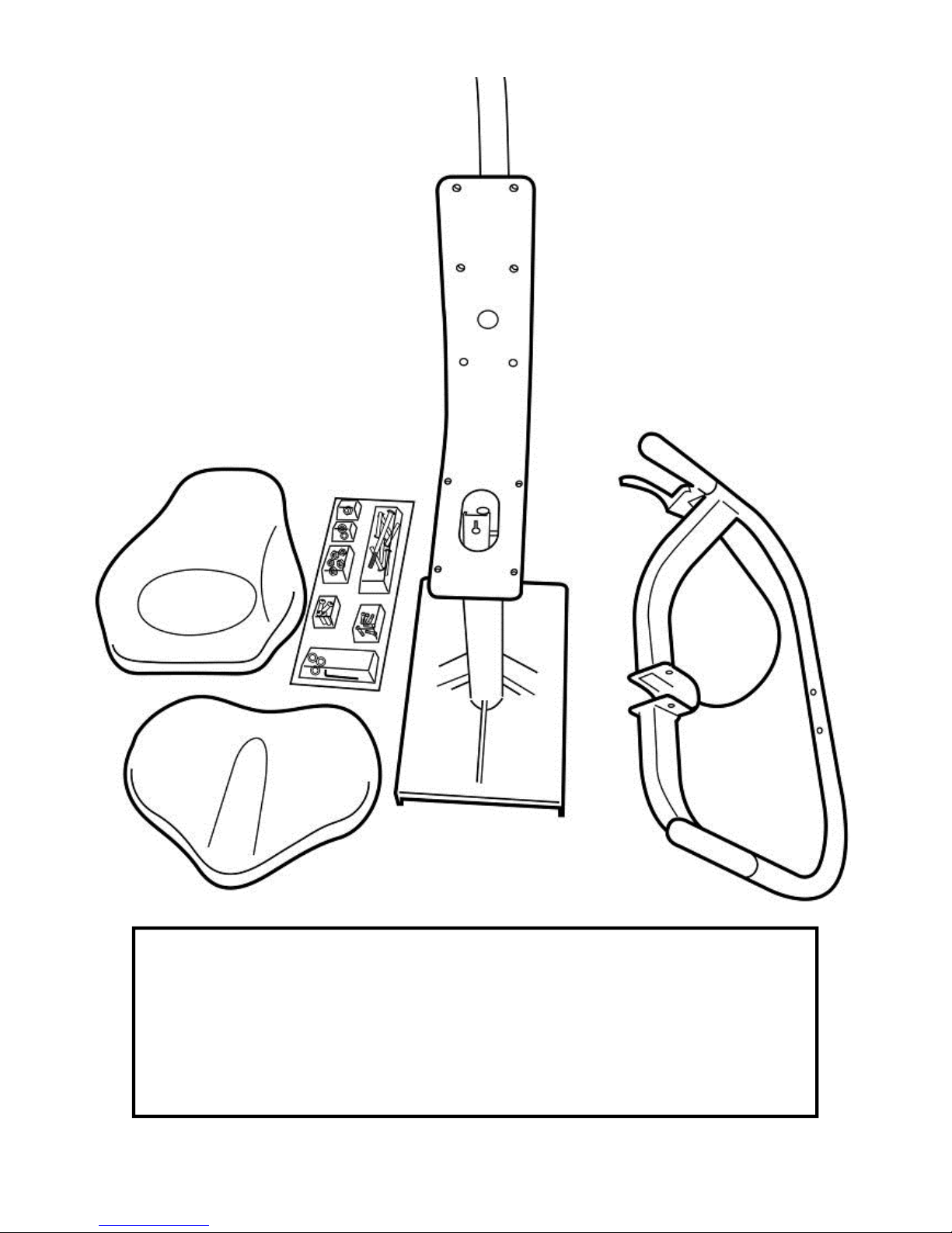
Seat Assembly:
CONTENTS:
1x Seat Main Frame 1x Lower Seat
1x Armrest Assembly 1x Upper Seat back
1x Bolt Pack (Note Bolts/Washers/Nuts are for both Seat and Footplate)
Upper Seat
back Bolt Pack
Seat
Armrest Assembly
Seat Main Frame
11
Attaching Armrest to Lower frame
You will need the Lower Frame, Armrest Assembly and the following bolts/
washers/nuts from the bolt Pack:
1x M8x70mm Bolt 3x M8 Nylock Nut
1x M8x25mm Bolt 1x M8 Washer
2x M8x45mm Bolt
Step One: Mount the Armrest onto the Lower frame from behind as shown.
Important! Before securing bolts (see following page), thread the plastic tie
attached to the armrest cable through the hole as shown right.
Plastic tie
12
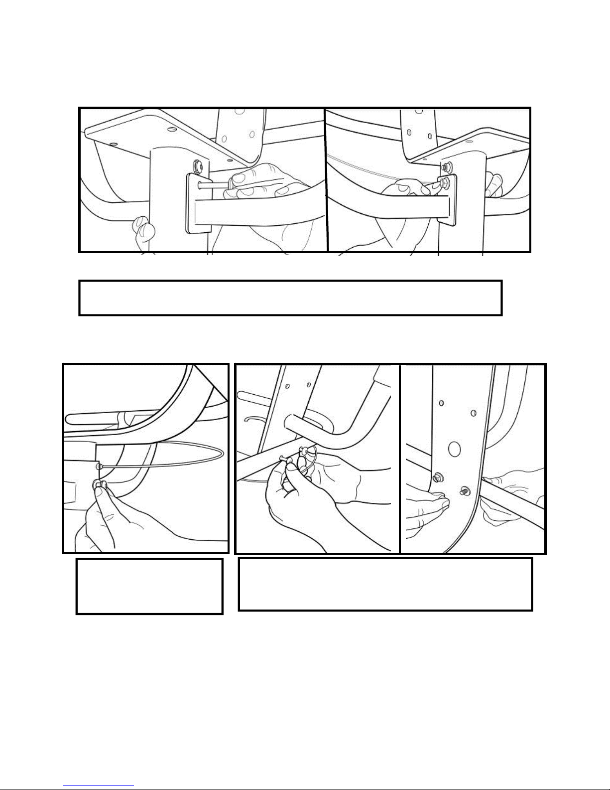
Attaching Armrest to Lower frame:
Step One: Secure Armrest with M8x70mm Bolt, M8 Nylock Nut and M8
Step Three: 2x M8x45mm Bolt,2x Nylock Nut
and 2x M8 Washer
Step Two: M8x25mm
Bolt and M8 Washer
13
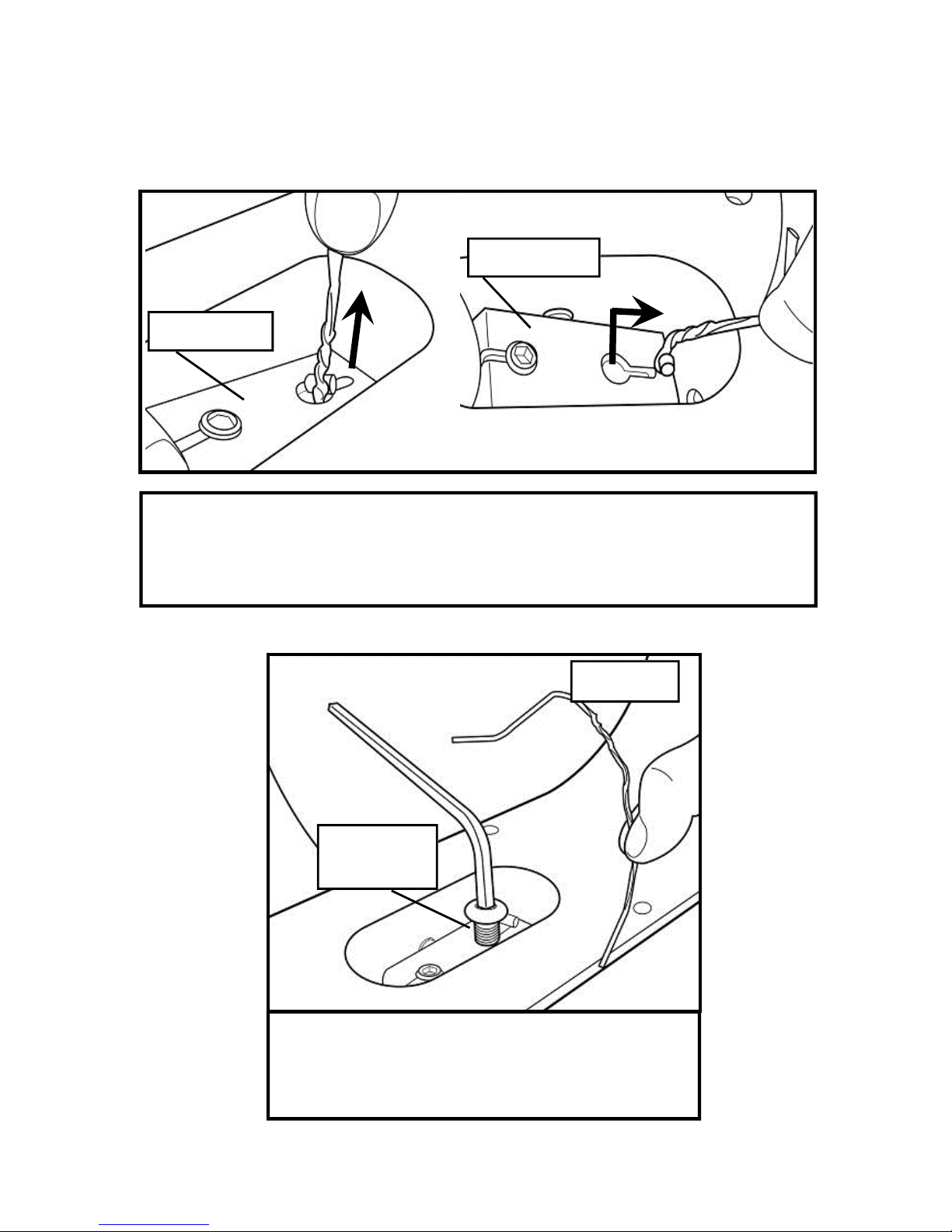
Attaching Armrest cable to Cable Pivot:
Step One: Locate plastic tie, then depress Cable Pivot forward to allow
plastic tie to be pulled through the hole in front. Once the cable end is
through the hole, slide it forward as shown upper right to prevent cable
end from slipping back through.
Step Two: Now secure the cable end with the
M10x25mm bolt. Before tightening the bolt
into position, the plastic tie end can be dis-
carded.
Cable Pivot
Cable Pivot
Plastic tie
M10x25mm
bolt

14
Install Upper Seat Pad with as shown with
4x M6x20mm Bolt/Washer.
Once seat pads are installed the assem-
bly will be complete. Check to be sure
that all bolts are securely tightened and
that the cable lever is functioning normal-
ly.
To mount the seat onto the completed
baseplate assembly, align the seat with
the rear of the T-track and depress cable
lever. Tip: Lift entire seat slightly and
slide onto T-track when level to avoid
binding.
Once seat is on T-track, engage the rear
seat stop for safety.
Seat Frame, Upper/Lower Seat
Install Lower Seat Pad Using 4x
Seat Assembly
Attaching Upper/Lower Seat Pad:

15
The E820 Control Arm
Chain tensioning bolts: Allows for tightening the chain or adjustment from side to side.
Make sure when tightening only to adjust the same amount for both bolts, otherwise the
sprocket will be misaligned.
Note: Tightening the right bolt only will pull the right side of the crank assembly toward
you, tightening the left will pull the left side toward you. Use this feature to realign the
rear with the front sprocket if needed or when changing to a new chain.
Crank arm bolts: Loosen all
8 bolts slightly before ad-
justing/tightening chain.
Inspection plate:
Open to check chain
tension.
Warning:
Do not check
chain tension
with fingers!
Adjuster Knob: Loosen to allow the con-
trol arm to travel through 90 degrees of
travel. Note the telescoping tube is gas
assisted.
Tighten securely when desired workout
position is reached.

16
Yellow
tank
plug
Filling hose and
funnel
Tank Filling and Water Treatment
Open the rear upper
yellow tank plug and
insert hose into tank
(rotating the impeller slightly
may be necessary to allow the
hose to pass), move the tank
adjuster handle to level 20 and
begin filling. Do not fill the
tank higher than the level indi-
cator on the front of the clear
shell. A properly filled tank
holds approximately 8liters of
water.
Warning: Do not under any
circumstances put fingers into
the tank. Use the end of the
hose to
move the impeller should the
need arise.
Note: A large bucket is required for filling (Not included)
In areas where tap water quality is known to be poor, FDF recommends the
use of distilled water.
Note: Lower tank plug is permanently
sealed.
Water Treatment Procedures:
1. Add Chlorine tablet.
2. Enough Chlorine Tablets are supplied
for many years of Water treatment.
Add a chlorine Tablet whenever the
Water appears dirty or cloudy.
WARNING: Only use First Degree
Fitness Supplied Water treatment
tablets.
Use a drop cloth under the tank
when filling the tank to avoid dam-
age floor or carpet
Caution:

17
Long Term Water Treatment and Basic Operation
Caution: It is important that a drop cloth be used under the fluid tank whenever
the tank plug is opened for water treatment.
The level of resistance is determined by the level indicator located on the front of the
tank. Level one indicates lightest resistance, level twenty represents heaviest resistance.
Allow three to four seconds after adjusting resistance handle for the correct resistance
level to be achieved.
Long term water treatment:
Do not use any water treatment other than the tablets supplied with this machine.
For replacement tablets, contact your local First Degree Fitness distributor.
Water treatment schedules for the E820 will vary according to the fluid tanks exposure to
sunlight, but expect 8-12 months near a bright, sunlit window and 2 years or more for a
darker location. At the point of finding the water slightly cloudy, add a Chlorine tablet.
Important: Do not fill past the calibration mark as indicated on the tank level sticker or
water spillage may occur. See tank filling/water treatment page for details.
Resistance:
Use both hands when either raising or lowering the
E820control arm.
Removing hands before the crank comes to a com-
plete stop while training can cause injury. The crank
is direct drive so as to allow both forward and reverse
rotation during workouts.
Warning:
CAUTION
18
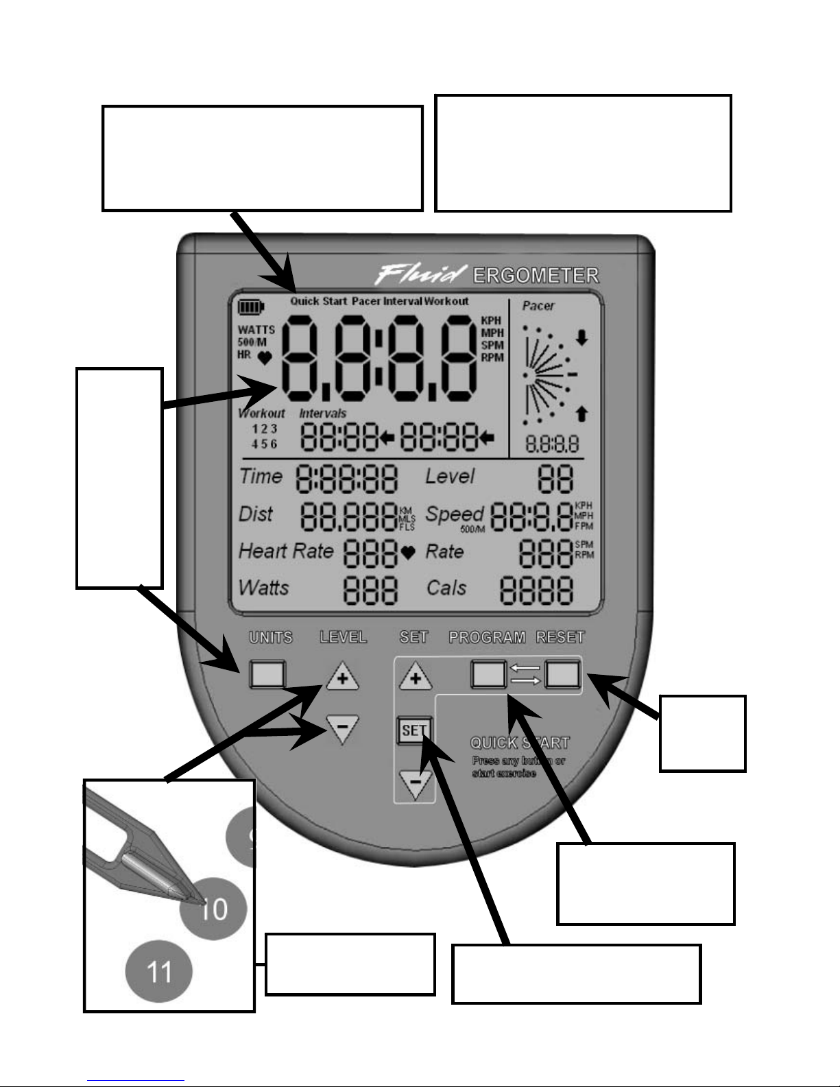
E820 Ergometer.
Quick start provides instant workout
information. Just start training to acti-
vate. You can choose to change
UNITS displayed.
UNITS
displays
WATTS,
RPM,
HR,
MPH,
KPH
Level Adjustable
from 1-20 Set Changes Time, Distance
parameters
Program Clears
current exercise pro-
gram
Note: For complete operation-
al instructions, please refer to
the computer manual, which is
included with your E820.
Reset
Clears
data

19
The USB connectivity now built in to all new models of FDF Console and IPM allow you
to enhance your exercise experience by connecting to your home PC or Laptop. Using
FDF's own sample applications you can exercise while enjoying your favorite movies.
NetAthlon 2 XF for Rowers lets you race with other Internet connected rowers in a Virtual
Reality 3D environment or train solo.
1. Download and Install the USB Device Driver (CDM2xxxx_Setup.exe for 32 and 64 bit
Windows 7/Vista/XP) from the FDF Website.
2. Download and Install the Sample USB Applications from the FDF Website
(www.firstdegreefitness.com).
3 Download and Install NetAthlon 2 XF for Rowers from
http://www.webracing.org/downloads.htm
Note : The NetAthlon Software from WebRacing is not compatible with Cycle XT or
UBE
- The USB Connector is located on the lower rear of the IPM, along with the Sensor
and Heart Rate Monitor Connectors.
- Connect to a Laptop or PC using a standard USB cable, you may need to wait
while Windows starts the USB Device Driver.
Using the First Degree Fitness USB Interface
Description:
Setting up USB connectivity
Connecting your console
Note: Please refer to computer manual where applicable or for further information
refer to our website at www.firstdegreefitness.com

20
Item Timeframe Instructions Notes
Seat and Frame. Weekly. Wipe down weekly with lint
free cloth or more often with
heavy club use.
PK belt tension. Monthly. Check monthly for signs of
slippage. Adjust/tighten as
required.
Tank and water
treatment. 12 months to 2 years. Follow instructions as speci-
fied in the “Water Treatment”
section of this manual.
Chain drive. Check every 100
hours for correct ten-
sion.
Open the inspection plate
and check tension using a
screwdriver or other tool.
Tighten as required using
chain tensioning bolts locat-
ed at the end of the control
arm.
E820 pedals. Tighten weekly using
15mm box wrench
(supplied)
The pedals should be
checked on a regular basis.
A loose pedal can cause
damage to the crank arm
aluminum threads, requiring
replacement.
Maintenance Chart.
Other manuals for fluid e820 Fitness UBE
1
Table of contents
Other First Degree Fitness Elliptical Trainer manuals


