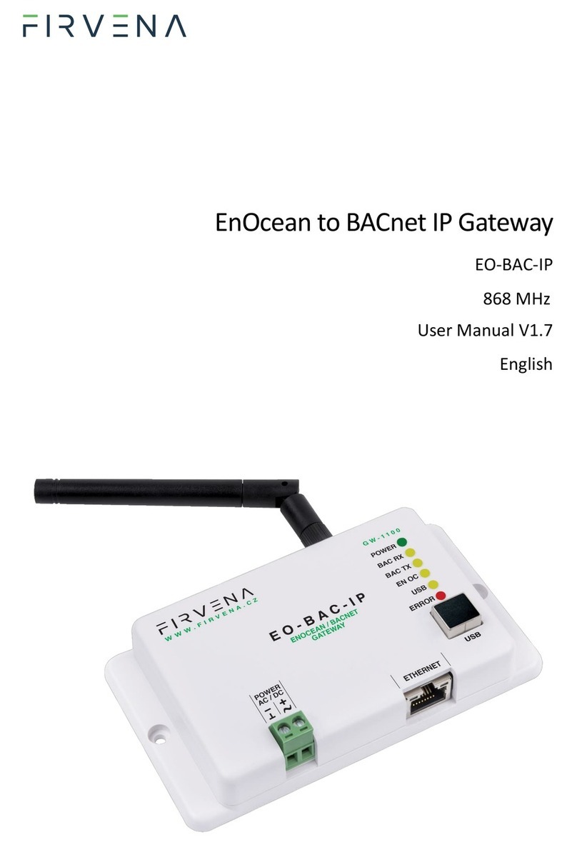
FIRVENA EO-MOD-IP User manual

EnOcean to Modbus TCP/IP Gateway
EO-MOD-IP
868 MHz
User Manual V1.7
English

Contents
EnOcean to Modbus TCP/IP Gateway –User Manual
V1.7 / 2023-11-01 2/40
CONTENTS
Contents.........................................................................................................................................................2
Terms and Abbreviations...............................................................................................................................4
1Introduction............................................................................................................................................5
1.1 Description ......................................................................................................................................5
1.2 Installation instructions...................................................................................................................5
2Hardware Overview................................................................................................................................6
3Technical Data ........................................................................................................................................7
4Safety Information and Warnings ..........................................................................................................8
5Dimensions (in mm)................................................................................................................................9
6Power Supply..........................................................................................................................................9
7Configuration........................................................................................................................................10
7.1 Accessing Web Interface...............................................................................................................10
7.2 Web UI...........................................................................................................................................12
7.2.1 Main Page Overview..............................................................................................................12
7.2.2 Assigning EnOcean elements –unidirectional.......................................................................13
7.2.3 Assigning EnOcean elements –bidirectional.........................................................................14
7.2.4 Assigning Smart ACK devices .................................................................................................14
7.2.5 Definition of Virtual Device....................................................................................................14
7.2.6 Channel Details ......................................................................................................................15
7.2.7 Removing EnOcean elements................................................................................................16
7.2.8 Backup and Restore ...............................................................................................................16
7.3 Steps –How to …...........................................................................................................................17
7.3.1 Enable EnOcean Repeater .....................................................................................................17
8Modbus Interface .................................................................................................................................18
8.1 Mapping of EnOcean Devices........................................................................................................18
8.2 Modbus Registers..........................................................................................................................21
8.2.1 RX Values................................................................................................................................22
8.2.2 TX Values................................................................................................................................23
8.2.3 RX Raw Data...........................................................................................................................24
8.2.4 Channel Config.......................................................................................................................25
8.2.5 Channel Labels .......................................................................................................................25
8.2.6 Value Descriptors...................................................................................................................26

Contents
EnOcean to Modbus TCP/IP Gateway –User Manual
V1.7 / 2023-11-01 3/40
8.3 Supported Function Codes............................................................................................................27
9Firmware Update..................................................................................................................................28
9.1 Over Network................................................................................................................................28
9.2 Over USB........................................................................................................................................28
References ...................................................................................................................................................30
Revision History ...........................................................................................................................................31
ANNEX A Mapping examples of EnOcean devices ................................................................................32
A.1 Basic Examples ..............................................................................................................................32
A.2 RPS Buttons and Switches.............................................................................................................33
A.3 A5-20-01 HVAC Components, Battery Powered Actuator............................................................33
A.4 D2-01-XX Electronic switches and dimmers with Energy Measurement and Local Control ........34
A.4.1 Example with NodOn Micro Smart Plug (D2-01-0E) –Measurements..................................34
A.4.2 Example with NodOn Relay Switch (D2-01-12) –Controlling the output .............................36
A.5 D2-11-XX Bidirectional Room Operating Panel (Smart ACK) ........................................................37
A.5.1 Example with Thermokon SR06 LCD (D2-11-07) ...................................................................37
A.6 D2-15-00 People Activity Sensor...................................................................................................39
ANNEX B Enumeration of Units ................................................................................................................40

Terms and Abbreviations
EnOcean to Modbus TCP/IP Gateway –User Manual
V1.7 / 2023-11-01 4/40
TERMS AND ABBREVIATIONS
Term/Abbr. Explanation
Channel number (CH)............Identifier of EnOcean device within the gateway
DHCP .....................................Dynamic Host Configuration Protocol
EEP.........................................EnOcean Equipment Pofiles
EURID ....................................EnOcean Unique Radio Identifier
Label......................................User-friendly name of EnOcean device
IP ...........................................Internet Protocol
PoE ........................................Power over Ethernet
RX ..........................................Receive, reception
Teach-in.................................Pairing of EnOcean devices
Telegram ...............................EnOcean message
TX ..........................................Transmit, transmission
UPnP......................................Universal Plug and Play
Value index............................Identifier of a data unit within the channel
THANK YOU
Thank you for purchasing our product! We believe in your satisfaction with the product that aligns with the
company philosophy of the highest care and precision. In case of interesting ideas and concepts, please
www.firvena.com

Introduction
EnOcean to Modbus TCP/IP Gateway –User Manual
V1.7 / 2023-11-01 5/40
1INTRODUCTION
1.1 Description
The EO-MOD-IP device is a gateway between EnOcean and Modbus/IP communication protocols. The
EnOcean is a set of technologies and communication protocol that enables the use of wireless and battery-
free sensors, switches and actuators. The Modbus is a communication protocol that is simple to implement
and is widely used in building automation systems. The EO-MOD-IP gateway can receive data from up to 40
EnOcean devices, store it and provide it through the Modbus interface to other devices connected to the
network. It also allows bidirectional communication of EnOcean actuators such as switches, dimmers or
heating valve controllers.
The first part, the manual describes the hardware of the gateway. Chapter 7 contains brief instructions for
configuring the gateway, especially for connecting EnOcean devices. Chapter 8 describes the Modbus
interface and explains how EnOcean devices are mapped to Modbus registers. For firmware update
procedure refer to Chapter 9.
1.2 Installation instructions
The gateway is fixed by using plastic anchors and Phillips
screws to the wall or solid surfaces of suspended
ceilings making sure that it is in a good radio position for
receiving and transmitting signals. When located in
shielded surfaces, the standard supplied antenna can be
replaced with another permitted antenna type for the
868 MHz frequency with an SMA (Male) connector.
External antenna with cable and magnetic base, type
ANT-A1-SMA868-MAG2M is available at the
manufacturer or distributor.

Hardware Overview
EnOcean to Modbus TCP/IP Gateway –User Manual
V1.7 / 2023-11-01 6/40
2HARDWARE OVERVIEW
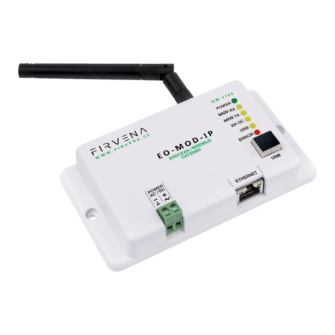
On the front panel, there are a power connector, RJ45 Ethernet connector, type B USB connector, antenna
connector and LED indicators. The USB connector can be used for configuration and firmware update, and
is also used by the EO-BAC Tool application. The green POWER terminal block is removable, making it easier
to handle the device when cables are connected.
The LEDs indicate: the connection of power supply
(POWER), activity in the Modbus network (MOD
RX, MOD TX), activity in the EnOcean wireless
network (ENOC), USB communication (USB) and
error states (ERROR). The LEDs are very useful
when testing or commissioning but because the
emitted light can be disruptive during normal
operation, the LEDs can be deactivated (Web UI >
Settings > LED Indication).
There is a switch to the right of the POWER
terminal block that is only accessible after pulling
out the POWER terminal block. This is used to set
the USB interface mode:
•the “HID” position (default) allows the connection of EO-BAC Tool application
•the “MSC” position allows access to filesystem
Case
LEDs
Behavior
Meaning
Power supply
POWER
Shining
Power supply connected and program running
DHCP
POWER
Goes off for 1 s
Network settings obtained from DHCP server
Modbus
communication
MOD RX
Short blink
Communication in the Modbus network –received a
packet
MOD TX
Short blink
Communication in the Modbus network –sent a
packet
EnOcean
ENOC
Short blink
EnOcean telegram received or sent
USB
USB
Flashing irregularly
Indicates communication through the USB port
–
ERROR
Flashing regularly
A fatal error has occurred, the device is about to
restart

Technical Data
EnOcean to Modbus TCP/IP Gateway –User Manual
V1.7 / 2023-11-01 7/40
3TECHNICAL DATA
Category
Parameter
Value
Product
Product name
EO-MOD-IP
Product title
EnOcean to Modbus TCP/IP Gateway
Product ID
11.2
Vendor name
FIRVENA s.r.o.
Electrical data
Rated supply voltage
24 V DC / 24 V AC
Supply voltage range
10–32 V DC / 24 V AC (10 %)
Rated input current
80 mA / 24 V
Rated input power
1.92 W / 24 V; PoE Active 1.8 W
Ethernet
(Modbus/IP)
Speed
10, 100 Mbit/s
Connector
RJ45
PoE
PoE power supply
According to standard 802.3af, ACTIVE only
EnOcean
Frequency
868 MHz
Maximum number of handled
devices
40 (max. 20 with SmartACK)
Repeater
USB
Device class
Custom HID or Mass Storage
Connector
Type B
Operating conditions
IP Code
IP20
Operating temperature
−20 to +70 °C
Relative humidity
max. 80 %
Dimensions in mm
Dimensions without antenna
Width=126, Height=71, Depth=25
Weight
Weight without antenna
115 g
Box material
ABS, white
Product conformity and certification
ROHS Directive
The device is manufactured in accordance with the directive 2015/863/EU (RoHS 3) of the
European Parliament and of the Council on the restriction of the use of certain hazardous
substances in electrical and electronic equipment.
EMC - Declaration of Conformity
The device is compliant with the directive 2014/53/EU, 2011/65/EU RoHS.
Approvals tests ČSN EN 55032, ČSN EN 55035, ČSN EN 6100-4-2, ČSN EN 6100-4-3, ČSN EN
6100-4-4, ČSN EN 6100-4-5, ČSN EN 6100-4-6, ČSN EN 6100-4-11, ČSN EN IEC 6100-6-2.
UK Conformity Assessed (UKCA)
The device is compliant with the British Legislation UK Conformity Assessed (UKCA) and
meets all relevant requirements.
EnOcean Technology
The device is fully compatible with the EnOcean radio protocol and as such is certified by
the EnOcean Alliance Level 2.

Safety Information and Warnings
EnOcean to Modbus TCP/IP Gateway –User Manual
V1.7 / 2023-11-01 8/40
4SAFETY INFORMATION AND WARNINGS
Please follow the general safety regulations. This device may only be installed by a qualified person
(accredited electrician) and after reading these instructions. Improper installation can result in
health, property or equipment damage.
The product meets the general safety regulations. The protection Cover IP 20 allows installation only in
normal, dry space.
The gateway must be powered from a safe voltage source that meets the requirements for input voltage
range and must be installed in accordance with national and general safety standards.
Follow the safety instructions and applicable standards for the country and location of installation. The
product may only be used in accordance with this manual.
To avoid the risk of electrical shock or fire, the maximum operating parameters of the gateway must not be
exceeded.
Use only unmodified products.
Only cable types with sufficient cross-section and insulation properties may be used for the connection.
STORAGE
The device must be stored in a temperature range 0-40 °C and a relative humidity of up to 80 %, and non-
condensing spaces. Products must not be exposed shock, harmful vapors or gases.
REPAIRS
Products are repaired by the manufacturer. Products to be repaired are shipped in a package that ensures
shock absorption and protects the products against damage during shipment.
WARRANTY
The product is warranted 24 months from the date of delivery that is mentioned on the delivery note. The
manufacturer only guarantees properties and parameters that are explicitly described in the technical
documentation. Claims, complaints and returns must be directed exclusively to the manufacturer. The
complaint must contain the exact product identification, delivery note number and defects description. The
manufacturer is not responsible for defects caused by improper storage, improper external connection,
damages caused by external influences especially due to unacceptable size, incorrect adjustment, improper
installation, incorrect operation or normal wear and tear.
PRODUCT DISPOSAL
The product does not belong to municipal waste. The product must be disposed to the separate
waste collection with the possibility of recycling, according to local regulations and legislation.
The product contains electronic components.

Dimensions (in mm) / Power Supply
EnOcean to Modbus TCP/IP Gateway –User Manual
V1.7 / 2023-11-01 9/40
5DIMENSIONS (IN MM)
6POWER SUPPLY
There are two possible power supply connections:
1. Power supply via PoE (Power over Ethernet):
The device supports PoE according to the
802.3af standard. Network elements must
support this type of power interface. Passive
PoE is not possible through the ETHERNET
input. For passive PoE power supply, we
recommend to use an appropriate splitter
cable with connection to the POWER input.
2. Power supply from an external source:
The gateway must be powered from a safe
voltage source that meets input voltage range
requirements. The electrical installation must
be in accordance with national requirements
and safety standards.

Configuration
EnOcean to Modbus TCP/IP Gateway –User Manual
V1.7 / 2023-11-01 10/40
7CONFIGURATION
The gateway has an integrated web application (Web UI) that serves to configure it using a web browser.
Alternatively, a desktop application EO-BAC Tool is available at www.firvena.com, ->
SUPPORT/DOWNLOAD/EO-MOD-IP/APPLICATION, it requires USB connection to the gateway and Windows
7 or higher. The use of EO-BAC Tool becomes necessary, among other things, if the password to Web UI has
been forgotten. The following part describes how to open Web UI for the first time.
7.1 Accessing Web Interface
The IP address factory setting is:
Switch on the gateway and connect it to a local network via the
ETHERNET connector or directly to a computer with an Ethernet
adapter. The DHCP client is enabled by default, so the gateway
automatically obtains the IP address and other network parameters
from a DHCP server if available. The gateway signals DHCP success by
shortly turning off the green POWER light.
If the configuration via DHCP fails, because there is no DHCP server in
the network or you connect the gateway directly to a computer, the default network configuration is used
after 10 seconds. In this case, change Ethernet adapter settings so that your computer has the same subnet
mask and a different IP address, e.g. 192.168.1.95.
The Web UI is available on HTTP port 80, if you
know the IP address of the gateway, simply
enter “http://<IP Address>” into the address
bar of your web browser (e.g.
http://192.168.1.90).
The main page opens in “view-only mode”. Login is required for other
pages and configuration changes. The default password is “123”, you can
change it in [Settings > Change Password]. If the password is lost, you need
to perform a factory reset using the EO-BAC Tool.
There are several options to find out the currently valid IP of the gateway:
1. Network Discovery using UPnP
This method is recommended when using the Microsoft Windows
operating system and UPnP messages are allowed in the network to which
the gateway is connected.
Open the Network item in the File Explorer:
PARAMETER
VALUE
IP address
192.168.1.90
Subnet mask
255.255.255.0
Default gateway
192.168.1.1
DHCP
enabled

Configuration
EnOcean to Modbus TCP/IP Gateway –User Manual
V1.7 / 2023-11-01 11/40
The gateway is under the group “Other Devices”.
The description and IP address of the gateway are
shown. Double click on the device item to open
the Web UI. [Right click > Properties] will display
additional information.
If the gateway is not shown, try to refresh the list:
[Click on the list > press F5 key] or [Right click > Refresh].
2. Using EO-BAC Tool
In the USB HID mode (see Ch. 2), the gateway presents itself as a Custom
HID USB device. Connect the gateway to your computer using USB and
use the EO-BAC Tool.
3. USB MSC
In the USB MSC mode (see Ch. 2), the gateway presents itself as an
external USB drive. Connect the gateway to your computer using USB.
Find a file named NETINFO.TXT in the root directory and open it. The file
contains the current IP address. To access the Web UI, enter the IP address to the address bar of your web
browser.

Configuration
EnOcean to Modbus TCP/IP Gateway –User Manual
V1.7 / 2023-11-01 12/40
4. DHCP server
If you have access to the local DHCP server (usually through the configuration interface of your router), the
IP address should be in DHCP clients list, look for the host name “EO-MOD-IP_XXXXXX”. To access the Web UI,
enter the IP address to the address bar of your web browser.
7.2 Web UI
This chapter is a brief guide to the use of the Web UI application.
The Web UI is used to configure the gateway. The main purpose of the application is to manage EnOcean
devices connected to the gateway. The application is also a useful verification tool whereby you can evaluate
whether your system works well. It allows to see the states, measured quantities, communication intervals
or signal strength of the connected EnOcean devices.
7.2.1 Main Page Overview
1. Dashboard –overview of
configured channels
2. Toggles dashboard view:
•Detailed –more
information, only
configured channels
are displayed
•Condensed –less
information, both
configured and empty
channels are displayed
3. Menu items:
•Add new device
•Settings
•Telegram log
4. Login button:
•Locked –configuration
locked and cannot be
changed, only dashboard is accessible
•Unlocked –configuration of the gateway can be changed
5. Gateway identification
The main page is accessible without a password. The default password is “123”, you can change it in [Settings
> Change Password].

Configuration
EnOcean to Modbus TCP/IP Gateway –User Manual
V1.7 / 2023-11-01 13/40
7.2.2 Assigning EnOcean elements –unidirectional
This teach-in procedure is only applicable for unidirectional communication when the gateway only receives
data.
Let’s have a humidity sensor (A5-04-01) we want to assign to the channel 1. The procedure is as follows:
1. Click the “Add new” icon, a
dialog box appears.
2. Push the pairing button to
transmit a teach-in telegram.
3. The received telegram is
displayed in the dialog box.
4. Select the channel number 1.
5. Click “Save” to confirm
changes
6. Now the sensor is assigned
to channel 1 and its data is
available through the
Modbus interface.
Optionally, the Label can be set for the device. The Label text is used in the Channel labels registers (see Ch.
8.2.5). If the Label field is left empty, the default text will be used.
The knowledge of EEP allows the gateway to interpret the received data correctly. Some types of EnOcean
devices do not provide the EEP information in their teach-in telegram or even not have a special telegram
for teach-in (e.g. buttons and switches). In that case, the EEP must be set manually, it is usually given by a
label on the device or a datasheet.
Devices can also by assigned manually by entering the ID and EEP.
Click on the channel box to view more settings and status information:

Configuration
EnOcean to Modbus TCP/IP Gateway –User Manual
V1.7 / 2023-11-01 14/40
7.2.3 Assigning EnOcean elements –bidirectional
This teach-in procedure is applicable for EnOcean devices with bidirectional communication profiles when
the gateway is supposed to receive data from the device and also transmit data to the assigned device.
Let’s have a valve actuator (A5-20-01) we want to assign to the channel 1. The procedure is as follows:
1. Click the “Add new” icon, a dialog box appears.
2. Check “LRN enable”
3. Select the channel number 1.
Channel 1 is now in the teach-in mode.
4. Push the pairing button to transmit a teach-in telegram from the actuator.
5. Gateway receives the telegram and sends a teach-in response.
6. The device is automatically saved to the selected channel and its data is available through the Modbus
interface.
To change the Label, enter the new text and click “Save”.
Notes:
•The device being assigned usually signals successful teach-in, e.g. by flashing LED. If it signals an error, the
teach-in must be repeated.
7.2.4 Assigning Smart ACK devices
To assign a Smart ACK device to the gateway, the procedure is the same as for bidirectional profiles (7.2.3).
Repeaters are not supported, there must be a direct connection between the gateway and the Smart ACK
device.
7.2.5 Definition of Virtual Device
The gateway can be used to simulate a real EnOcean device. This function is necessary when controlling
actuators that do not implement any bidirectional profile, typically some types of relay switches.
For example, we want to control a relay switch that supports reception of a Door/Window Contact D5-00-
01. The procedure is as follows.

Configuration
EnOcean to Modbus TCP/IP Gateway –User Manual
V1.7 / 2023-11-01 15/40
First, define a virtual device of type D5-00-01, for example at channel 1:
1. Click the “Add new” icon, a dialog box
appears.
2. Check “Simulate device”
3. Select a channel number (channel 1)
4. Select the type of device (D5-00-01)
5. Click “Save” to confirm changes
6. The device is saved to the selected
channel and its data is available
through the Modbus interface.
Second, pair the virtual device with the
relay switch:
1. Click on the channel 1 box to see
channel details
2. Put the relay switch to the pairing mode (follow the procedure given by the manufacturer of the switch)
3. In channel details click on the “Send LRN” button
4. The gateway will transmit a teach-in telegram of the virtual device
5. The switch will receive the teach-in telegram and save the virtual device
Third, test the connection:
1. Navigate to [Edit channel > Values]
2. Set the data to be transmitted (0:closed or
1:open)
3. Use “Send Now” to transmit a data telegram
Notes:
•Each virtual device must have a unique ID,
This is given by the MyID setting.
•To enable receiving the actual state of the switch,
assign it to a different channel.
7.2.6 Channel Details
When you click on the channel box, the “Edit channel” view is shown. There are three tabs:
1. Settings –configuration of the channel
2. Values –actual data of the assigned device
3. History –short history of the first three RX values
In the channel box, the first three RX values are displayed. To view all actual data of the assigned device,
open the “Values” tab. Here you can find:
1. Address of the Modbus register
2. Value name and range info
3. Actual data
4. Actual data encoded to registers

Configuration
EnOcean to Modbus TCP/IP Gateway –User Manual
V1.7 / 2023-11-01 16/40
For bidirectional EEPs and virtual devices, TX data can also be entered and sent using this view.
7.2.7 Removing EnOcean elements
1. Click on a channel box.
2. Click on the “Delete” button.
To remove all elements, use [Settings > Factory Reset > Reset Channels].
7.2.8 Backup and Restore
The configuration of the gateway can be exported to a file for later recovery or reuse. The backup file is
compatible with the file used by EO-BAC Tool application.
To back up the configuration:
1. Navigate to [Settings > Backup and Restore].
2. Click on Download.
3. A file named config.json is downloaded.
To restore the configuration:
1. Navigate to [Settings > Backup and Restore].
2. Select a file or drag it to the dashed rectangle.
3. Click on Upload.
Notes:
•Only channels are restored, the “Gateway Settings” are preserved.
1.
3.
4.
2.

Configuration
EnOcean to Modbus TCP/IP Gateway –User Manual
V1.7 / 2023-11-01 17/40
7.3 Steps –How to …
7.3.1 Enable EnOcean Repeater
The repeater mode is changed in [Web UI > Settings > EnOcean].
If turned on, the gateway forwards received telegrams in the EnOcean network.
Fig. 7.1 Repeater function
Value
Meaning
1 –OFF (default)
Off
2 –LEVEL1
Level 1 (only original telegrams)
3 –LEVEL2
Level 2 (original and once repeated telegrams)
Value
Meaning

Modbus Interface
EnOcean to Modbus TCP/IP Gateway –User Manual
V1.7 / 2023-11-01 18/40
8MODBUS INTERFACE
The gateway is a Modbus TCP/IP server, it processes requests sent by clients. By default, the Modbus server
listens on TCP port 502 and UDP port 502 (there is a limit of four simultaneous TCP connections). Each
Modbus server may provide different services, which are identified by function codes in Modbus. The
definitions of standard services are described by the application layer specification –see [7], for more
information about Modbus over TCP/IP see [8].
This chapter describes how the data of EnOcean devices is translated into the Modbus data model and how
this data can be accessed by standard function codes. A complete list of Modbus registers is also available.
8.1 Mapping of EnOcean Devices
EnOcean devices are mapped as a set of Modbus registers. The gateway can handle up to 40 EnOcean
devices. To assign an EnOcean device, the teach-in procedure has to be carried out (see Ch. 7.2). The
assigned EnOcean devices are identified by Channel (CH1…40) within the gateway, the Channel is selected
by user during teach-in procedure.
Data fields received in a telegram are divided into individual Modbus registers so that they can be accessed
using Modbus standard functions from the network. The gateway contains a database of supported EnOcean
products, the meaning of individual data registers depends on the type of EnOcean device (EEP) that is
assigned to the channel during teach-in procedure.
Three types of data fields are distinguished:
•Numeric value: usually a measured physical quantity such as temperature, humidity, etc.
•Enumeration: defined as a list of items that express a state or configuration of the device
•Boolean: two-state enumeration whose items can be interpreted as true/false, such as on/off,
enabled/disabled, open/closed, etc.
In addition, two directions are distinguished:
•RX: data received by the gateway (incoming telegrams)
•TX: data transmitted by the gateway (outgoing telegrams)

Modbus Interface
EnOcean to Modbus TCP/IP Gateway –User Manual
V1.7 / 2023-11-01 19/40
The data fields are stored internally as Values. The Values are identified by Value index, 15 Values is reserved
per channel (indexes 0 to 14):
The Values from Telegram data range represent a model of EnOcean telegram. For simple devices (such as
sensors with unidirectional communication) the model of telegram can also be assumed to be a model of
EnOcean device. Some more complex EEP definitions consist of several types of telegrams that represent
different commands, so the device cannot be described by a single telegram. Special mapping is created for
these devices.
For direction “RX”, all used Values are mapped to RX Values registers (starting at address 0). For direction
“TX” all used Values are mapped to TX Values registers (starting at address 1000). If the channel is not
occupied the associated Value registers are zeroed.
The mapped data fields from EnOcean telegram are indexed in the same order as they appear in the EEP
definition –see [3].
Besides the data values, there are also helper values for each channel that provide status information:
Index
Name
Meaning
Value Range
RX
15
Telegram
counter
Number of received telegrams
0…65535 (overflows to zero)
16
Telegram age
Time elapsed since the last telegram
0…65000 s (65535: no telegram, 65001:
range exceeded)
17
Signal
Signal strength (RSSI value measured by the
EnOcean transceiver)
0…−255 dBm
18
reserved
19
Error
Enumeration of channel state and error codes
See Ch. 8.2.1
TX
15
Telegram
counter
Number of sent telegrams
0…65535 (overflows to zero)
16
Telegram age
Time elapsed since the last telegram
0…65000 s (65535: no telegram, 65001:
range exceeded)
17
Send option
Data transmission control
See Ch. 8.2.2
18
reserved

Modbus Interface
EnOcean to Modbus TCP/IP Gateway –User Manual
V1.7 / 2023-11-01 20/40
The table below shows mapping examples for individual EnOcean devices, more examples are also in ANNEX
A.
Register
CH1
Value 1
0
Temperature
A5-02-05
Temperature Sensors, Temperature
Sensor Range 0°C to +40°C
Value 2
1
Value 3
2
Value 4
3
Value 5
4
…
…
…
Value 16
15
T. Counter
Value 17
16
T. Age
Value 18
17
Signal
Value 19
18
Value 20
19
Error
CH2
Value 1
0
Humidity
A5-09-04
Gas Sensor, CO2 Sensor
Value 2
1
Concentration
Value 3
2
Temperature
Value 4
3
H-Sensor
Value 5
4
T-Sensor
…
…
…
Value 16
15
T. Counter
Value 17
16
T. Age
Value 18
17
Signal
Value 19
18
Value 20
19
Error
…
CH40
Value 1
0
Power Fail
D2-32-02
A.C. Current Clamp, 3 channels
Value 2
1
Divisor
Value 3
2
Channel 1
Value 4
3
Channel 2
Value 5
4
Channel 3
…
…
…
Value 16
15
T. Counter
Value 17
16
T. Age
Value 18
17
Signal
Value 19
18
Value 20
19
Error
Other manuals for EO-MOD-IP
1
Table of contents
Other FIRVENA Gateway manuals
