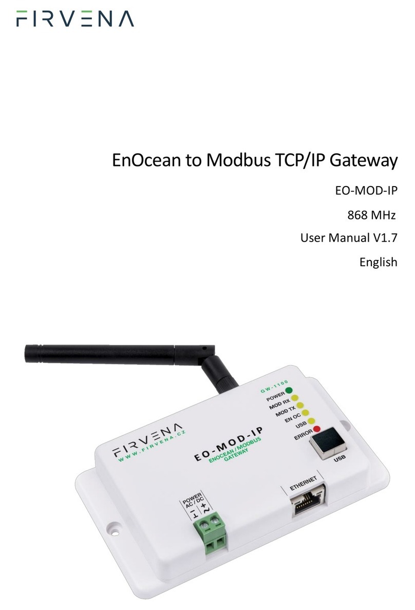
FIRVENA EO-MOD-IP User manual

EnOcean to Modbus/IP Gateway
EO-MOD-IP
User Manual V1.2
English

Contents
EnOcean to Modbus/IP Gateway –User Manual
V1.2 / 2022-11-04 2/38
Contents
Contents .................................................................................................................................................. 2
Terms and Abbreviations ........................................................................................................................ 4
List of Figures and Tables ........................................................................................................................ 5
1 Introduction..................................................................................................................................... 6
2 Hardware Overview......................................................................................................................... 7
3 Technical Data ................................................................................................................................. 8
4 Modbus Interface.......................................................................................................................... 10
4.1 Mapping of EnOcean Devices................................................................................................ 10
4.2 Connection to Modbus Server............................................................................................... 13
4.3 Supported Function Codes .................................................................................................... 13
4.4 Modbus Registers.................................................................................................................. 14
4.4.1 RX Values....................................................................................................................... 14
4.4.2 TX Values ....................................................................................................................... 15
4.4.3 RX Raw Data .................................................................................................................. 16
4.4.4 Channel Config............................................................................................................... 17
4.4.5 Channel Labels............................................................................................................... 18
4.4.6 Value Descriptors .......................................................................................................... 19
5 Configuration................................................................................................................................. 20
5.1 Device Discovery.................................................................................................................... 20
5.2 Web UI................................................................................................................................... 22
5.2.1 Main Page Overview...................................................................................................... 22
5.2.2 Assigning EnOcean elements –unidirectional .............................................................. 23
5.2.3 Assigning EnOcean elements –bidirectional ................................................................ 24
5.2.4 Assigning Smart ACK devices......................................................................................... 25
5.2.5 Definition of Virtual Device ........................................................................................... 25
5.2.6 Removing EnOcean elements........................................................................................ 26
5.2.7 Backup and Restore....................................................................................................... 27
6 Firmware Update........................................................................................................................... 28
6.1 Over Network ........................................................................................................................ 28
6.2 Over USB................................................................................................................................ 29
References............................................................................................................................................. 30
Revision History..................................................................................................................................... 31

Contents
EnOcean to Modbus/IP Gateway –User Manual
V1.2 / 2022-11-04 3/38
ANNEX A Mapping examples of EnOcean devices............................................................................ 32
A.1 Basic Examples ...................................................................................................................... 32
A.2 RPS Buttons and Switches ..................................................................................................... 33
A.3 A5-20-01 HVAC Components, Battery Powered Actuator .................................................... 33
A.4 D2-01-12 Electronic switches and dimmers with Energy Measurement and Local Control,
Type 0x12 .......................................................................................................................................... 34
A.5 D2-11-07 Bidirectional Room Operating Panel (Smart ACK)................................................. 35
A.6 D2-15-00 People Activity Sensor........................................................................................... 37
ANNEX B Enumeration of Units ........................................................................................................ 38

Terms and Abbreviations
EnOcean to Modbus/IP Gateway –User Manual
V1.2 / 2022-11-04 4/38
Terms and Abbreviations
Term/Abbr. Explanation
Channel number (CH)................Identifier of EnOcean device within the gateway
DHCP..........................................Dynamic Host Configuration Protocol
EEP.............................................EnOcean Equipment Pofiles
EURID.........................................EnOcean Unique Radio Identifier
Label ..........................................User-friendly name of EnOcean device
IP................................................Internet Protocol
PoE.............................................Power over Ethernet
RX...............................................Receive, reception
Teach-in.....................................Pairing of EnOcean devices
Telegram....................................EnOcean message
TX...............................................Transmit, transmission
UPnP..........................................Universal Plug and Play
Value index................................Identifier of a data unit within the channel

List of Figures and Tables
EnOcean to Modbus/IP Gateway –User Manual
V1.2 / 2022-11-04 5/38
List of Figures and Tables
Figures
Fig. 1.1 Functional overview.................................................................................................................... 6
Fig. 2.1 Gateway overview –front side................................................................................................... 7
Fig. 2.2 Gateway overview –meaning of manual switches .................................................................... 7
Fig. 4.1 Conversion of data.................................................................................................................... 10
Fig. 4.2 Values........................................................................................................................................ 11
Fig. 4.3 Mapping of EnOcean devices.................................................................................................... 12
Fig. 5.1 Main page overview.................................................................................................................. 22
Fig. 5.2 Adding elements –teach-in procedure .................................................................................... 23
Fig. 5.3 Adding elements –manually .................................................................................................... 24
Fig. 5.4 Adding elements –bidirectional teach-in procedure ............................................................... 25
Fig. 5.5 Adding elements –virtual device.............................................................................................. 26
Fig. 5.6 Virtual device –send teach-in telegram................................................................................... 26
Tables
Tab. 3.1 Technical data............................................................................................................................ 8
Tab. 4.1 Helper values........................................................................................................................... 11
Tab. 4.2 Supported Modbus functions.................................................................................................. 13
Tab. 4.3 Register map............................................................................................................................ 14
Tab. 4.4 RX Values ................................................................................................................................. 15
Tab. 4.5 RX Values –Error register........................................................................................................ 15
Tab. 4.6 TX Values ................................................................................................................................. 16
Tab. 4.7 TX Values –Send option register............................................................................................. 16
Tab. 4.8 Raw data –RPS, 1BS ................................................................................................................ 16
Tab. 4.9 Raw data –4BS ........................................................................................................................ 17
Tab. 4.10 Raw data –VLD, MSC............................................................................................................. 17
Tab. 4.11 Channel config....................................................................................................................... 17
Tab. 4.12 Channel labels........................................................................................................................ 18
Tab. 4.13 Value descriptors................................................................................................................... 19

Introduction
EnOcean to Modbus/IP Gateway –User Manual
V1.2 / 2022-11-04 6/38
1Introduction
The EO-MOD-IP device is a gateway between EnOcean and Modbus/IP communication protocols
(Fig. 1.1). The EnOcean is a set of technologies and communication protocol that enables the use of
wireless and batteryless sensors, switches and actuators. The Modbus is a communication protocol
that is simple to implement and is widely used in building automation systems. The EO-MOD-IP
gateway can receive data from up to 40 EnOcean devices, store it and provide it through the Modbus
interface to other devices connected to the network.
The first part of this manual describes the hardware of the gateway. Chapter 4 describes the Modbus
interface and explains how EnOcean devices are mapped to Modbus registers. Chapter 5 contains brief
instructions for configuring the gateway, especially for connecting EnOcean devices. For firmware
update procedure refer to Chapter 6.
Fig. 1.1 Functional overview

Hardware Overview
EnOcean to Modbus/IP Gateway –User Manual
V1.2 / 2022-11-04 7/38
2Hardware Overview
There is a power connector, RJ45 Ethernet connector, type B USB connector, antenna connector and
LED indicators on the front panel (Fig. 2.1). The LEDs indicates the connection of power supply
(POWER), traffic in the Modbus network (MOD RX, MOD TX), traffic in the EnOcean wireless network
(ENOC), communication through the USB interface (USB) and error states (ERROR). The USB connector
is used for configuration and firmware update, it is used by the EO-BAC Tool configuration application.
The green POWER connector is removable, which simplifies device handling if wires are connected.
Fig. 2.1 Gateway overview –front side
There is a switch to the right of the POWER connector that is accessible after pulling out the
POWER connector (Fig. 2.2). It sets the USB interface mode:
the “HID” position (default) allows the EO-BAC Tool application to be connected
the “MSC” position activates the firmware update mode (see Ch. 6.2)
Fig. 2.2 Gateway overview –meaning of manual switches

Technical Data
EnOcean to Modbus/IP Gateway –User Manual
V1.2 / 2022-11-04 8/38
3Technical Data
Tab. 3.1 Technical data
Category
Parameter
Value
Product
Product name
EO-MOD-IP
Product title
EnOcean to Modbus/IP Gateway
Product ID
11.2
Vendor name
FIRVENA s.r.o.
Electrical data
Rated supply voltage
24 V DC / 24 V AC
Supply voltage range
10–32 V DC / 24 V AC (10 %)
Rated input current
50 mA
Rated input power
1.2 W
Ethernet
(Modbus/IP)
Speed
10, 100 Mbit/s
Connector
RJ45
PoE
(pins 4, 5, 7, 8)
PoE supply powering
According to standard 802.3af
EnOcean
Frequency
868 MHz
Maximum number of handled
devices
40 (max. 20 with SmartACK)
Repeater
USB
Device class
Custom HID or Mass Storage
Connector
Type B
Operating
conditions
IP Code
IP20
Operating temperature
20 to 70 °C
Relative humidity
max. 80 %
Dimensions in mm
Dimensions without antenna
Width=126, Height=71, Depth=25
Weight
Weight without antenna
115 g
Box material
ABS, white
EMC
In accordance with the directive
2014/53/EU, 2011/65/EU RoHS
EMC
Approvals tests
ČSN EN 55032, ČSN EN 55035, ČSN EN 6100-4-2, ČSN EN
6100-4-3, ČSN EN 6100-4-4, ČSN EN 6100-4-5, ČSN EN
6100-4-6, ČSN EN 6100-4-11, ČSN EN IEC 6100-6-2

Technical Data
EnOcean to Modbus/IP Gateway –User Manual
V1.2 / 2022-11-04 9/38
Dimensions in mm:

Modbus Interface
EnOcean to Modbus/IP Gateway –User Manual
V1.2 / 2022-11-04 10/38
4Modbus Interface
4.1 Mapping of EnOcean Devices
EnOcean devices are mapped as a set of Modbus registers. The gateway can handle up to 40 EnOcean
devices. To assign an EnOcean device, the teach-in procedure has to be carried out (see Ch. 5.2). The
assigned EnOcean devices are identified by Channel (CH1…40) within the gateway, the Channel is
selected by user during teach-in procedure.
Data fields received in a telegram are divided into individual Modbus registers so that they can be
accessed using Modbus standard functions from the network –see Fig. 4.1. The gateway contains a
database of supported EnOcean products, objects are created depending on the type of EnOcean
device (EEP) that is assigned to the channel during teach-in procedure.
Fig. 4.1 Conversion of data
Three types of data fields are distinguished:
Numeric value: usually a measured physical quantity such as temperature, humidity, etc.
Enumeration: defined as a list of items that express a state or configuration of the device
Boolean: two-state enumeration whose items can be interpreted as true/false, such as on/off,
enabled/disabled, open/closed, etc.
In addition, two directions are distinguished:
RX: data received by the gateway (incoming telegrams)
TX: data transmitted by the gateway (outgoing telegrams)
The data fields are stored internally as Values. The Values are identified by Value index, 15 Values is
reserved per channel (indexes 0 to 14) –see Fig. 4.2 and Fig. 4.3.
The Values from Telegram data range represent a model of EnOcean telegram. For simple devices
(such as sensors with unidirectional communication) the model of telegram can also be assumed to be
a model of EnOcean device. Some more complex EEP definitions consist of several types of telegrams

Modbus Interface
EnOcean to Modbus/IP Gateway –User Manual
V1.2 / 2022-11-04 11/38
that represent different commands, so the device cannot be described by a single telegram. Special
mapping is created for these devices.
For direction “RX”, all used Values are mapped to RX Values registers (starting at address 0). For
direction “TX” all used Values are mapped to TX Values registers (starting at address 1000). If the
channel is not occupied the associated Value registers are zeroed.
The mapped data fields from EnOcean telegram are indexed in the same order as they appear in the
EEP definition –see [3].
Besides the data values, there are also helper values for each channel that provide status information
–see Tab. 4.1.
Tab. 4.1 Helper values
Index
Name
Meaning
Value Range
RX
15
Telegram
counter
Number of received telegrams
0…65535 (overflows to zero)
16
Telegram age
Time elapsed since the last telegram
0…65000 s (65535: no telegram, 65001:
range exceeded)
17
Signal
Signal strength (RSSI value measured by the
EnOcean transceiver)
0…255 dBm
18
reserved
19
Error
Enumeration of channel state and error codes
See Tab. 4.5
TX
15
Telegram
counter
Number of sent telegrams
0…65535 (overflows to zero)
16
Telegram age
Time elapsed since the last telegram
0…65000 s (65535: no telegram, 65001:
range exceeded)
17
Send option
Data transmission control
See Tab. 4.7
18
reserved
Examples of mapping for individual EnOcean devices can be found in ANNEX A.
Fig. 4.2 Values

Modbus Interface
EnOcean to Modbus/IP Gateway –User Manual
V1.2 / 2022-11-04 12/38
Register
CH1
Value 1
0
Temperature
A5-02-05
Temperature Sensors, Temperature Sensor Range
0°C to +40°C
Value 2
1
Value 3
2
Value 4
3
Value 5
4
…
…
…
Value 16
15
T. Counter
Value 17
16
T. Age
Value 18
17
Signal
Value 19
18
Value 20
19
Error
CH2
Value 1
0
Humidity
A5-09-04
Gas Sensor, CO2 Sensor
Value 2
1
Concentration
Value 3
2
Temperature
Value 4
3
H-Sensor
Value 5
4
T-Sensor
…
…
…
Value 16
15
T. Counter
Value 17
16
T. Age
Value 18
17
Signal
Value 19
18
Value 20
19
Error
…
CH40
Value 1
0
Power Fail
D2-32-02
A.C. Current Clamp, 3 channels
Value 2
1
Divisor
Value 3
2
Channel 1
Value 4
3
Channel 2
Value 5
4
Channel 3
…
…
…
Value 16
15
T. Counter
Value 17
16
T. Age
Value 18
17
Signal
Value 19
18
Value 20
19
Error
Fig. 4.3 Mapping of EnOcean devices

Modbus Interface
EnOcean to Modbus/IP Gateway –User Manual
V1.2 / 2022-11-04 13/38
4.2 Connection to Modbus Server
Gateway’s Modbus server is on TCP port 502 or UDP port 502. There is a limit of two simultaneous TCP
connections.
4.3 Supported Function Codes
Tab. 4.2 Supported Modbus functions
Code
Name
Description
3 (0x03)
Read Holding Registers
Reads a continuous block of registers starting at a given address. Zero values
are returned for unused registers within a defined area.
6 (0x06)
Write Single Register
Writes any writable register.
16 (0x10)
Write Multiple Registers
Writes a block of writable registers, behaviour differs depending on the area,
see below.

Modbus Interface
EnOcean to Modbus/IP Gateway –User Manual
V1.2 / 2022-11-04 14/38
4.4 Modbus Registers
The registers are divided into several areas according to their use. All registers can be read by Modbus
function 3 or 4. Readonly registers are marked as “R”, writable registers are marked as “R/W”. “P”
marks persistent (non-volatile) registers whose values are retained when the gateway is turned off.
Tab. 4.3 Register map
Area name
Address
range
Access
Description
Channel
Base
address
RX Values
0…799
R
Last received telegram –values extracted from
raw data
CH1
0
CH2
20
…
CH40
780
Reserved
TX Values
1000…1799
R/W
Telegram to send –values are built into raw
data
CH1
1000
CH2
1020
…
CH40
1780
Reserved
RX Raw data
2000…2799
R
Last received telegram –raw data as received
in telegram
CH1
2000
CH2
2020
…
CH40
2780
Reserved
Channel config
4000…4399
R, P
Channel configuration (i.e. assignment of
EnOcean device)
CH1
4000
CH2
4010
…
CH40
4390
Reserved
Channel labels
10000…13999
R, P
User defined descriptions for channels
CH1
10000
CH2
10100
…
CH40
13900
Reserved
Value descriptors
20000…
32000
R, P
Description of values (e.g. type, unit,
multiplier, range)
CH1
20000
CH2
20300
…
CH40
31700
Reserved
4.4.1 RX Values
20 registers are reserved for each channel. When the gateway receives a data telegram from a device
that is assigned to a channel, it uses the database of supported devices to convert the data contents
into RX Values. The received data fields are stored in registers from V1 up. The number of data fields
depends on the type of EnOcean device, which is specified during the commissioning phase. For
devices that use the EEP protocol, the device type is given by RORG, FUNC and TYPE (see [1]).

Modbus Interface
EnOcean to Modbus/IP Gateway –User Manual
V1.2 / 2022-11-04 15/38
Address = BaseAddress + Offset
BaseAddress = 0 + 20 ∙ (ChannelNumber − 1)
Tab. 4.4 RX Values
Group
Offset
Access
Name
Description
Value range
Values
0
R
V1
Value 1
Depends on device type
1
R
V2
Value 2
2
R
V3
Value 3
3
R
V4
Value 4
…
R
14
R
V15
Value 15
Status
15
R
Telegram counter
Number of received telegrams
0…65535 (overflows to zero)
16
R
Telegram age
Time elapsed since the last
telegram
0…65000 s (65535: no telegram,
65001: range exceeded)
17
R
Signal
Signal strength (RSSI value
measured by the EnOcean
transceiver)
0…255 dBm (decimal value
without minus)
18
R
Reserved
19
R
Error
Enumeration of channel state and
error codes
See Tab. 4.5
Tab. 4.5 RX Values –Error register
Error register
Value
Meaning
0 –OK
Telegram OK, data has been stored in Values
1 –ASSIGNED
Device assigned, waiting for the first data telegram
3 –NOT SUPPORTED
Device assigned, unsupported device type, data cannot be converted to Values
7 –TIMEOUT
120 minutes without a telegram received
255 –FREE
The channel is not configured, no device assigned
4.4.2 TX Values
20 registers are reserved for each channel. When the send condition is true, the gateway uses the
database of supported devices to convert the TX Values into the raw data contents and sends a data
telegram. The data fields to send are stored in registers from V1 up. The number of data fields depends
on the type of EnOcean device, which is specified during the commissioning phase. For devices that
use the EEP protocol, the device type is given by RORG, FUNC and TYPE (see [2]).
The registers can be set individually by the function 6 or all at once by function 16. It is possible to set
more channels using a single request, the starting address must be the base address of the first channel
being written, unused and readonly registers can be set to any value in the request.
Address = BaseAddress + Offset
BaseAddress = 0 + 20 ∙ (ChannelNumber − 1)

Modbus Interface
EnOcean to Modbus/IP Gateway –User Manual
V1.2 / 2022-11-04 16/38
Tab. 4.6 TX Values
Group
Offset
Access
Name
Description
Value range
Values
0
R/W
V1
Value 1
Depends on device type
1
R/W
V2
Value 2
2
R/W
V3
Value 3
3
R/W
V4
Value 4
…
R/W
14
R/W
V15
Value 15
Status
15
R
Telegram counter
Number of sent telegrams
0…65535 (overflows to zero)
16
R
Telegram age
Time elapsed since the last
telegram
0…65000 s (65535: no telegram, 65001:
range exceeded)
17
R/W
Send option
Data transmission control
See Tab. 4.7
18
R
Reserved
19
R
Reserved
Tab. 4.7 TX Values –Send option register
Send option register
Value
Meaning
0 –NotChange
Writing this value has no effect, the send option will not change
1 –None (default)
Transmitting disabled
2 –SendNow
Transmit once immediately, the send option will not change
3 –OnReceived
Automatic response when telegram received from the assigned device (default for A5-20-01, etc.)
4…10
Reserved
11 –OnWriteV1
Transmit when register V1 written1)
…
25 –OnWriteV15
Transmit when register V15 written
26 –OnWriteAny
Transmit when any register V1…V15 written
1) When using function 16, the telegram is sent after all registers updated.
4.4.3 RX Raw Data
20 registers are reserved for each channel. These registers contain the payload bytes of the last
received telegram. The length of the data varies depending on the telegram type, which is identified
by the RORG byte (see [1]>Ch.3). In most cases, it is not necessary to use these registers and Value
registers should be used instead.
Address = BaseAddress + Offset
BaseAddress = 2000 + 20 ∙ (ChannelNumber − 1)
Tab. 4.8 Raw data –RPS, 1BS
Offset
Access
Name
Description
Value range
0
R
RORG
RORG byte
0xF6: RPS, 0xD5: 1BS
1
R
DB_0
Data byte 0
0…0xFF
2
R
Status
ERP1 Status byte
Bits 3…0: Repeater count
3…19
Reserved

Modbus Interface
EnOcean to Modbus/IP Gateway –User Manual
V1.2 / 2022-11-04 17/38
Tab. 4.9 Raw data –4BS
Offset
Access
Name
Description
Value range
0
R
RORG
RORG byte
0xA5: 4BS
1
R
DB_3
Data byte 3
0…0xFF
2
R
DB_2
Data byte 2
0…0xFF
3
R
DB_1
Data byte 1
0…0xFF
4
R
DB_0
Data byte 0
0…0xFF
5
R
Status
ERP1 Status byte
Bits 3…0: Repeater count
6…19
Reserved
Tab. 4.10 Raw data –VLD, MSC
Offset
Type
Access
Name
Description
Value range
0
UINT8
R
RORG
RORG byte
0xD2: VLD, 0xD1: MSC
1
UINT8
R
Data length (N)
Number of bytes in the Data array
1…14
2…8
UINT8[14]
R
Data
Data bytes DB_(N1)…DB_0
HI: DB_(N1); LO: DB_(N2)1)
…
HI: DB_3; LO: DB_2
HI: DB_1; LO: DB_0
9
UINT8
R
Status
ERP1 Status byte
Bits 3…0: Repeater count
10…19
Reserved
1) HI is the high byte of the register (bits 15…8), LO is the low byte of the register (bits 7…0).
4.4.4 Channel Config
10 registers are reserved for each channel. Sender ID identifies the EnOcean device that the channel is
listening to. The EEP identifies the type of the device and is needed for conversion of raw data to
Values.
The registers can be set individually by the function 6 or all at once by function 16. It is possible to set
more channels using a single request, the starting address must be the base address of the first channel
being written, unused and readonly registers can be set to any value in the request.
Address = BaseAddress + Offset
BaseAddress = 4000 + 10 ∙(ChannelNumber − 1)
Tab. 4.11 Channel config
Group
Offset
Access
Name
Description
Value range
Default
ID
0
Bits 15…8
R, P
ID3
Sender ID_3 (MSB)
0…0xFF
0xFF
Bits 7…0
R, P
ID2
Sender ID_2
0…0xFF
0xFF
1
Bits 15…8
R, P
ID1
Sender ID_1
0…0xFF
0xFF
Bits 7…0
R, P
ID0
Sender ID_0 (LSB)
0…0xFF
0xFF
EEP
2
R, P
RORG
0…0xFF
0x00
3
R, P
FUNC
0…0xFF
0x00
4
R, P
TYPE
0…0xFF
0x00
5…9
Reserved

Modbus Interface
EnOcean to Modbus/IP Gateway –User Manual
V1.2 / 2022-11-04 18/38
4.4.5 Channel Labels
100 registers are reserved for each channel. The channel label is designed to store text information, it
can be a user friendly name that helps to identify the data or EnOcean device. The maximum size of
Label is 126 bytes. The UTF-8 encoding is used because it is compatible with ASCII encoding, ASCII
characters (Unicode 0x0000 to 0x007F) are encoded into one byte in UTF-8 (0x00 to 0x7F).
Address = BaseAddress + Offset
BaseAddress = 10000 + 100 ∙ (ChannelNumber − 1)
Tab. 4.12 Channel labels
Offset
Type
Access
Name
Description
Value range
Default
0
UINT8
R, P
Encoding
Character encoding of Label
0: UTF-8
0: UTF-8
1
UINT8
R, P
Label length
(N)
Number of bytes in the Label
array
0…126
2…64
UINT8[126]
R, P
Label
Array of bytes b0…b(N1)
HI: b0; LO: b1
1)
HI: b2; LO: b3
…
HI: b(N2); LO: b(N1)
65…99
Reserved
1) Default label is “{EEP} {Title} (SenderID)”, e.g. “A5-02-05 Temperature Sensors, Temperature Sensor Range
0°C to +40°C (05-0C-54-74)”

Modbus Interface
EnOcean to Modbus/IP Gateway –User Manual
V1.2 / 2022-11-04 19/38
4.4.6 Value Descriptors
Address = BaseAddress + Offset
BaseAddress = 20000 + 300 ∙ (ChannelNumber − 1)
Tab. 4.13 Value descriptors
Group
Offset
Access
Name
Description
Value range
RX
Value 1
0
R
Value ID
e.g. 3704 -> Channel 37, Value 4
100…4000
1
R
Type
Type of the value
0:none;
1:UINT16;
2:INT16;
3:UINT32_MSB
4:UINT32_LSB
2
R
Min
Minimum valid value
3
R
Max
Maximum valid value
4
R
Step
Conversion of register value:
Value = Register Step
1:1;
2:0.1;
3:0.01;
4:0.001;
5
R
Unit
Unit of measurement
See below
6…9
Reserved
Value 2
10…19
…
Value 15
140…149
TX
Value 1
150
R
Value ID
e.g. 13704 -> TX, Channel 37, Value 4
10100…14000
…
Value 2
160…169
…
Value 15
290…299
Type 0:none means that the corresponding Value register is unused.
Conversion example for temperature -10…30 °C stored in register RX.CH37.V1. Descriptors are as
follows:
Group
Offset
Access
Name
Dec (s16)
Hex (u16)
Interpreted
value
RX
Value 1
0
R
Value ID
3701
0x0E75
1
R
Type
1
0x0001
numeric
2
R
Min
-100
0xFF9C
-10°C
3
R
Max
300
0x012C
30°C
4
R
Step
2
0x0002
0.1
5
R
Unit
62
0x005F
°C
6…9
Value of register is interpreted as follows:
Dec (s16)
Hex (u16)
Interpreted value
227
0x00E3
Register Step = 22.7°C
-51
0xFFCD
Register Step = -5.1°C
Codes for units are listed in ANNEX B (compatible with BACnetEngineeringUnits enumeration).

Configuration
EnOcean to Modbus/IP Gateway –User Manual
V1.2 / 2022-11-04 20/38
5Configuration
The gateway has a built-in web application (Web UI) that serves to configure it using a web browser.
Alternatively, you can use the EO-BAC Tool application, in that case, a USB connection is required.
5.1 Device Discovery
This chapter describes different ways to access the Web UI.
Connect the gateway to your network (Ethernet connector).
The DHCP client is enabled by default, so the IP address and other network parameters should be
obtained from the DHCP server automatically.
If DHCP fails, e.g. there is no DHCP server, the last saved network configuration is used. The default
network configuration is:
Parameter
Value
IP address
192.168.1.90
Subnet mask
255.255.255.0
Default gateway
192.168.1.1
DNS server
8.8.8.8
The methods of discovering the gateway are as follows:
Discovery using UPnP
This method is recommended when using the Windows operating system and UPnP messages are
allowed in the network to which the gateway is connected.
Open the Network item in the File Explorer:
The gateway is under the group “Other Devices”. The description and IP address of the gateway are
shown. Double click on the device item to open the Web UI. [Right click > Properties] will display
additional information.
If the gateway is not shown, try to refresh the list: [Click on the list > press F5 key] or [Right click >
Refresh].
Other manuals for EO-MOD-IP
1
Table of contents
Other FIRVENA Gateway manuals
