Beijer Electronics BoX2 extreme User manual

BoX2extreme
InstallationManual
English
MAEN276,2018-03


Foreword
InstallationmanualforBoX2extreme
Foreword
All operator panels are developed to satisfy the demands of human-machine
communication. Built-in functions such as displaying and controlling text,
dynamic indication, time channels, alarm and recipe handling are included.
The operator panel works primarily in an object-oriented way, making it easy to
understand and use. Configuration is carried out on a PC using iX Developer
software. The project can then be transferred and stored in the operator panel
itself.
Various types of automation equipment such as PLCs, servos or drives can be
connected to the operator panels. In this manual, the term “the controller” refers
to the connected equipment.
This manual explains how to install the operator panel. Please refer to the
iX Developer reference manual for further information.
Order no: MAEN276
Copyright © 2018-03 Beijer Electronics AB. All rights reserved.
The information in this document is subject to changewithoutnoticeandisprovidedasavailableatthe
time of printing. Beijer Electronics AB, including all its group companies, reserves the right to change any
information without updating this publication. Beijer Electronics AB, including all its group companies,
assumesnoresponsibilityforanyerrorsthatmayappear in this document. Read the entire installation
manual prior to installing and using this equipment. Only qualified personnel may install, operate or repair
this equipment. Beijer Electronics AB, including all its group companies, are not responsible for modified,
altered or renovated equipment. Because the equipment has a wide range of applications, users must acquire
the appropriate knowledge to use the equipment properly in their specific applications. Persons responsible
for the application and the equipment must themselves ensure that each application is in compliance with
all relevant requirements, standards and legislationinrespecttoconfigurationandsafety. Onlypartsand
accessories manufactured according to specifications set by Beijer Electronics AB, including all its group
companies, may be used.
BEIJER ELECTRONICS AB, INCLUDING ALL ITS GROUP
COMPANIES, SHALL NOT BE LIABLE TO ANYONE FOR ANY
DIRECT, INDIRECT, SPECIAL, INCIDENTAL OR CONSEQUENTIAL
DAMAGES RESULTING FROM THE INSTALLATION, USE OR
REPAIR OF THIS EQUIPMENT, WHETHER ARISING IN TORT,
CONTRACT, OR OTHERWISE. BUYER'S SOLE REMEDY SHALL
BE THE REPAIR, REPLACEMENT, OR REFUND OF PURCHASE
PRICE, AND THE CHOICE OF THE APPLICABLE REMEDY SHALL
BE AT THE SOLE DISCRETION OF BEIJER ELECTRONICS AB,
INCLUDING ALL ITS GROUP COMPANIES.
BeijerElectronics, MAEN276

Foreword
BeijerElectronics, MAEN276

Contents
Contents
1 SafetyPrecautions ....................................................... 7
1.1 General ........................................................... 7
1.2 Hazardous Materials ............................................. 7
1.3 DisposalRequirementsUnderWEEERegulations ........... 8
1.4 UL and cUL Installation ......................................... 8
1.5 IECEx/ATEX Certificate and Dust Rating .................... 9
1.6 ConditionsofSafeUseforZone2/22ATEX/IECEx .......... 9
1.7 DuringInstallation .............................................. 9
1.8 DuringUse ....................................................... 10
1.9 Service and Maintenance ........................................ 10
1.10 Dismantling and Scrapping ..................................... 10
2 Installation ............................................................... 11
2.1 InstallationProcess .............................................. 11
2.1.1 ProtectiveConnectorShieldInstallationProcess ...............13
2.1.2 ConnectionstotheController ..................................14
2.1.3 OtherConnectionsandPeripherals .............................14
3 TechnicalData ........................................................... 15
4 ChemicalResistance .................................................... 17
4.1 MetalCasing ..................................................... 17
5 OperatorPanelDrawings .............................................. 19
5.1 Connectors ....................................................... 19
5.1.1 PowerSupply ....................................................19
5.1.2 COMA ..........................................................19
5.1.3 USB1/2 ..........................................................20
5.1.4 LANA/LANB ..................................................20
5.1.5 COMB ..........................................................20
5.2 BoX2extremeOutline .......................................... 21
6 Additional Installation Tips ............................................ 23
6.1 Grounding the operator panel .................................. 23
6.2 To Achieve Better EMC Protection ............................. 23
6.3 Safety ............................................................. 25
6.4 GalvanicIsolation ................................................ 26
6.5 Cable and Bus Termination RS-485 ............................ 27
BeijerElectronics, MAEN276

Contents
BeijerElectronics, MAEN276

Safety Precautions
1SafetyPrecautions
Both the installer and the owner and/or operator of the operator panel must read
and understand this installation manual.
1.1 General
•Read the safety precautions carefully.
•Check the delivery for transportation damage. If damage is found, notify the
supplier as soon as possible.
•Do not use the operator panel in an environment with high explosive hazards.
•The supplier is not responsible for modified, altered or reconstructed
equipment.
•Use only parts and accessories manufactured according to specifications of
the supplier.
•Read the installation and operating instructions carefully before installing,
using or repairing the operator panel.
•Neverallowfluids,metalfilingsorwiringdebristoenteranyopeningsinthe
operator panel. This may cause fire or electrical shock.
•Only qualified personnel may operate the operator panel.
•Thefiguresinthismanualserveanillustrativepurpose. Becauseofthemany
variables associated with any particular installation, the supplier cannot
assume responsibility for actual use based on the figures.
•The supplier neither guarantees that the operator panel is suitable for your
particular application, nor assumes responsibility for your product design,
installation or operation.
•It is recommended to turn on and shut down the operator panel at least once
before installing any components/cards or before connecting the operator
panel to external devices; for example serial devices.
•For Marine panels only:
–The operator panel must be installed and operated as described in this
document to meet this certification.
–Observe precautions for handling electrostatic discharge sensitive devices
1.2 HazardousMaterials
Toxicandhazardousmaterialsorelements
有毒和有害的材料或元素
Partdescription
零件描述
Pb Hg Cd Cr6+ PBB PBDE
PCBandelectronic
components
PCB和电子元件
XOO O O O
O:Indicatesthatthistoxicorhazardoussubstancecontainedinallofthehomogenous
materialsforthispartisbelowthelimitrequirementinSJ/T11363–2014.
O:表示该有害物质在该部件所有均质材料中的含量均在 SJ/T11363–2014规定的限
量要求以下。
X:Indicatesthatthistoxicorhazardoussubstancecontainedinatleastoneofthe
homogenousmaterialsforthispartisabovethelimitrequirementinSJ/T11363–2014.
BeijerElectronics, MAEN276 7

Safety Precautions
X:表明该有害物质至少在部件的某一均质材料中的含量超出SJ/T11363–2014规定
的限量要求。
1.3 DisposalRequirementsUnder
WEEERegulations
For professional users in the European Union: If you wish to discard electrical
and electronic equipment (EEE), please contact your dealer or supplier for further
information.
For disposal in countries outside of the European Union: If you wish to discard
this product please contact your local authorities or dealer and ask for the correct
method of disposal.
1.4 ULandcULInstallation
•All devices have to be supplied by a Class 2 power supply.
Warning:
Donotseparatewhenenergized.
AVERTISSEMENT,NEPASSEPARERSOUSTENSION.
Warning:
Donotopenwhenanexplosiveatmosphereispresent.
NEPASOUVRIRSIUNEATMOSPHEREEXPLOSIVEESTPRÉSENT.
Warning:
Batterymayexplodeifmistreated. Donotrecharge,disassembleordispose
ofinfire.
Thisproductcontainsabatterythatisnotuserreplaceable.
LABATTERIEPEUTEXPLOSERENCASDEMAUVAISEMANIPULATION.
NELARECHARGEZPAS,NELADÉMONTEZPASETNELAJETEZ
PAS DANS LE FEU.
CEPRODUITCONTIENTUNEPILEQUINEPEUTPASÊTRE
REMPLACÉEPARL'UTILISATEUR.
Warning:
Potentialelectrostaticcharginghazard,seeinstrucions.
Toavoidelectrostaticchargebuild-up,itmustnotberubbedorcleanedwith
solventsoradryclothwheninstalled/usedwithinapotentiallyexplosive
atmosphere.
POTENTIELÉLECTROSTATIQUERISQUEDECHARGEMENT,
VOIRINSTRUCTIONS.
8BeijerElectronics, MAEN276

Safety Precautions
Warning:
Explosionhazard! Substitutionofcomponentsmayimpairsuitabilityfor
ClassI,Division2.
RISQUED'EXPLOSION!LASUBSTITUTIONDECOMPOSANTSPEUT
NUIREÀLACONFORMITÉDECLASSEI,DIVISION2.
1.5 IECEx/ATEXCertificateandDust
Rating
II3GExnAnCIICT4Gc
II3DEXtcIIICT85°CDc
IECExUL17.0058X
DEMKO17ATEX1900X
1.6 ConditionsofSafeUseforZone
2/22ATEX/IECEx
•In a Zone 2 environment, this equipment shall be installed in an enclosure
that provides a degree of protection not less than IP54 or greater than IP65 in
accordance with IEC/EN 60079-0. The IP rating of the equipment is limited
totheIPratingoftheenclosureitistobeinstalledinto.
•In a Zone 22 environment, this equipment shall be installed in an enclosure
that provides a degree of protection not less than IP64 or greater than IP65 in
accordance with IEC/EN 60079-0. The IP rating of the equipment is limited
totheIPratingoftheenclosureitistobeinstalledinto.
•To avoid electrostatic charge build-up, it must not be rubbed or cleaned with
solvents or a dry cloth when installed/used within a potentially explosive
atmosphere.
•Theinsideoftheenclosurethedeviceismountedinshallnotbemorethan
pollution degree 2, as defined in IEC/EN 60664-1.
•Only install in locations without UV light exposure.
1.7 DuringInstallation
•Install the operator panel according to the accompanying installation
instructions.
•Ground the operator panel according to the accompanying installation
instructions.
•Only qualified personnel may install the operator panel.
•Separate the high voltage, signal, and supply cables.
•Make sure that the voltage and polarity of the power source is correct before
connecting the operator panel to the power outlet.
•Peripheral equipment must be appropriate for the application and location.
•Use only UL certified and approved M12 cables according to the
accompanying installation instructions.
BeijerElectronics, MAEN276 9

Safety Precautions
1.8 DuringUse
•Keep the operator panel clean.
•Emergency stop and other safety functions may not be controlled from the
operator panel.
1.9 ServiceandMaintenance
•Only qualified personnel should carry out repairs.
•The agreed warranty applies.
•Before carrying out any cleaning or maintenance operations, disconnect the
equipment from the electrical supply.
•The battery must be replaced by an authorized Beijer Electronics service
center.
1.10 DismantlingandScrapping
•The operator panel or parts thereof shall be recycled accordingtolocal
regulations.
•The following components contain substances that might be hazardous to
health and the environment: lithium battery and electrolytic capacitor.
10 BeijerElectronics, MAEN276
Installation
2Installation
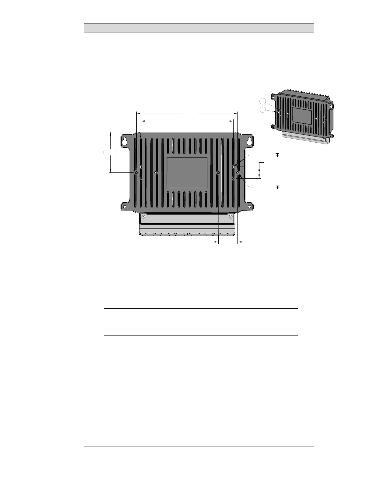
2.1 InstallationProcess
71.7
M4 x 0.7
178.4
6 mm min. (4x)
20 6 mm min. (4x)M3 x 0.5
34
163.2
D
C
The following is needed:
•A Phillips screwdriver for installation of the M12 protection bracket
•Four M5 × 0.8 screws conforming to the table above
•Installation tool for mounting screws
1. Unpack and check the delivery. If damage is found, notify the supplier.
Note:
Placetheoperatorpanelonastablesurfaceduringinstallation.
Droppingtheoperatorpanelorlettingitfallmaycausedamage.
2. Attach UL certified and approved cables to the operator panel. Approved
cables include:
–900-1616-01 cable TxBR-2 M12 female 4p to blank 3 meter (pwr) [EX]
–900-1618-01 cable TxBR-2 M12 male 4p to blank 3 meter (lan) [EX]
–900-1621-01 cable TxBR-2 M12 male 8p to blank 3 meter (com) [EX]
Other lengths may also be available; please contact Beijer Electronics for
details.
BeijerElectronics, MAEN276 11

Installation
3. DrillthecorrectholepatterninpaneloutlinedaboveorinstallunitonVESA
compliant mounting bracket.
–Connect cable A to the terminal, using 14-20 AWG (2.08–0.52 mm2),
180–220 N-cm torque.
Note:
Useminimum85°Ccopperconductorsonly.
12 BeijerElectronics, MAEN276
Installation
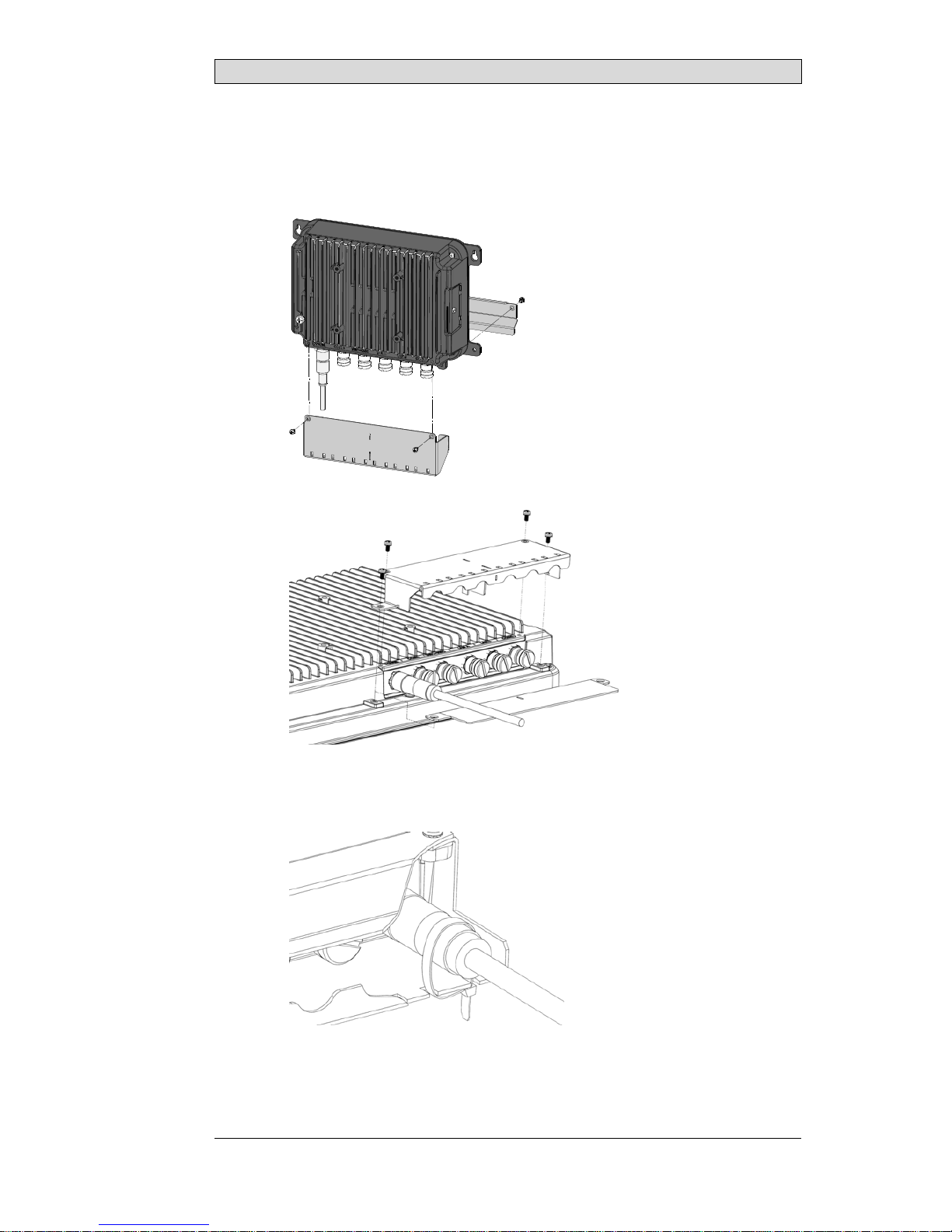
2.1.1 ProtectiveConnectorShield
InstallationProcess
1. Install the protective connector shield as shown.
2. Secure the cables to the protective connector shield using the included cable
ties
BeijerElectronics, MAEN276 13

Installation
Note:
Theprotectiveconnectorshieldisrequiredtobeusedonallapplications.
2.1.2 ConnectionstotheController
For information about the cables to be used when connecting the operator panel to
the controller, please refer to the help file for the driver in question.
2.1.3 OtherConnectionsandPeripherals
Cables, peripheral equipment and accessories must be suitable for the application
and its environment. For further details or recommendations, please refer to the
supplier.
14 BeijerElectronics, MAEN276
Technical Data
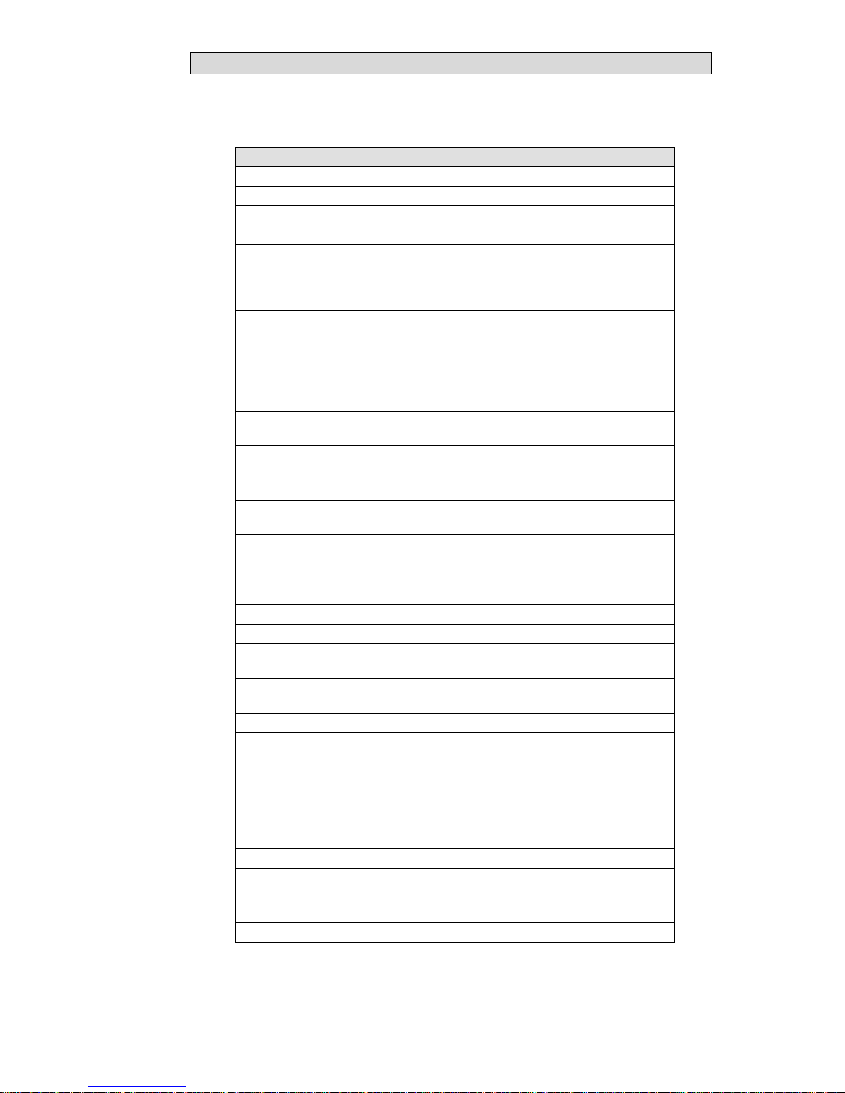
3TechnicalData
Parameter BoX2extreme
Dimensions,W×H×D 234×183×62mm
Sealing IP65
Framematerial Powder-coatedaluminum
Weight 1.5kg
CPU i.MX6Quad
QuadARMCortex-A9Core
1.0GHz
1MBL2cache
SerialportCOMA M12(8pin,male)
1×RS-232Rx/TxwithRTS(noCTS)and1×RS-422,or
2×RS-485or1×CAN2.0B
SerialportCOMB M12(8pin,female)
1×RS-485withisolated+5V/5mAoutforbiasresistor
network,or1×CAN2.0Bwithtermination
EthernetLANA M12(4Pin,female,D-codedaccordingtoEN/IEC
61076-2-101)10/100MbitviaRMII
EthernetLANB M12(4Pin,female,D-codedaccordingtoEN/IEC
61076-2-101)10/100MbitviaRMII
USB SupportsuptoUSB2.0HighSpeed
Externalstorage
media 1×SDcard
Flashmemory
(application
memory)
3.5GBSSD(eMMC)
MemoryRAM 2GBDDR3
NVRAM 64kB
Realtimeclock Yes
Battery BR2477A/GANlithiumbattery,
nonreplaceable
Powerconsumption
atratedvoltage 8W
Fuse InternalDCfuse,4ATSMT
Powersupply +24VDC
CE:Thepowersupplymustconformwiththerequirements
accordingtoEN/IEC60950andEN/IEC61558-2-4.
ULandcUL:Thepowersupplymustconformwiththe
requirementsforclass2powersupplies.
Operating
temperature -30°Cto+70°C
Storagetemperature -40°Cto+80°C
Relativehumidityin
operation 5%–95%non-condensation
Vibration 4g,accordingtoEN/IEC60068-2-6,TestFc
Mechanicalshock 40g,half-sine,11msaccordingtoEN/IEC60068-2-27
BeijerElectronics, MAEN276 15

Technical Data
Parameter BoX2extreme
Approvalsand
certifications CE/FCC/KC
Informationisavailableonwww.beijerelectronics.com
ULapproval Informationisavailableonwww.beijerelectronics.com
Marinecertificates Informationisavailableonwww.beijerelectronics.com
16 BeijerElectronics, MAEN276

Chemical Resistance
4 ChemicalResistance
4.1 MetalCasing
The frame and casing material is powder-coated aluminum. This powder paint
withstands exposure to the following chemicals without visible change:
Aceticacid10% Phosphoricacid4%
Citricacid10% Phosphoricacid10%
Diesel Seawater
Distilledwater Sodiumchloride2%
Edibleoil Sodiumchloride20%
Fueloil Sulphuricacid20%
Hydrogenperoxide3% Tapwater
The powder paint shows limited resistance to the following chemicals at room
temperature:
Butanol Nitricacid3%
Hydrochloricacid5% Nitricacid10%
Isopropylalcohol Phosphoricacid43%
Sodiumhypochlorite10% Turpentine
Note:
Ifexposuretoanyoftheabovechemicalsisdemanded,itisrecommendedtofirsttest
thechemicalinahiddenspotofthemetalcasing.
Thepowderpaintshowslittleornoresistancetothefollowingchemicalsatroom
temperature:
Aceticacid,conc. Methyl-ethylketone Toluene
Acetone Nitricacid30% Trichlorethylene
Ammonia5% Phenol Xylene
Ammonia,conc. Sodiumhydroxide5% 97octaneunleadedpetrol
Ethylacetate Sodiumhydroxide30% 98octaneleadedpetrol
BeijerElectronics, MAEN276 17

Chemical Resistance
18 BeijerElectronics, MAEN276

Operator Panel Drawings
5 OperatorPanelDrawings
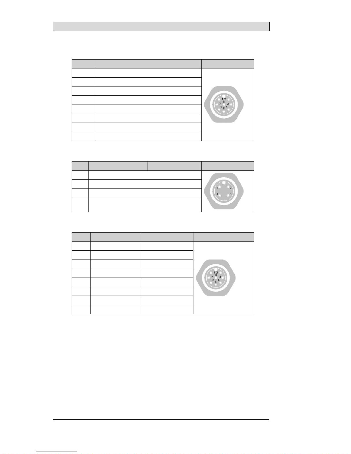
5.1 Connectors
123456
Pos Connector Description
1Powersupply +24VDC
2COMB Serialcommunicationport
3 USB1+USB2 USBHost2.0,maxoutputcurrent500mA
4 LANA 1×10/100Base-T
5 LANB 1×10/100Base-T
6COMA Serialcommunicationport
5.1.1 PowerSupply
Pin Description M12. 4pinmale
1V
in+
2V
in-
3V
in-
4V
in+
5.1.2 COMA
Pin COM1 COM2 COM3 M12,8pinmale
1RS422Tx+
RS485Tx+/Rx+ CAN-H
2 RS232_RxD - -
3 RS232_TxD - -
4 RS422_Rx+ -
5GND GND -
6RS422Tx-
RS485Tx-/Rx- CAN-L
7 RS232_RTS - -
8 RS422_Rx- -
BeijerElectronics, MAEN276 19
Operator Panel Drawings
5.1.3 USB1/2
Pin USB1/2 M12,8pinmale
1V
cc
2USB2D-
3USB2D+
4GND
5V
cc
6USB1D-
7USB1D+
8GND
5.1.4 LANA/LANB
Pin LANA LANB M12,4pinmale
1Tx+
2Rx+
3Tx-
4Rx-
5.1.5 COMB
Pin COM3 CAN M12,8pinmale
1 RS-485Tx+/Rx+ CAN-H
2 TERM+ TERM+
3- -
4- -
5GND GND
6 RS-485Tx-/Rx- CAN-L
7 TERM- TERM-
8V
cc Vcc
20 BeijerElectronics, MAEN276
Other manuals for BoX2 extreme
2
Table of contents
Other Beijer Electronics Gateway manuals

Beijer Electronics
Beijer Electronics GN-9372 User manual

Beijer Electronics
Beijer Electronics G Series Installation manual

Beijer Electronics
Beijer Electronics Korenix JetWave 4110L User manual

Beijer Electronics
Beijer Electronics X2 extreme 15 SL HP User manual

Beijer Electronics
Beijer Electronics Korenix JetWave 4110L User manual

Beijer Electronics
Beijer Electronics Korenix JetWave 2310 Series User manual

Beijer Electronics
Beijer Electronics korenix JetWave 3220v3 Series User manual


 manual")