fisair DFLEX Series Use and maintenance manual

FISAIR S.L. C/Uranio, 20; PoI. Ind. Aimayr, 28330 San Martín de la Vega (Madrid) España.
Tel: (+34) 91 692 15 14 Fax: (+34) 91 691 64 56 | info@fisair.com| fisair.com
HANDLING AND CONTROL MANUAL
DFLEX SERIES
MMCSX-EN-21-1
In compliance with the European Union regulations on the Safety of Machines,
you must read these instructions carefully before installing the equipment.

DFLEX Series Handling and Control Manual |
2

DFLEX Series Handling and Control Manual |
3
Contents
1. Introduction......................................................................................4
2. DFLEX operating instructions ............................................................5
3. Control panel and navigation keyboard of the PLC...............................7
3.1 Login and user levels................................................................................9
4. Modes of operation .........................................................................10
4.1 Manual mode........................................................................................10
4.2 Automatic mode....................................................................................10
4.3 Control of additional batteries..................................................................13
5. Initial state..................................................................................... 16
5.1 Configuration menu...............................................................................18
5.2 Adjustments menu.................................................................................23
6. Commissioning...............................................................................26
6.1 Manual mode selection ..........................................................................26
6.2 Automatic mode selection ......................................................................26
6.3 Shutdown .............................................................................................27
6.4 Emergency stop ....................................................................................27
6.5 PLC Inputs and outputs check................................................................28
7. Supervision menu........................................................................... 32
8. Information menu...........................................................................37
9. Alarms ...........................................................................................38
10. PLC List of alerts............................................................................. 40
11. Annex: Frequency inverter for the process fan motor.........................43

DFLEX Series Handling and Control Manual |
4
1. Introduction.
The FISAIR DFLEX series dehumidifiers have moving operating parts, such as two fan
motors (supply and reactivation) and a gear motor driving the desiccant wheel; and
variable static operating parts, such as air heaters/coolers, filters and flow control
devices.
The integration of the programmable logic controller S7-1200 in the dehumidifier
management and operational supervision provides faster, simpler, more accurate and
more reliable operation of the dehumidifier, while reducing electrical panel accessories.
The S7-1200 PLC controlling this type of equipment is a programmable device for the
configuration, setting and monitoring of the different equipment components connected
in real time. The equipment is operated from its own display or from a remote device.
The Electrical Diagram should be kept
along with this manual
The automatic program is designed so that the execution, actions and/or reactions
produced by the machine and its surroundings do not affect the level of safety and
functionality the machine is built for, while also observing the electromagnetic
compatibility directive.
Any removal and/or modification of the program contained in the PLC, operated from its
own display or an online PC, will modify the guarantee conditions, as well as compliance
with the directives and explicit rules covering its manufacture. The installer, handler or
user will then be responsible for the repercussions of the changed functionality of the
device.
The programmed device does not interfere with safety against personal injury; the
following examples of passive safety components are installed for this purpose:

DFLEX Series Handling and Control Manual |
5
2. DFLEX operating instructions
a) Flow control or motor fan process air pressure control.
b) Remote ON/OFF of fan motors.
c) Remote ON/OFF drive gear motor of the desiccant wheel.
d) Reactivation battery RB control. Regulating the reactivation battery RB controls
the equipment drying capacity (see user manual).
➢Manual mode, at 100% power.
➢Automatic mode:
•Configuration by "S" stages via two external digital signals.
•Proportional configuration “P” via a 0..10V DC analogue signal from an
external regulator.
•Configuration bymeasurment signal “M”. By means of a humidity probe
SH1 (0..10V DC).
e) Pre-heating battery control:
➢Via the temperature probe ST0 (0-10Vcc).
f) Pre-cooling battery control:
➢Via the temperature probe ST3 (0-10V DC).
g) Post-cooling battery and post-heating battery control:
➢Via the temperature probe ST2 (0-10V DC) or ST4 (0-10V)

DFLEX Series Handling and Control Manual |
6
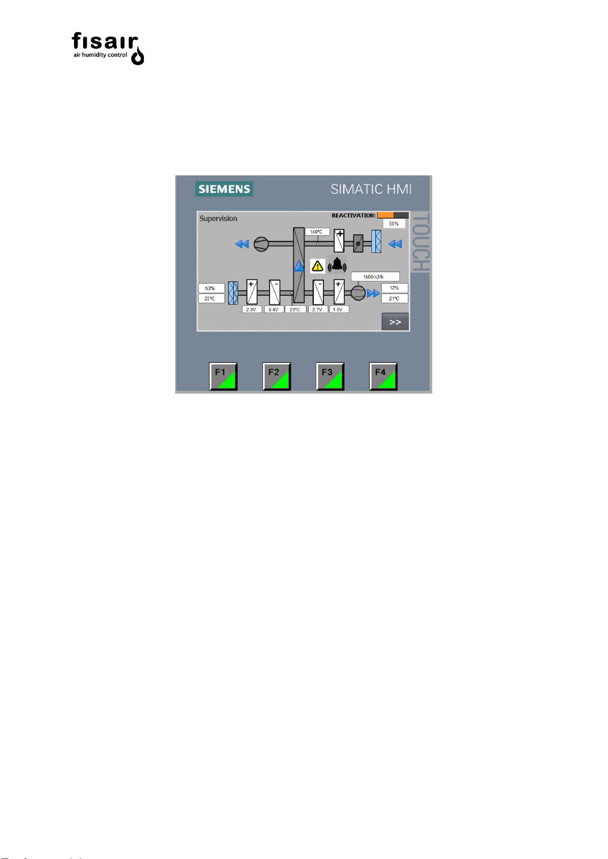
h) Measurement and supervision:
➢Temperature of the reactivation air measured by the probe (ST1).
➢Process air temperature measured by the probe (ST0) after the pre-heating
battery.
➢Process air temperature measured by the probe (ST3) after the pre-cooling
battery.
➢Process air temperature measured by the probe (ST4) after the post-
cooling battery.
➢Process air temperature measured by the probe (ST4) after the post-
heating battery.
➢Synopsis of component operation screen.
➢Monitoring the proportional modulation of the BR (power delivered by the
reactivation battery BR).
➢Monitoring the power delivered by the pre-heating battery.
➢Monitoring the power delivered by the pre-cooling battery.
➢Monitoring the power delivered by the post-cooling battery.
➢Monitoring the power delivered by the post-heating battery.
➢Humidity measurements (relative, absolute, dew point or mixing ratio) and
temperature measuredby the probe SH1-ST2 to be installed in the process
air inlet or return.
➢Humidity and temperature measurements by the probe SH2-ST4 to be
installed in the dry air supply.
➢Monitoring humidity set point.
➢Monitoring maximum humidity alarm set point.
➢Minimum reactivation air flow of and rotor rotation.
i) Safety and alarms:
➢Timing at the disconnection of the humid-air motor fan and the gearmotor
for cooling the equipment.
➢Alarm and equipment shutdown due to lack of air in the reactivation.
➢Alarm and equipment shutdown due to lack of rotation of the desiccant
rotor.
➢Alarm and equipment shutdown due to triggering any motor thermal cut-off.
➢Alarm and equipment shutdown due to triggering electrical protective
devices of the heaters.
➢Alarm and heater shutdown due to excessive SSR temperature.
➢Alarm for blocked process and reactivation filters (if applicable).
➢Alarm and BR heater shutdown due to excessive reactivation temperature
as measured by probe ST1.
➢Post heating heater shutdown due to excessive temperature as measured
by operating thermostat TF3. To be reset manually.

DFLEX Series Handling and Control Manual |
7
3. Control panel and navigation keyboard of the PLC.
I1. Break switch.
I2. MANual / 0 / AUTomatic selection switch
PLC. Programmable logic controller 4.3” projected resistive panel type touch screen with
the following functions:

DFLEX Series Handling and Control Manual |
8
The following screen shows the icons that can be pressed at any time while operating
the touch screen interface:
*For technical services.
DFLEX status
indication synoptic
Current
menu
Return to
the initial
menu
Next
screen
User
selection
Alarms
menu
Language
selection
Acess to
alarms
menú
Acces to
initial
menú
Acces to
supervision
menu
Exit from
“runtime” *

DFLEX Series Handling and Control Manual |
9
3.1 Login and user levels
Press the user selection to log in.
Session close time: All user levels have a session close time of 15 minutes. You will
need to log in again after these 15 minutes.
User levels
Login level***
Password***
Permission granted
No login
-
-
User
Electrical diagram no.*
Example:
Electrical diagram: E10776
Password: 00010776
•Access to fan regulation selection
by flow (Q) or pressure (P).
•Access to local or remote operation
mode configuration.
•Acces to Q/P set-point adjustment
•Access to H3 and Hx RH maximum
deviation Alarm set-point
adjustments.
•Acces to pre and post heating or
cooling batteries set-point
adjustments.
Technician
Configuration program
number**
Example:
Program PC20210468
Password: 00210468
In addition to the permissions of the
previous level:
•Access to modification of factor “K”
and “Qmax” in the fan regulation
selection
•Access to Tmax, Pmax and
Tunning.
Developer
For programmer.
•All the permissions of the previous
levels.
*Complete with 0 to the left up to 8 digits.
**Only the 6 numbers on the right.
***Case sensitive

DFLEX Series Handling and Control Manual |
10
4. Modes of operation
The unit can operate in two operating modes in which the reactivation battery RB power
output is managed differently.
The unit's drying capacity is controlled by managing the reactivation battery RB. (See
installation and maintenance manual)
There follows an explanation of the unit's operating modes:
4.1 Manual mode
If manual mode (MAN) is selected, the fan motors, speed reducer motor that turns the
rotor and the reactivation battery will start up immediately at 100% of their power output.
If the equipment has additional batteries, you must enter the required set points in the
settings menu for proper operation.
4.2 Automatic mode
In automatic mode (AUTO) the start-up of the fan motors and the speed reducer motor
depends on the H1 interlock and the operation of the reactivation battery is contingent
on the configuration of the control and interlock H2.
There are three control configuration types for the operational management of the
reactivation battery RB.
•Configuration by stages "S"
By means of two external digital signals, the reactivation battery is controlled with
two interlocks: H2 and H3. Each stage delivers an adjustable percentage of
power.

DFLEX Series Handling and Control Manual |
11
❖Functionalities of the Hn interlocks in configuration by stages "S".
-Interlock H1 (Terminals 14-15): ON/OFF remote ventilation and
rotor connection.
-Interlock H2 (Terminals 20-21): Connection of the RB first phase
Requires connection H1.
-Interlock H3 (Terminals 22-23) Connection of the RB second
phase.
•Proportional Configuration “P”:
By means of an external regulated analogue signal 0...10V DC from a humidity
controller/regulator a power output of 0...100% is obtained, supplied by the
reactivation battery RB.
This signal must be connected to the terminals 0A-A1. (See the associated
electrical diagram).
❖Functionalities of the Hn interlocks in proportional configuration "P".
-Interlock H1 (Terminals 14-15): ON/OFF remote ventilation and
rotor connection.
-Interlock H2 (Terminals 20-21): Reactivation battery ON/OFF
connection. Requires connection H1.
-Interlock H3 (Terminals 22-23) Not applicable in configuration "P".

DFLEX Series Handling and Control Manual |
12
•Configuration by Measurement signal "M":
Using the humidity probe SH1, the PLC regulates the power delivered by the
reactivation battery BR to reach the established set point.
The applicable humidity ranges for the probe to be connected are as follows:
-Relative humidity (RH): [0…100%] // [0…10V DC]
-Absolute humidity (Hx): [0…20g/kg] // [0…10V DC] (*)
-Dew point (Tdp): [-60…+40ºC] // [0…10V DC] (*)
The SH1 probe must be connected to the X1.18-1L+.terminals. (See the
associated electrical diagram).
The required humidity set point and the differential for the maximum permissible
humidity alarm are entered in the settings menu (AJUS) under HR/Hx(*)/Tdp(*).
The humidity alarm will be visible and will flash on the main screen when the
value measured by the SH1 probe is higher than the sumtotal of the setpoint and
the humidity alarm.
❖Functionalities of the Hn interlocks in proportional configuration "P".
-Interlock H1 (Terminals X1.14-15): ON/OFF remote ventilation
and rotor connection.
-Interlock H2 (Terminals X1.20-21): Reactivation battery RB
ON/OFF connection. Requires connection H1.
-Interlock H3 (Terminals X1.22-23) Not applicable in configuration
"M".
(*) Requires specific application

DFLEX Series Handling and Control Manual |
13
4.3 Control of additional batteries
The control of the additional batteries is independent of the selected working mode,
manual or automatic. At all times:
The control of the additional batteries is independent of the selected working mode,
manual or automatic.
•Anti-freeze pre-heating coil control: Electric battery
Using the ST0 temperature probe, the PLC energizes the pre-heating battery
heating elements (in all on/off regulation mode) to perform the antifreezefunction.
•Anti-freeze pre-heating coil control: Water battery
The openinng of the motor-valve actuator can be adjusted by reducing the limit
value of the analog output signal to reduce energy consumption depending on
the expected thermal jump compared to the outside air temperature.

DFLEX Series Handling and Control Manual |
14
•Pre-cooling battery control:
Using the temperature probe ST3, the PLC regulates the power delivered by the
pre-cooling battery to reach the set point.
The temperature probe must be connected to terminals regarding the associated
electrical diagram. As a general rule, the ST3 probe is installed in the BF1 and
connected according to factory settings.
The desired temperature set point is entered in the settings menu (AJUS) under
T3.
The temperature range of the probe to be connected must be [0ºC...+50ºC] //
[0...10V DC].

DFLEX Series Handling and Control Manual |
15
•Post-cooling battery and post-heating battery control:
Using the temperature probe ST4, the PLC regulates the power delivered by the
post-cooling battery and post-heating battery to reach the adjusted set point.
The combined probe SH2-ST4 must be installed in the dry air supply.
The desired temperature set point is entered in the settings menu (AJUS) under
T4.
The temperature range of the probe to be connected must be [0ºC...+50ºC] //
[0...10V DC].

DFLEX Series Handling and Control Manual |
16
5. Initial state
Having fulfilled the conditions for installation, checked that the network values match
those required for the machine and having made all of the electrical connections in
accordance with the control application:
Arm the switch (I1), and the following will appear on the control panel:
Initial state OK.
MAN -0- AUTO
Signalling card SEF-008
Remote signalling card
SEF-013
Initial state NOT OK.
The lower alarm button
flashes yellow to indicate an
alarm
MAN -0- AUTO
Signalling card SEF-008
Remote signalling card
SEF-013
On the signalling card SEF-008 lights up yellow, indicating that the unit is "live".
If there is any alarm/defect/fault in the unit, will also light up red, indicating
“warning”.
When the unit is switched on, lights up green, which indicates that the unit is
“running”.
WARNING!!! Do not switch on the unit without first reading sections 5.1 and 5.2.
Rx2
Rx3
Rx1
Rx1
Rx2
Rx3
MAN -0- AUTO

DFLEX Series Handling and Control Manual |
17
The unit has a remote signalling card SEF-013 with three relays (NC-NA) with which we
can obtain these remote status signals. This card is located inside the unit's electrical
board, in connection block X1.
Rx1. Remote relay indicating "unit is live"
Rx2. Remote relay indicating "running"
Rx3. Remote relay indicating "defect/alarm"
See the associated electrical diagram for its electrical connection.

DFLEX Series Handling and Control Manual |
18
5.1 Configuration menu
Operation mode configuration :
If you have chosen to operate in automatic mode, you must select from the configuration
menu one of the three pre-set configurations for operating the dehumidifier.
•Stages
•Proportional
•Measurement
For detailed information on the configuration, see section 4.2.
Selection of "S" stages configuration

DFLEX Series Handling and Control Manual |
19
Selection of "P" proportional configuration
Selection of configuration by measurement signal "M”

DFLEX Series Handling and Control Manual |
20
Fan control configuration
The default control mode is Flow, the air intakes of SQ1 being arranged for this type of
control. After following the steps in the User Manual (MUSX) to measure pressure, you
can change the control mode in this menu.
It should be noted that if you change the control mode, you must change the air intakes
of the SQ1 differential pressure transmitter. Refer to DFLEX Series User Manual section
9.9 for detailed explanation.
Access the following screen to select Q or P.
Pressing the key gives the following screen to select process fan control by flow
or pressure:
In the flow control option, the maximum process fan flow and the K factor value are set.
•Maximum Flow-10M1: The maximum flow limit [m3/h] allowed in the settings
menu is set.
•Factor K-10M1: The conversion factor K is set for the flow calculation according
to the process motor technical data sheet.
IMPORTANT: The user level is sufficient to select flow or pressure control and the
technician or developer level is required to configure Q max, maximum fan flow and
the factor K. See section 3.1 “Login and user levels”.
Other manuals for DFLEX Series
2
This manual suits for next models
8
Table of contents
Other fisair Dehumidifier manuals

fisair
fisair DFRA Series Use and maintenance manual

fisair
fisair DFRA Series User manual

fisair
fisair DFRB-060-E Installation guide

fisair
fisair DFRA Series Use and maintenance manual

fisair
fisair DFRIGO Series User manual

fisair
fisair DFRA Series User manual

fisair
fisair DFLEX Series User manual

fisair
fisair DFLEX Series User manual