FISHER HAMILTON SAFEAIRE series User manual

2
SAFEAIRE®LABORATORY FUME HOODS
OPERATION, MAINTENANCE AND INSTALLATION INSTRUCTIONS
GENERAL INFORMATION
Fisher Hamilton is pleased to have had the privilege of
furnishing your laboratory equipment. This is a major
investment, and your equipment is built to withstand extremes
of temperature, stress and corrosion provided you give it
reasonable care and use.
This manual gives you full information for the operation and
care of fume hoods and other Fisher Hamilton equipment
items.
Utility and fine appearance can be assured for many years by
following simple procedures. regular schedule of
maintenance will be most effective.
If you have a special problem or would like extra copies of this
manual, write to the Technical Service Department, Fisher
Hamilton, Two Rivers, Wisconsin 54241.
Table of Contents
GENERAL INFORMATION . . . . . . . . . . . . . . . . . . . . . . . . . . . . . 2–3
General . . . . . . . . . . . . . . . . . . . . . . . . . . . . . . . . . . . . . . . . . 2
Perchloric Acid Hoods . . . . . . . . . . . . . . . . . . . . . . . . . . . . . . 3
Hood Identi ication . . . . . . . . . . . . . . . . . . . . . . . . . . . . . . . . . 3
INSTALLATION . . . . . . . . . . . . . . . . . . . . . . . . . . . . . . . . . . . 4–19
Fume Hood Superstructures . . . . . . . . . . . . . . . . . . . . . . . . . . 4
Floor-Mounted Fume Hoods . . . . . . . . . . . . . . . . . . . . . . . . . 5–9
HOPEC IV Fume Hoods . . . . . . . . . . . . . . . . . . . . . . . . . . 10–11
Air Chamber, Auxiliary Air Fume Hoods . . . . . . . . . . . . . . . . . 11
Ba les . . . . . . . . . . . . . . . . . . . . . . . . . . . . . . . . . . . . . . 12–13
Sa ety Shields . . . . . . . . . . . . . . . . . . . . . . . . . . . . . . . . . 14–15
Blower Enclosures . . . . . . . . . . . . . . . . . . . . . . . . . . . . . 16–18
Fume Hood Monitors . . . . . . . . . . . . . . . . . . . . . . . . . . . . . . 19
Exhaust Filter Assembly . . . . . . . . . . . . . . . . . . . . . . . . . . . . 19
Minihelic Gauge . . . . . . . . . . . . . . . . . . . . . . . . . . . . . . . . . . 19
WARNING/OPERATING INSTRUCTIONS . . . . . . . . . . . . . . . . . . . . 20
MAINTENANCE AND ADJUSTMENTS . . . . . . . . . . . . . . . . . . 21–27
General Maintenance . . . . . . . . . . . . . . . . . . . . . . . . . . . . . . 21
Fume Hood Inspection . . . . . . . . . . . . . . . . . . . . . . . . . . . . . 21
How to Replace Fluorescent Light Tube . . . . . . . . . . . . . . . 21-22
Servicing Fume Hood Fixtures . . . . . . . . . . . . . . . . . . . . . . . . 22
Cleaning Fume Hood Interiors . . . . . . . . . . . . . . . . . . . . . . . . 22
Replacing Sash Glass and Cables . . . . . . . . . . . . . . . . . . 23–25
Servicing Supply Chamber Air Filter . . . . . . . . . . . . . . . . . . . . 26
Exhaust Filter Replacement . . . . . . . . . . . . . . . . . . . . . . . . . . 26
Blower RPM Adjustments . . . . . . . . . . . . . . . . . . . . . . . . . . . 27
Manometer, Monitoring Exhaust Filters . . . . . . . . . . . . . . . . . . 27
FIELD TESTING . . . . . . . . . . . . . . . . . . . . . . . . . . . . . . . . . . 28–30
TROUBLESHOOTING . . . . . . . . . . . . . . . . . . . . . . . . . . . . . . . . . 31
GENERAL
Fume hoods are exposed to extremes o temperature, reagent
umes and working sur ace abuse. Regular care will prolong
service li e and insure sa e working conditions.
The exhaust system and blower o a ume hood must unction
properly or sa ety. Maintenance personnel should service the
an and motor assembly regularly, lubricate as required, and
make sure that the exhaust system is ree rom obstructions.
Semiannually, accumulated deposits should be removed rom
the impeller blade and housing.
A simple test with lighted match or smoke will show i the air is
being drawn into the hood. More accurate checks o air velocity
can be made with a thermal anemometer. See Inspection and
Field Evaluation procedure.
Always place equipment and apparatus as ar back into the
ume hood as possible since this provides greater assurance o
proper ume collection and removal.
Large, bulky apparatus or equipment should be placed in the
ume hood to permit air low around it, and never placed so as
to inter ere with the operation o the ba le system. Raise large
items an inch or two above work sur ace. Spilled liquids, acids,
or corrosive materials should be immediately wiped up and the
sur ace neutralized with water or the proper neutralizing agent
so as to prevent damage to the work sur ace and the hood
interior or to apparatus and equipment installed in the hood.
Remember that special ume hoods are required or the
handling o Perchloric Acid. See next page.

SAFEAIRE®LABORATORY FUME HOODS
OPERATION, MAINTENANCE AND INSTALLATION INSTRUCTIONS
GENERAL INFORMATION
3
Dimensions are nominal and illustrations and speci ications are based
on the latest product in ormation available at the time o publication.
The right is reserved to make changes at any time without notice.
PERCHLORIC ACID HOODS
The properties o perchloric acid require that a specially
designed ume hood be set aside or exclusive use with this
material. The hood is equipped with a cold water spray device
or washdown o the interior sur aces. A trough is placed
across the back o the hood or collection and disposal o
washdown waters. Operating personnel should be well trained
in the proper handling techniques and be amiliar with the
characteristics o this material.
Frequency o washdown, both hood interior and exterior
system, is determined by the usage and concentration o
reagents. This can range rom a weekly procedure to one that
occurs a ter every use. Washdown should always be ollowed
by an inspection to veri y that all areas are clean and that the
wash system is unctioning properly.
Some o the hazards o perchloric acid which justi y the use o
a special hood are:
1. Perchloric acid is a very strong acid, capable o producing
severe burns when in contact with skin, eyes or respiratory
tract.
2. As an aqueous solution, it can cause violent explosions i
improperly handled.
3. It reacts with other substances to orm unstable materials
which are susceptible to exploding either by impact, riction,
or spontaneous combustion.
Persons using perchloric acid should be thoroughly amiliar with
its hazards. Many reported laboratory accidents have involved
less than one gram o reactant. Listed below are some common
sa ety practices that should be ollowed:
• Spilled perchloric acid should be thoroughly washed away
with large amounts o water.
• The use o organic chemicals or materials in the hood should
be avoided.
• Goggles or other e ective eye protection should be used
whenever possible, as well as utilization o the ume hood
sash or additional sa ety.
• Gas lames or oil baths should not be used within the hood.
• Organic chemicals should not be kept in storage areas set
aside or perchloric acid storage.
• A schedule should be made or regular washdown and
inspection o hood interior, ductwork and blower to guard
against a build-up o dangerous perchloric materials.
• Only a luorocarbon grease should be used as a blower
lubricant, since any other type is to be considered potentially
hazardous.
• Washdown procedure should be per ormed a ter completion
o usage with all apparatus removed rom hood.
HOOD IDENTIFICATION
Fisher Hamilton Inc Two Ri ers, WI 54241
Item/Room No. . . .
Item: 158C Room: 207
Job/Unit No. . . . . TX 394381 012 H012M Unit: 0005093
Product No. . . . . . FH3943810244 Entity:
Description . . . . . Desc: X54L836PD – DWG. HD01
Project Name . . . Project Name: RICE UNIVERSITY – OLD CHEMISTRY
Shop Order No. . . Shop Order #: 161914 P.O. No.: 22492/26108
Clr:
G1
G1
UNCRATED
Bar Code No. . . . . 018021957
Louver
Panel Side
Panel
2-Part Label
(Located
on backside
o collar and
inside o
louver panel)
Gasketed
Access
Panel
Liner
Sash Ba les
TX 394381 FH3943810244
X54L836PD – DWG. HD01
Placed on backside o collar
Placed on inside
o louver panel

4
Dimensions are nominal and illustrations and speci ications are based
on the latest product in ormation available at the time o publication.
The right is reserved to make changes at any time without notice.
SAFEAIRE®LABORATORY FUME HOODS
OPERATION, MAINTENANCE AND INSTALLATION INSTRUCTIONS
INSTALLATION
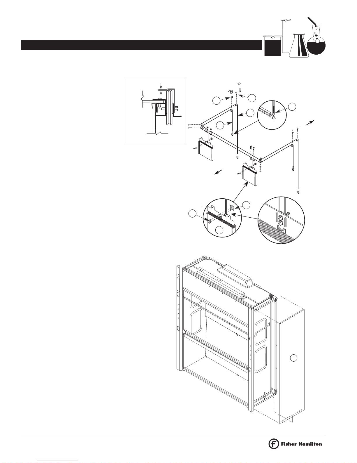
FUME HOOD SUPERSTRUCTURE INSTALLATION
Side Enclosure Panels
1. Lower the side panel into the side rame o the ume hood
superstructure, engaging the rame’s lower lip. While
pressing down on the two black catches, rotate the side
panel and engage the rame’s upper lip. Gently apply
additional pressure to the panel and release the catches to
secure the panel to the hood.
Shipping
Screws
Weight
Pan
Work Sur ace
Top o
Fume Hood
Shipping
Screw
Louver
Panel
No. 10 X 5/8"
Screws
2. Remove two (2) shipping screws that secure the counter-
balance weight pan to the rear top rail.
3. Remove screws rom sash hold-down clips. Open the sash
and remove blocking, being care ul not to damage sill or
ba les.
NOTE: Ba les can be installed at this time, or a ter the hood is
in place on the work sur ace. See Pages 12–13.
8. Drill two (2) each 1/8" diameter pilot holes at each side
structural rame into the work sur ace and secure same
with our (4) No. 10 X 5/8" screws saved rom the
shipping skid.
9. Reinstall end panels.
10. Caulk hood to work sur ace with silicone sealant.
6. Remove two (2) shipping screws rom the top o the louver
panel. These screws must be remo ed to allow future
access to the fluorescent lights.
7. Check the ollowing items:
• That the counterweight operates ree o obstructions.
• That the cables align properly in the pulleys.
• That there is proper horizontal sash alignment and
counterweight balance.
• That the sash does not bind in the sash guides.
4. Remove shipping screws holding the ume hood rame to
the skid. Save our (4) o these screws, No. 10 X 5/8", to
secure hood to the work sur ace.
5. Place the ume hood on the work sur ace taking care to
protect the work sur ace.
Catches
Side Panel
Lower Lip

SAFEAIRE®LABORATORY FUME HOODS
OPERATION, MAINTENANCE AND INSTALLATION INSTRUCTIONS
INSTALLATION
5
Dimensions are nominal and illustrations and speci ications are based
on the latest product in ormation available at the time o publication.
The right is reserved to make changes at any time without notice.
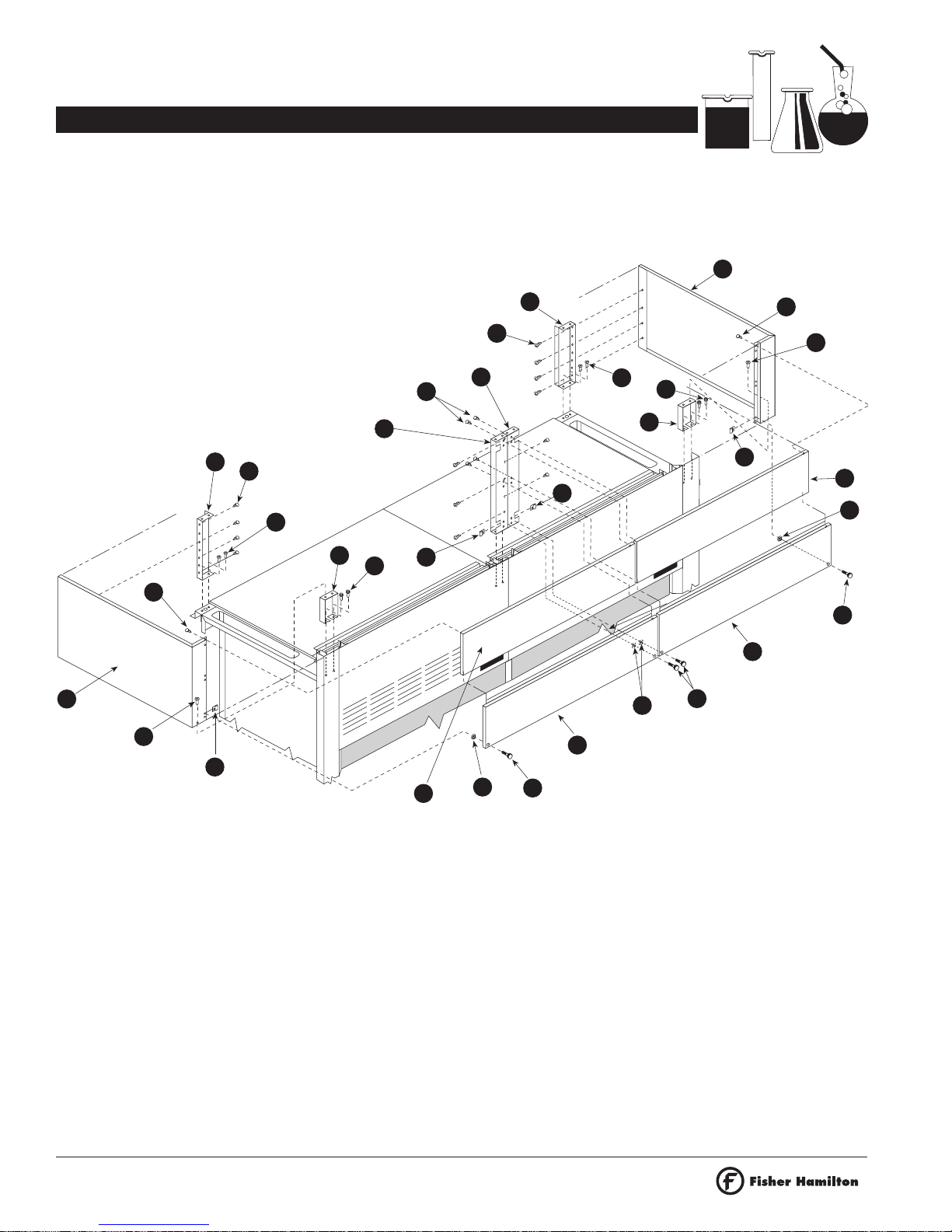
1. Attach le t-hand side assembly (2) to back assembly (1).
Take back panel assembly and stand vertically, as shown,
and slide into end assembly. (Angle lange o end assembly
its between back panel and horizontal members o back
assembly). Secure each corner with two #8 X 5/8" PPHSMS
at mating holes on top and bottom corners o joined
assembly. Repeat steps with right-hand end (3). Attach each
ba le support with two each #8 X 3/4" PPHTCS through
back panel into support. Do not over-tighten.
#8 X3/4" PPHTCS
#8 X5/8" PPHSMS
1
2
1
2
ASSEMBLY INSTRUCTIONS FOR KNOCKED-DOWN
FLOOR-MOUNTED FUME HOODS
General - When receiving ume hood assemblies, inspect or
damage immediately. I damage is noted, request the delivering
carrier to note and describe damage on bill o lading prior to
your signature. Noti y carrier immediately and request
inspection.
Open boxes and crates and examine or hidden damage. I
damage is noted, save containers and request an inspection.
Move all components to installation area.
2. Attach top assembly (4), as shown at le t, to
back and ends with eleven (11) #10 X 5/8"
PPHSMS. Top assembly its underneath right-
hand rear pulley bracket assembly. Secure
exhaust collar to rear rail.
#10 X5/8" PPHSMS
2
TOP
BACK REAR PULLEY
BRACKET ASSEMBLY

6
Dimensions are nominal and illustrations and speci ications are based
on the latest product in ormation available at the time o publication.
The right is reserved to make changes at any time without notice.
SAFEAIRE®LABORATORY FUME HOODS
OPERATION, MAINTENANCE AND INSTALLATION INSTRUCTIONS
INSTALLATION
5
3. Attach le t rear pulley assembly (5) using three (3) #8 X 5/8"
PPHSMS. Attach right rear plate assembly (6) using three (3)
#8 X 5/8" PPHSMS. Slide 3" sheave (7), then 2" sheave (8)
over threaded stud. Loosely asten with 1/4-20 KEPS nut.
Install right-hand cable retainer support (27) using two (2)
#8 X 5/8" PPHSMS.
27
8
7
6
ASSEMBLY INSTRUCTIONS FOR KNOCKED-DOWN FLOOR-MOUNTED FUME HOODS
#8 X5/8" PPHSMS
9
4. Remove pieces o tape (9) holding top panel extrusion in
place. Li t header panel (11) and place bottom in right-hand
and le t-hand ba le clips (10). (Short header panel - bypass
hoods, does not have ba le clips). Bottom extrusion on
header panel aces outward. Fasten top o header panel to
angle with #8 X 5/8" PPHSMS.
10
11

SAFEAIRE®LABORATORY FUME HOODS
OPERATION, MAINTENANCE AND INSTALLATION INSTRUCTIONS
INSTALLATION
7
Dimensions are nominal and illustrations and speci ications are based
on the latest product in ormation available at the time o publication.
The right is reserved to make changes at any time without notice.
5. Install our (4) ba les as indicated.
Install ba les with notches down.
Proceed rom bottom to upper ba le
(12, 13, 14, 15). I remote control is
included with hood, place
intermediate ba le (14) in already
installed remote control ba le arm
(16). Lower and intermediate ba les
are the same size. Insert upper ba le
into collar extrusion per Detail “B”.
Test remote control ba le adjuster or
unction. 16
15
14
13
12
COLLAR
TOP PANEL
UPPER
BAFFLE
DETAIL “B”
INTER-
MEDIATE
BAFFLE
LOWER
BAFFLE
BOTTOM
BAFFLE
UPPER
BAFFLE
ASSEMBLY INSTRUCTIONS FOR KNOCKED-DOWN FLOOR-MOUNTED FUME HOODS
6. Install rear top sash (17) in right-hand and le t-hand rear
sash guides. Sashes are installed rom the top o the hood.
Lower the sashes into the sash guides. The rear top sash
must be located above the stops located approximately hal
way up the sash guides. Locate the ront bottom sash (18) in
the ront right-hand and le t-hand sash guide. Remove the
tape rom the cable assemblies that are taped to each sash.
Uncoil the cable and place on top o hood.
17
REAR TOP
18
FRONT BOTTOM
8
Dimensions are nominal and illustrations and speci ications are based
on the latest product in ormation available at the time o publication.
The right is reserved to make changes at any time without notice.
SAFEAIRE®LABORATORY FUME HOODS
OPERATION, MAINTENANCE AND INSTALLATION INSTRUCTIONS
INSTALLATION
7. Be ore hood is pushed against wall, place top rear sash
cable (19) over pulleys as shown in instructions. Brace
bottom o sash about 6" above sash stops, with 2 x 4 or
similar, to allow or a more manageable cable. Attach weight
(20) to cable, Detail “C”. Fasten cable clamp (23) and two
(2) 1/4-20 X 3/4 HHTCS (24), do not completely tighten
screws. Repeat process with ront bottom sash cable (21).
Test sash level, alignment and travel. Make any necessary
adjustment. I necessary, ine tune weight pan. Fasten clamp
screws tightly. Attach all cable retainers (22, 25). Do not
over-tighten retainers – allow 1/16" or pulley movement. See
Detail “D”. The nylon tape (26) at the cable loops at the ends
o the sash pull is no longer necessary, remove and discard.
25
Retainer Must
Not Touch
Sheave
0.062"
DETAIL “D”
22
21
19
26
BOTTOM
FRONT
REAR
TOP
23
20
24
BACK
OF
HOOD
FRONT
OF
HOOD
ASSEMBLY INSTRUCTIONS FOR KNOCKED-DOWN FLOOR-MOUNTED FUME HOODS
8. Position ume hood in a permanent location. Have quali ied
personnel attach all required electrical devices and plumbing
ixtures. Lower the side panel (27) onto the side rame o the
ume hood, engaging the rame’s lower lip. While pressing
down on the two black catches, rotate the side panel and
engage the rame’s upper lip. Gently apply additional
pressure to the panel and release the catches to secure the
panel to the hood.
27

28
SAFEAIRE®LABORATORY FUME HOODS
OPERATION, MAINTENANCE AND INSTALLATION INSTRUCTIONS
INSTALLATION
9
Dimensions are nominal and illustrations and speci ications are based
on the latest product in ormation available at the time o publication.
The right is reserved to make changes at any time without notice.
9. Attach lintel panel (28) to ront o hood. Engage top o
panel with studs on top, inside o ront access panel and
asten bottom o panel to angles on ront access panel with
#8 X 5/8" PPHSMS. Drive screws as shown.
10. Make sure hood is square and aligned.
#8 X5/8" PPHSMS
ASSEMBLY INSTRUCTIONS FOR KNOCKED-DOWN FLOOR-MOUNTED FUME HOODS

10
Dimensions are nominal and illustrations and speci ications are based
on the latest product in ormation available at the time o publication.
The right is reserved to make changes at any time without notice.
SAFEAIRE®LABORATORY FUME HOODS
OPERATION, MAINTENANCE AND INSTALLATION INSTRUCTIONS
INSTALLATION
HOPEC IV FUME HOOD INSTALLATION
1. Install and level two ume hood base cabinets with rear
illers and kneespace panel as required.
2. Depending on height requirements, install either the top iller
rame assembly alone or in combination with the optional-
height iller rame.
HOPEC IV Hood
Base
Cabinet
Trough
Assembly
Run silicone
sealant bead
on back lange o
trough. Place work
sur ace into rame
and onto trough
lange.
I the TOP FILLER FRAME ONLY IS
REQUIRED, insert rough assembly into top
iller rame and locate ront lower edge o
trough lush with cabinet or optional height
iller. Secure to the base cabinet using
eight (8) No. 10 X 5/8" PPHSMS through
the side returns o the Top Filler Frame into
the ront and rear returns o the base
cabinet.
I the OPTIONAL HEIGHT FILLER FRAME
IS REQUIRED, it is installed by aligning
it’s bottom 3/4" return on the base
cabinet and securing with (4) No. 10 X
5/8" PPHSMS screws. Insert through
assembly into Top Filler Frame and locate
ront lower edge o trough lush with
cabinet or optional height iller. Attach the
Top Filler Frame to the Optional Filler
Frame using eight (8) No. 10 X 5/8"
PPHSMS through the side returns o the
Top Filler Frame into the ront and rear
returns o the base cabinet.
36"
Work Sur ace
Height
Top Filler Frame
Optional Filler
Filler
End view showing HOPEC IV hood,
Top Filler Frame and Base Cabinet.
Optional
Height Filler
Top Filler
Frame
Work
Sur ace
Base
Cabinet
HOPEC IV Hood
Base
Cabinet
36"
Work Sur ace
Height
Top Filler Frame
Filler
End view showing HOPEC IV hood,
Top Filler Frame, Optional Height
Filler and Base Cabinet.
Trough
Assembly
Run silicone
sealant bead
on back lange o
trough. Place work
sur ace into rame
and onto trough
lange.
Lower ront
edge o trough
should be lush
with ront o
cabinet
Top Filler
Frame
Work
Sur ace
Base
Cabinet

SAFEAIRE®LABORATORY FUME HOODS
OPERATION, MAINTENANCE AND INSTALLATION INSTRUCTIONS
INSTALLATION
11
Dimensions are nominal and illustrations and speci ications are based
on the latest product in ormation available at the time o publication.
The right is reserved to make changes at any time without notice.
HOPEC IV FUME HOOD INSTALLATION (cont..)
Base
Cabinet
INSTALLING AIR CHAMBER – AUXILIARY AIR
FUME HOODS
Upper
Screws
Filler
Screws
3. Set the ume hood trough onto the top iller rame. The rear
edge o the trough will set over the ront horizontal rail and
the return edge on the trough will secure it in place.
NOTE: I a drain tube is required, it should be installed at
this time. The tube is located at the le t end o the trough
and is ed through the top o the le t hand base cabinet into
a one gallon container.
4. Install poly vent, i required, through pre-drilled holes in the
backs o base cabinets. The tail piece o the vent is supplied
with a double compression assembly to lock it in place.
5. Seal the top edge o the trough assembly with a RTV silicon
or other applicable sealer and then place the ume hood
work sur ace into the Top Filler Frame. I base cabinet poly
vents are used, align them to the pre-cut holes in the work
sur ace.
6. Install cupsinks i required. The ume hood base cabinets are
supplied with pre-punched holes in the back panels above
the stone liner or cupsink drains. Cupsink assemblies are
supplied with the sink, an extension pipe, an elbow, and a
pipe section that protrudes through the hole in the base
cabinet back. The cupsink assembly is designed to it two
conditions.
A. When the ume hood assembly is supplied with the
Optional Height Filler Frame, the cupsink assembly is
ished through the sink cutout hole in the work sur ace
and the drain line hole at the rear o the base cabinet.
B. When the ume hood is supplied with only the Top Filler
Frame, the extension pipe below the cupsink is removed
to maintain alignment with the base cabinet rear drain
hole. The pipe extension should be saved in the event
that the Optional Height Filler Frame be required at a later
date.
7. Move the HOPEC IV ume hood to the area o installation.
Per orm Steps 1–10 on Page 4.
Top Filler
Frame
Work Sur ace
Front
Horizontal Rail
Trough
Drain Tube
Must Be Flush
Keyhole Slots
Lower Screws
4. Install the le t- and right-hand illers along with two (2)
screws each side, accessible rom inside the air chamber.
Front
Access
Post Screws
5. Install louver panel by hooking top edge onto studs in
chamber. Secure with three (3) screws.
6. Install sash enclosure by hooking top rame lange onto
o set angle on back o air chamber.
Stud
1. With hood on work sur ace, lower air make-up tubing to
expose our (4) mounting holes in galvanized rame. Install
screws into upper mounting holes, tightening hal way.
2. Li t the air chamber up and onto the upper mounting screws.
Two people are required or this procedure, one at each end
o the chamber. While chamber is supported by the upper
screws, install the lower mounting screws. Tighten all
mounting screws securely.
3. Li t make-up air tubing back up and into PVC elbows at ends
o air chamber. Secure with screws provided with elbows.
12
Dimensions are nominal and illustrations and speci ications are based
on the latest product in ormation available at the time o publication.
The right is reserved to make changes at any time without notice.
SAFEAIRE®LABORATORY FUME HOODS
OPERATION, MAINTENANCE AND INSTALLATION INSTRUCTIONS
INSTALLATION
BAFFLE INSTALLATION AND ADJUSTMENT
Fisher Hamilton provides two choices o ba le design
concepts:
1. Multi-position ixed.
2. Remote exterior control
Baffle Installation
Install ba les according to in ormation on the next page.
See label located on interior right-hand wall or repositioning
instructions or Multi-Position Fixed Ba le. See label located
on right ront post or Remote Exterior Ba le adjustment
instructions.
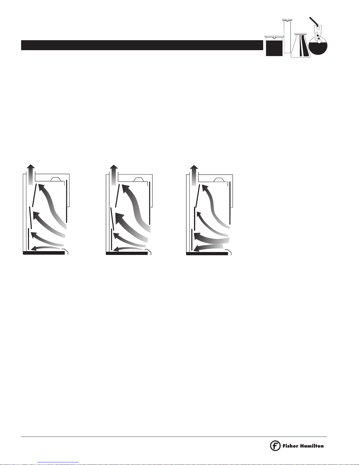
Baffle Adjustment
Fisher Hamilton ume hoods have three ba le settings:
A. Normal or Average.
B. Lighter-than-Air or high thermal loading.
C. Heavier-Than-Air
Position Ais or normal exhaust requirements. Locate ba le in
center o movement arc. All slots are unctional. This ba le
position is suitable or most ume generating activities.
Ba le position Bis or lighter-than-air gases, or high heat
loads. The top slot is open to maximum. The upper portion o
perimeter slot is operational. The intermediate horizontal slot is
operational and bottom slot is restricted. Fume hood air low is
concentrated in the upper portion o enclosure or e icient
capture and exhaust o lighter-than-air umes and hot gases.
The ba le at position Cprovides maximum air low across the
work sur ace or the collection and removal o umes generated
at the work sur ace and heavier-than-air gases. In this position,
perimeter slot and intermediate slot remain open and
operational, top slot is closed.
A – Normal Exhaust
Requirements B – High Heat Loads or
Lighter-Than-Air Gases
C – Hea ier-Than-Air Gases
and Surface Fumes

SAFEAIRE®LABORATORY FUME HOODS
OPERATION, MAINTENANCE AND INSTALLATION INSTRUCTIONS
INSTALLATION
13
Dimensions are nominal and illustrations and speci ications are based
on the latest product in ormation available at the time o publication.
The right is reserved to make changes at any time without notice.
BAFFLE INSTALLATION AND ADJUSTMENT (cont..)
Installing Multi-Position Fixed Baffle
1. Place top ba le into position by engaging top edge into
ront exhaust collar extrusion. Li t ba le up and into upper
support brackets to lock into position.
2. Place center ba le into desired exhaust position by engaging
top edge into appropriate slots on bottom o uppermost
ba le support brackets, see positioning label on right-hand
side panel. Li t and lock ba le into position.
3. Place lower ba le into proper position. Li t and lock ba le
into lower support brackets.
Installing Remote Exterior Control Baffle
1. Place top ba le into position by engaging top edge into
ront exhaust collar extrusion. Li t ba le up and into upper
support brackets to lock into position.
2. Align orked end o remote arm with any o three (3) slots in
right-hand upper ba le support bracket. Li t center ba le up
and into slots in upper ba le supports, being sure to capture
right-hand edge o ba le between ingers o remote control
arm. Li t and lock ba le into position.
3. Place lower ba le into proper position. Li t and lock ba le
into lower support brackets.
Exhaust Collar Extrusion
Top
Baffle
Center
Baffle
Lower
Baffle
Upper Support Bracket
Ba le Positioning Label
Lower Support Bracket
Top Baffle
Center Baffle
(Remote)
Center Baffle
(Fixed)
and Lower Baffle

14
Dimensions are nominal and illustrations and speci ications are based
on the latest product in ormation available at the time o publication.
The right is reserved to make changes at any time without notice.
SAFEAIRE®LABORATORY FUME HOODS
OPERATION, MAINTENANCE AND INSTALLATION INSTRUCTIONS
INSTALLATION
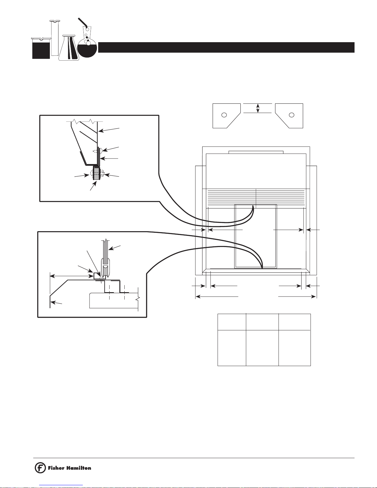
INSTALLING SAFETY SHIELDS IN RESTRICTED BYPASS, CONSTANT VOLUME BYPASS, AND RADIOISOTOPE
FUME HOODS
1. Locate lower track assembly according to dimensions
shown.
2. Use lower track assembly as template or locating holes.
Drill .128" diameter holes in sill as illustrated, through
existing holes in track assembly.
3. Fasten track with No. 8 X 3/8" PPHSMS.
4. Locate upper retainer on rear lange o louvered panel.
Locate retainer .91" (29/32") rom inside edge o ront
vertical panel. Drill .128" diameter holes using retainer as
template. Fasten with No. 8 X 3/8" PPHSMS.
5. Position and asten bumpers using No. 8-32 X 3/4" PPHMS,
washers and hex nuts.
6. Install sa ety shield by inserting top into upper retainer
channel, then lowering bottom (with rollers) into lower track
assembly.
Louvered Panel
8 X 3/8" PPHSMS
8 X 3/4" PPHSMS
Retainer
Bumper
Sa ety Shield
8 X 3/8" PPHSMS
Lower Track
Sill Work Sur ace
Lower Track
Upper
Retainer
.91"
1.87"
.91"
Hood Width
1.87"
Le t Bumper Right Bumper
.31"
Hood Lower Upper
Width Track Retainer
48.0" 34.62" 36.56"
60.0" 46.62" 48.56"
72.0" 58.62" 60.56"
96.0" 82.62" 84.56"
1.375"
SAFEAIRE®LABORATORY FUME HOODS
OPERATION, MAINTENANCE AND INSTALLATION INSTRUCTIONS
INSTALLATION
15
Dimensions are nominal and illustrations and speci ications are based
on the latest product in ormation available at the time o publication.
The right is reserved to make changes at any time without notice.
INSTALLING SAFETY SHIELDS IN AUXILIARY AIR FUME HOODS
1. Locate lower track assembly according to dimensions
shown.
2. Use lower track assembly as template or locating holes.
Drill .128" diameter holes in sill as illustrated, through
existing holes in track assembly.
3. Fasten track with No. 8 X 3/8" PPHSMS.
4. Locate upper retainer on rear lange o louvered panel.
Locate retainer .91" (29/32") rom inside edge o ront
vertical panel. Drill .128" diameter holes using retainer as
template. Fasten with No. 8 X 3/8" PPHSMS.
5. Position and asten bumpers using No. 8-32 X 3/4" PPHMS,
washers and hex nuts.
6. Install sa ety shield by inserting top into upper retainer
channel, then lowering bottom (with rollers) into lower track
assembly.
Louvered Panel
8 X 3/8" PPHSMS
8-32 X 3/4"
PPHMS and
Washer
Retainer
Bumper
Sa ety Shield
8 X 3/8" PPHSMS
Lower Track
Sill Work Sur ace
Lower Track
Upper
Retainer
.91" .91"
1.87"
Hood Width
1.87"
Le t Bumper Right Bumper
.31"
Hood Lower Upper
Width Track Retainer
48.0" 34.62" 36.56"
60.0" 46.62" 48.56"
72.0" 58.62" 60.56"
96.0" 82.62" 84.56"
3.56"
Nut & Washer

16
Dimensions are nominal and illustrations and speci ications are based
on the latest product in ormation available at the time o publication.
The right is reserved to make changes at any time without notice.
SAFEAIRE®LABORATORY FUME HOODS
OPERATION, MAINTENANCE AND INSTALLATION INSTRUCTIONS
INSTALLATION
INSTALLING CEILING ENCLOSURE TO FUME HOODS OTHER THAN AUXILIARY AIR AND POSTLESS SASH
Hardware included:
1 - Front panel
1 - Front panel-removable
2 - Side panels
2 - Front support brackets
2 - Rear support brackets
1 - Bag assembly
Tools required:
#2 Phillips screwdriver.
1. Fasten support brackets (1) in ront top o rame assembly in
holes provided. Use 1/4-20 X 3/4" hex head thread cutting
screws (HHTCS) (2) urnished in bag assembly to asten
brackets.
2. Fasten rear support (3) to rear top o rame assembly. Use
No. 8 X 5/8" Phillips pan head sheet metal screws (PPHSMS)
(4) urnished in bag assembly.
3. Install right-hand (5) and le t-hand (6) side panels to
supports using No. 8 X 5/8" PPHSMS (4).
4. Install ront panel (7) to side panels with No. 8 X 5/8"
PPHSMS.
5. Subassemble thumb screws (8) and push retainers (9) to
removable panel (10).
6. Insert hole asteners (11) in larger hole in lange o side
panels.
7. Insert top lange o removable panel under and behind ront
panel. Fasten thumb screws and tighten.
7
5
10
2
1
2
1
3
4
4
34
4
4
6
4
4
4
9
8
98
11
11

SAFEAIRE®LABORATORY FUME HOODS
OPERATION, MAINTENANCE AND INSTALLATION INSTRUCTIONS
INSTALLATION
17
Dimensions are nominal and illustrations and speci ications are based
on the latest product in ormation available at the time o publication.
The right is reserved to make changes at any time without notice.
INSTALLING CEILING ENCLOSURE TO AUXILIARY AIR FUME HOODS
Hardware included:
1 - Front panel-removable
2 - Side panels
2 - Front support brackets
2 - Rear support brackets
1 - Bag assembly
Tools required:
#2 Phillips screwdriver.
1. Fasten support brackets (1) in ront top o rame assembly in
holes provided. Use 1/4-20 X 3/4" hex head thread
cutting screws (HHTCS) (2) urnished in bag assembly to
asten brackets.
2. Fasten rear support (3) to rear top o rame assembly. Use
No. 8 X 5/8" Phillips pan head sheet metal screws
(PPHSMS) (4) urnished in bag assembly.
3. Install right-hand (5) and le t-hand (6) side panels to
supports using No. 8 X 5/8" PPHSMS (4).
4. Install clips (12) into top square holes o removable panel
(10).
5. Subassemble thumb screws (8) and push retainers (9) to
removable panel (10).
6. Insert hole asteners (11) in larger hole in lange o side
panel.
7. Insert clip o top lange o removable panel into square holes
o side panels. Fasten thumb screws and tighten.
5
10
2
1
2
1
3
4
4
34
4
4
6
4
9
8
98
11
11 12
12
18
Dimensions are nominal and illustrations and speci ications are based
on the latest product in ormation available at the time o publication.
The right is reserved to make changes at any time without notice.
SAFEAIRE®LABORATORY FUME HOODS
OPERATION, MAINTENANCE AND INSTALLATION INSTRUCTIONS
INSTALLATION
INSTALLING CEILING ENCLOSURE TO POSTLESS SASH TYPE FUME HOODS
Hardware included:
2 - Front panels
2 - Front panels-removable
2 - Side panels
2 - Front support brackets
2 - Rear support brackets
2 - Middle support brackets
1 - Bag assembly
Tools required:
#2 Phillips screwdriver.
1. Fasten support brackets (1) in ront top o rame assembly in
holes provided. Use 1/4-20 X 3/4" hex head thread
cutting screws (HHTCS) (2) urnished in bag assembly to
asten brackets.
2. Fasten rear support (3) to rear top o rame assembly. Use
No. 8 X 5/8" Phillips pan head sheet metal screws
(PPHSMS) (4) urnished in bag assembly.
3. Install right-hand (5) and le t-hand (6) side panels to
supports using No. 8 X 5/8" PPHSMS (4).
4. Install two middle supports (12) to louver panels with our
No. 8 X 5/8" PPHSMS (4).
5. Install ront panels (7) to side panels and middle supports
using No. 8 X 5/8" PPHSMS (4).
6. Subassemble thumb screws (8) and push retainers (9) to
removable panels (10).
7. Insert hole asteners (11) in larger hole in lange o side
panels.
8. Insert top lange o removable panels under and behind ront
panels. Fasten thumb screws and tighten.
5
10
2
1
2
1
3
4
4
34
4
4
6
4
9
8
98
11
11
12
4
12
4
7
7
4
10
98
11
11

SAFEAIRE®LABORATORY FUME HOODS
OPERATION, MAINTENANCE AND INSTALLATION INSTRUCTIONS
INSTALLATION
19
Dimensions are nominal and illustrations and speci ications are based
on the latest product in ormation available at the time o publication.
The right is reserved to make changes at any time without notice.
FUME HOOD MONITOR
Models 54L0335 and 54L0405
Proper ume hood operation is key to laboratory sa ety, com ort
and energy management. OSHA requires that laboratories take
measures to ensure proper and adequate operation o ume
hoods. Recommendations include the use o a continuous air
monitoring device. The ANSI Z9.5 and NFPA 45 standards
rein orce these requirements.
Fisher Hamilton monitors have the ability to monitor true ume
hood ace velocity using thermal sensors located in the
instrument. The thermal sensors are exposed to clean
laboratory air only. They can be sur ace-mounted in minutes
eliminating the need or expensive panel cutouts.
Each model is equipped with indicator lights that illuminate
based on a pre-determined set-point. An audible 85dB
piezoelectric alarm sounds and a red indicator light illuminates
to warn o potentially dangerous low air low conditions.
•54L0405
– Low low set point
– Audible and visual alarm
– I/O options
•54L0335
– Analog meter
– Audible and visual alarm
– I/O control
Fisher Hamilton ume hood monitors are shipped with operation
manuals
EXHAUST FILTER INSTALLATION
Product Numbers 54L296, 54L297, 54L298 and
54L299
The pre- ilter cover aces
forward on Restricted
Bypass and Constant
Volume Bypass hoods.
INSTALLATION OF MINIHELIC GAUGE
Replacement ilter sets consist o one rough and one HEPA
ilter.
Product Number 54L302 – Filter set or 54L296 or 54L298.
Product Number 54L300 – Filter set or 54L297 or 54L299.
Pre-Filter
Cover
Front o
Fume Hood
The pre- ilter cover aces to
the left on Auxiliary Air
hoods.
Pre-Filter
Cover
Front o
Fume Hood
Securely attach the ilter inlet collar to hood exhaust transition
using same method as ollowed in the duct system. Filter outlet
may be attached to duct using lexible connector or same as
inlet connection.
Sensor block and sensor tube,
two req’d each
Connect to low side o
Minihelic Gauge
Thick-wall vinyl laboratory
tubing, cut to length
Minihelic Gauge range 0"-3"
W.C., reads ilter pressure drop
Front Post
Connect to
high side o
Minihelic Gauge

20
Dimensions are nominal and illustrations and speci ications are based
on the latest product in ormation available at the time o publication.
The right is reserved to make changes at any time without notice.
SAFEAIRE®LABORATORY FUME HOODS
OPERATION, MAINTENANCE AND INSTALLATION INSTRUCTIONS
WARNING/OPERATING INSTRUCTIONS
WARNING/OPERATING INSTRUCTIONS
Re er to Operation
Instructions on le t-hand
ront post. Data rom the
“As Manu actured” test
should be logged in this
area along with any
urther Field Test results.
(See Page 28 and 29)
WARNING
This product is intended or use with certain chemicals that
can cause serious injury or illness through inhalation or
physical contact. While this product is intended to minimize
exposure to certain hazardous chemicals when selected,
installed and operated properly, its per ormance and the sa ety
o the user is a ected by a number o actors. These include the
HVAC
system, the speci ic chemicals and processes being used,
proper operation and the condition o the room.
Be ore using this ume hood, consult the owner’s industrial
hygienist or sa ety representative to make sure: 1) the speci ic
ume hood alarms, controls and the HVAC system have been
properly selected and are operating correctly, 2) the hood has
been tested a ter installation and routinely therea ter to ensure
the ume hood is providing the proper containment or the
speci ic chemicals and processes being used, 3) there has
been appropriate training on the correct use o the ume hood
and handling o the speci ic chemicals and the ume hood
operating instructions have been reviewed, 4) any personal
protective devices that are required are properly selected and
provided, and 5) the ume hood is being operated at the
appropriate ace velocity. The ume hood should never be
operated with the sash in the ull open position.
OPERATING INSTRUCTIONS
Failure to follow these instructions could result in physical
injury or illness.
Caution: Do not use hood for perchloric acid procedures.
1. Do not use this ume hood unless you have received proper
training rom the owner’s industrial hygienist or sa ety
representative.
2. This ume hood is not intended to be used with all chemicals
or all chemical processes. Consult the owner’s industrial
hygienist or sa ety representative to determine whether the
hood is appropriate or the chemicals and processes to be
used.
3. Veri y that the ume hood exhaust system and controls are
operating properly and providing the necessary air low. I in
doubt, the owner’s industrial hygienist or sa ety
representative should be consulted. It is recommended that
the hood be equipped with an air low monitoring device.
Be ore using the ume hood, veri y that the monitor is
operating properly by testing the monitor.
4. The hood should not be operated with the sash in the ull
open (set-up) position. When the hood is in use, the opening
o the sash glass should be kept at a minimum. On a
vertical rising sash, the sash glass should be no higher than
18". Horizontal sliding panels on combination sashes must
be closed when sash is raised vertically. The sash should
remain closed when the hood is not in use.
5. Place chemicals and other work materials at least six (6)
inches inside the sash.
6. Do not restrict air low inside the hood. Do not put large
items in ront o the ba les. Large apparatus should be
elevated on blocks. Remove all materials not needed or the
immediate work. The hood must not be used or storage
purposes.
7. Never place your head inside the hood.
8. External air movement can a ect the per ormance o the
hood. Do not operate near open doors, open windows or
ans. Avoid rapid body movements. Do not open the hood i
there are cross-dra ts
or turbulence in ront o the hood. Do not open the sash
rapidly.
9. I this hood is equipped with adjustable ba les, do not
adjust the ba les without consulting the owner’s industrial
hygienist or sa ety representative.
10. Wear gloves and other protective clothing i contact with
contaminants is a hazard.
11. Clean spills immediately.
12. I umes or odors are present, stop operating the hood,
close the sash and contact the owner’s industrial hygienist
or sa ety representative immediately.
13. It is recommended that this ume hood be tested and
certi ied annually by the owner according to applicable
industry and government standards.
Table of contents
Popular Laboratory Equipment manuals by other brands


Helmer Scientific
Helmer Scientific i.Series Service and maintenance manual

Civco
Civco GUS G32-S Operator's manual

Gema
Gema OptiFlow IG07 Operating instructions and spare parts list

Kinematics
Kinematics 4400/PVC operating instructions

Scilogex
Scilogex SCI550-H user manual

Hydac
Hydac OFX Operating and maintenance instructions

Thermo Scientific
Thermo Scientific Heraeus Multifuge X1 Instructions for use

Markes International
Markes International HiSorb Agitator U-HSAG-20 Instructions for use

HF Scientific
HF Scientific M100+ 28060 Owner's and user's manual

Gossen MetraWatt
Gossen MetraWatt SECULIFE UP operating manual

Bullard
Bullard TacSight SE35 user manual

HTL
HTL SWIFTPET manual