manuals.online logo
Brands
  1. Home
  2. •
  3. Brands
  4. •
  5. Fisher Scientific
  6. •
  7. Accessories
  8. •
  9. Fisher Scientific Isotemp 500 Series User manual

Fisher Scientific Isotemp 500 Series User manual

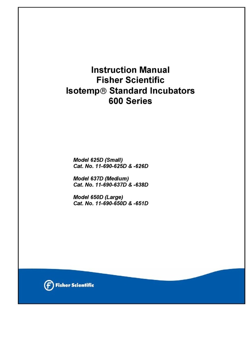
Instruction Manual
Fisher 500 Series
Isotemp
Incubator
Model 506D (Small)
11-690-506D (120V)
11-690-507D (240V)
Model (Large)
11-690-516D (120V)
11-690-517D (240V)
Manual Part Number 103044 Rev C Date 12/2002
1
Fisher 500 series IsotempIncubators are compact and
economically priced units. Designed to handle most of the basic
heating applications in the laboratory. The two models (0.6 ft3and
1.6 ft3) are controlled by an electronic temperature controller over
a temperature range of ambient + 5° to 60°C. A Safety Sentinel
temperature monitoring system is built in to protect valuable
specimens from damage. The safety assumes control of the
incubator, should the main temperature control fail.
Double wall construction with fiberglass insulation between the
steel outer cabinet and the aluminum inner chamber, reduces heat
loss and contributes to uniformity and consistency of chamber
temperature. All units are shipped with a full-width chrome-plated
shelf and are equipped with a door that opens 180°for easy
access to the chamber
Specifications
Temperature Range: ambient + 5° to 60°C
Control Sensitivity: ±0.5°C.
Electrical Requirements:
Model 506D: 120V, 50/60Hz, 1.8 Amps
230V 50-60Hz, 0.9 Amps
Model 516D: 120V, 50/60Hz, 2.2 Amps
230V 50Hz, 1.0 Amps
Heater Wattage:
Model 506D: 200W
Model 516D: 225W
Chamber Volume:
Model 506D: 0.6 ft3
Model 516D: 1.6 ft3
Chamber Size (Inches):
Model 506D: 11 W x 10 D x 10 H
Model 516D: 14 W x 14 D x 14 H
Area per Shelf:
Model 506D: 104.5 in2
Model 516D: 188.6 in2
Overall Size:
Model 506D: 13.4 W x 12.2 D x 17.6 H
Model 516D: 16.4 W x 16.2 D x 21.6 H
UNPACKING
The 500 Series IsotempGravity-Convected Incubator is shipped
fully assembled in a single carton containing the items listed
below. Should a shortage exist, notify your Fisher branch or
representative, supplying the description and part number of the
missing item; part numbers are listed in accessories and
replacement parts sections.
Note: In the event shipping damage has occurred, retain the
carton and packing material intact with the Incubator, and
immediately file a claim with the final carrier, Usually the carrier will
send an inspector to ascertain liability.
Qty Item
1 500 Series Incubator
1 Thermometer Bracket
1 Shelf
1
Instructions
Safety Precautions
Before operation, always observe the following Safety
precautions: This unit is not explosion proof. Do not use in
the presence of flammable or combustible materials; fire or
explosion may result. Unit contains components that may ignite
such materials. Do not place volatile items on the heater cover.
Fumes and spillage from acidic/basic solutions cause corrosion of
the aluminum chamber. Care should be taken to maintain neutral
pH at all times. The heater is located at the bottom of the
chamber under the heater cover. The heater cover is not intended
to be a shelf. Do not set items directly on heater cover. The
temperature of this surface is greater than set temperature.
INSTALLATION
After unpacking perform the following installation procedures.
1. Position the Incubator in a suitable location near an electrical
outlet.
Note: To ensure proper air circulation, a minimum clearance of
two inches should be provided around all sides of the incubator.
Also, allow clearance above the incubator for a thermometer.
1. Drop the supplied thermometer bracket in the exhaust port
atop the incubator. The bracket should be suspended in the
port by its two tabs.
2. Check that the POWER switch is set to the OFF position, and
then connect the line cord to an appropriate AC outlet.
Note: See data plate (located near the line cord) for voltage,
current, and line frequency specifications. Make sure that the
power requirements will not overload the AC circuit to which it will
be connected.
4. The Incubator requires no preliminary adjustments and is now
ready for operation. Depending on the customer application
and customer laboratory procedures an initial calibration may
be done at this point.
CONTROLS AND INDICATORS
All controls and indicators are located on the front panel, below the
chamber door. An electronic temperature controller controls the
500 Series Incubator with a built in automatic Safety Sentinel to
prevent temperature run away.
Power Switch: Controls all incubator power.
Temperature Controller: Controls temperature from ambient +5°
to 60°C
Power Indicator: Illuminates when the power switch is on
Heat Indicator: Illuminates when power is applied to the heaters.
Safety Sentinel: Illuminates when an over temperature condition
exists. This controller will activate automatically and take over
control of the incubator within 5°C of the original set temperature.
OPERATION
The 500 Series IsotempIncubator are electronically controlled
for operation at any temperature between ambient +5° and 60°C
as follows:
1. Depress the upper section of the power switch - power
indicator should light.
2. Set TEMPERATURE control to a dial position relative to the
desired temperature. The HEAT indicator light should light
and remain lit until the chamber temperature approaches the
controllers set-point, then cycle on and off with heater
operation.
3. Measure the Incubator temperature and adjust temperature
control until chamber stabilizes and the desired set point is
obtained.
Notes: After controlling at a given temperature, if the temperature
control is rotated CCW, the Safety Sentinel indicator will come on;
this is normal operation.
External surfaces do get hot during normal operation at higher
temperatures.
Upon initial installation and subsequent heat-up this Incubator may
produce an odor and trace evolution of non-toxic vapor that results
from the bake-out of the insulation binder. This is a normal
condition and is to be expected.
2
SERVICE
Fisher 500 Series IsotempIncubators are fabricated of high-
quality long-life components. However, even with normal use,
certain parts may need to be replaced. Information is provided
here to assist in disassembling the incubator for the removal and
replacement of these components. Included is a wiring diagram of
the electrical circuit, along with replacement procedures for the
heater, the temperature controller and the front panel components.
It is recommended that qualified personnel perform service
procedures. The following numbers are provided for additional
support:
Technical Service: 1-800-926-0505
Fisher Service Division: 1-800-395-5442
Fisher Sales Support: 1-800-766-7000
Replacing Heater
1. Disconnect power cord from AC outlet.
2. Remove thermometer bracket from the exhaust port of the
chamber.
3. Open chamber door and remove the shelf.
4. Disengage sensor probe from the clip on bottom panel at rear
of chamber.
5. Remove the two screws securing the bottom panel, then lift
the panel upward, carefully guiding sensor probe through
opening in panel, then remove panel from the chamber.
6. Remove the two nuts and the two washers securing the heater
leads, and then pull the lead terminals off the heater studs.
7. Remove the screws securing the heater to the cabinet, and
then lift the heater out of the cabinet.
8. Install the replacement heater and reassemble the incubator
by reversing the disassembly steps above.
Gaining Access to Front Panel Components
1. Disconnect power cord from AC outlet.
2. Remove thermometer bracket from the exhaust port of the
chamber.
3. Open chamber door and remove the shelf, then close and
secure door.
4. Lay the incubator on its side with the door hinges facing
upward.
5. Remove the four feet and any additional screws securing the
perforated bottom panel. Remove the panel by sliding it
forward; all front panel components should now be accessible.
Replacing Front Panel Switch
1. Gain access to the front panel components as previously
described.
2. Locate the defective POWER switch and remove the push-on
connectors from the components terminals.
Note: Mark the leads so that reconnection to the replacement
switch is identical to the original.
3. Depress the locking tabs at the top and bottom of the switch
and remove the component through the front panel.
4. Insert the replacement switch through the front panel so that
the locking tabs snap open to secure the component in place.
5. Reconnect switch leads observing the conditions noted after
step 1.
6. Reassemble by reversing the applicable disassembly steps
described above.
Replacing Temperature Controller
1. Gain access to the front panel components as previously
described.
2. Remove the in-chamber temperature sensor from the clip and
lower through the hole, to the underside of the unit.
3. Remove the knob from the temperature set dial, along with the
locking nut.
4. Remove the 4 screws that secure the control board to the front
panel.
Note: Mark the leads so that reconnection to the replacement
controller is identical to the original.
5. Remove the push-on connectors and remove controller board.
6. Install the replacement control by generally reversing the
appropriate disassembly steps above.
7. To position the control knob, rotate the control knob fully
CCW, then secure the knob to the shaft with the pointer lined
up with the first line in the CCW position. Make sure the
sensor bead is lined up with the hole on the incubator floor.
Replacing the Thermocouple
1. Unclip the sensor at the bottom of the unit and lower through
the hole at the bottom of the chamber.
2. Observe the thermocouple terminal location and conductor
color (Yellow +, Red -). Disconnect old and connect new.
3. Position the new sensor in the chamber. Make sure that the
sensor bead is lined up with the hole on the unit floor.
Calibrating of Temperature Controller
The temperature controller can be calibrated by adjusting the HI
and LO temperature potentiometers located under the skirt of the
set temperature knob. Calibration can be accomplished per the
following instructions:
1. Set the unit temperature control to position 2. Carefully remove
the knob without rotating it.
2. Slowly adjust the LO potentiometer CCW until the heat
indicator comes on, then rotate CW slowly until the heat
indicator just goes out.
Note: The heat indicator should come on at a setting of 2 with a
unit temperature of between 25°and 35°C
3. Reinstall the knob and rotate it full CCW, the Safety Sentinel
indicator should come on.
4. To set the upper temperature range, set the temperature
control knob to position 18. Allow about 1 hour to completely
stabilize, the unit temperature should be at 65°C ±5°C. If it is
not in this range continue the calibration procedure.
5. Carefully remove the knob without rotating it and adjust the HI
potentiometer while observing the temperature and the heat
indicator. Adjustments should be made in small increments to
allow the incubator to stabilize. Adjust the hi potentiometer CW
to increase temperature.
6. Reinstall the knob and rotate it CCW to position 17, the Safety
Sentinel indicator should come on.
7. Repeat as necessary to obtain desired results within the
controller’s limitations.
REPLACEMENT PARTS
Item Number
Heater Assembly:
506D 120V SPN 103019
230V SPN 103086
516D 120V SPN 60761
230V SPN 64190
Power Switch SPN 83373
Temperature Controller: 120V SPN 83371
240V SPN 88195
Knob, Controller SPN 32615
Thermometer Bracket SPN 37768
Thermocouple SPN102715
3
Trouble-Shooting
This table is intended to assist in resolving incubator problems by relating symptoms to their likely causes. The service discussed below is
beyond the scope of most users and should be performed by qualified personnel.
Service procedures requiring access to the electronics compartment involve exposure to line voltage and should be done by
qualified service personnel. Disconnect incubator from power before attempting repairs.
Symptom Probable Cause Action
No power Unit not plugged in.
Unit not turned on.
Defective circuit breaker.
Defective Control Board
Plug unit into power supply. Verify voltage at the plug with a voltmeter.
Press the ON/OFF switch to ON ( | )
If voltage is present and the switch is on and no LED’s, open bottom cover to
expose the wiring.
Verify voltage is available at the control board. Replace circuit breaker if no
voltage is available at the control board.
If voltage at control board and no LED’s are on. Replace control board
Incubator
temp
erratically high
Defective thermocouple.
Shorted thermocouple.
Open thermocouple
Defective controller.
Unplug the unit and check thermocouple by:
1. Connection to control board.
2. Visually check thermocouple insulation open (conductors that touch can give
false readings and confuse the controller). Replace thermocouple if insulation
open (Except at tip inside incubator).
3. Disconnect and perform continuity less than 20 ohms between 2 leads. If
open (greater than 20 ohms), Replace thermocouple.
If less than 20 ohm from last step, Replace controller.
Failure to heat
No LED’s (No power)
Set temp is below actual temp. (Power LED on
and Safety LED on)
Defective heater.
Defective wiring
Defective Thermocouple
Defective controller.
See No power Above
Change set temperature or wait unit cools below set temp. (Power LED on and
safety LED on)
To verify control is operational do the following:
1. Empty incubator (no customer samples in unit) and open wiring compartment.
2. Turn control to max temperature and verify line voltage across “heater” to
“safety”.
3. If voltage present, turn off power and perform a continuity check by lifting one
lead of the heater. Verify the resistance is less than 100 ohm for 120V units and
less than 300 ohm for 240V units.
4. If greater or open continuity is indicated, open heater cover and repeat at
heater. If still greater replace heater.
5. If ok check /replace wiring to heater.
See Defective thermocouple above.
Figure 1 Schematics
ACCESSORIES
Item Catalog Number
Thermometer, 40°to 240°C 11-682-30
Shelf for:
11-690-506D, -507D 13-245-6S
11-690-516D, -517D 13-245-15S
Fisher Scientific Assistance
Fisher Technical Service: 1-800-926-0505
Fisher Service Division: 1-800-395-5442
Fisher Sales Support: 1-800-766-7000
Manual Part Number 103044 Rev C Date 12/2002

Other manuals for Isotemp 500 Series

1

This manual suits for next models

5

Other Fisher Scientific Accessories manuals

Fisher Scientific Isotemp 178L 120V User manual

Fisher Scientific

Fisher Scientific Isotemp 178L 120V User manual

Fisher Scientific Isotemp Series User manual

Fisher Scientific

Fisher Scientific Isotemp Series User manual

Fisher Scientific Isotemp 600 Series User manual

Fisher Scientific

Fisher Scientific Isotemp 600 Series User manual

Fisher Scientific Isotemp 500 Series User manual

Fisher Scientific

Fisher Scientific Isotemp 500 Series User manual

Fisher Scientific Isotemp 60L Incbtr Grvity 120V User manual

Fisher Scientific

Fisher Scientific Isotemp 60L Incbtr Grvity 120V User manual

Fisher Scientific 3530 User manual

Fisher Scientific

Fisher Scientific 3530 User manual

Fisher Scientific 146E User manual

Fisher Scientific

Fisher Scientific 146E User manual

Popular Accessories manuals by other brands

CKD WFC Series instruction manual

CKD

CKD WFC Series instruction manual

Ferguson FS2CO user manual

Ferguson

Ferguson FS2CO user manual

FlowLine EchoPro LR36 Series quick start

FlowLine

FlowLine EchoPro LR36 Series quick start

SunSetter Gaviota Upgrade instructions

SunSetter

SunSetter Gaviota Upgrade instructions

Sense XS manual

Sense

Sense XS manual

Harbor Freight Tools 38335 instruction manual

Harbor Freight Tools

Harbor Freight Tools 38335 instruction manual

Helite H-MOOV user guide

Helite

Helite H-MOOV user guide

Beurer WL 32 Instructions for use

Beurer

Beurer WL 32 Instructions for use

LORENZ MESSTECHNIK IPE 50 Series user manual

LORENZ MESSTECHNIK

LORENZ MESSTECHNIK IPE 50 Series user manual

Sentry WF001 manual

Sentry

Sentry WF001 manual

Panasonic PE Series instruction manual

Panasonic

Panasonic PE Series instruction manual

optris S20 Operator's manual

optris

optris S20 Operator's manual

BenQ PD03 quick start guide

BenQ

BenQ PD03 quick start guide

Montech TB30 Assembly instructions

Montech

Montech TB30 Assembly instructions

FAE 24761 Assembly instructions

FAE

FAE 24761 Assembly instructions

AKCP Airflow user manual

AKCP

AKCP Airflow user manual

Hive Motion Sensor user guide

Hive

Hive Motion Sensor user guide

NeuLog NUL-207 Guide

NeuLog

NeuLog NUL-207 Guide

manuals.online logo
manuals.online logoBrands
  • About & Mission
  • Contact us
  • Privacy Policy
  • Terms and Conditions

Copyright 2025 Manuals.Online. All Rights Reserved.