Fisher Scientific Mini300V Plus User manual

1
Mini300V Plus Power Supply
Instruction manual
Mini300V Plus
Version 01
May 2012

2
Packing list
Mini300V Plus
-1x Mini300V Plus Power Supply
-1x Power Cord
-1x Instruction Manual
Signed by:
Date:

3
Warning
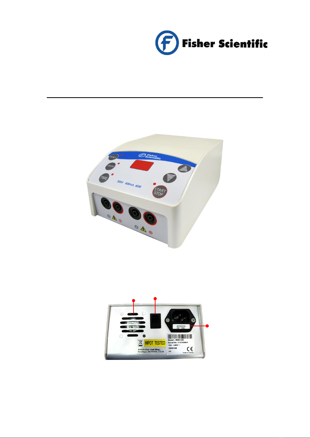
The MINI300V PLUS Power Supply has been thoroughly tested and found to
comply within the limits of CE regulation. It has been manufactured using the
latest technology and does not require maintenance. When used correctly
this unit poses no particular health risk, although it can deliver dangerous
voltage levels if used incorrectly. Accordingly, this power supply must only be
operated by fully qualified personnel adhering to the guidelines laid out within
this instruction manual. Although this power supply is equipped with all
necessary safety features against abuse and accidental failure, caution should
always be exercised when working with high voltage equipment. Any
individual intending to use this instrument should read the entire manual
thoroughly before operation.
1. Read the instruction manual thoroughly before use.
2. Never touch the power outlets with any conductive object (e.g. naked
metal wire) other than properly insulated power supply cables.
3. Do not spill liquid or insert metal objects inside the power supply.
4. Never block the ventilation holes or place the unit in any enclosure unless
there is adequate ventilation; never expose the power supply to a direct
heat source.
5. Never touch any part of the power supply assembly (i.e. power supply,
cables or electrophoresis tank) before switching OFF the power supply.
6. Never manipulate with wet hands.
7. Do not connect to ground any of the power outputs or the buffer within the
electrophoresis tank; the power outputs should be only connected to an
insulated electrophoresis tank equipped with a safety cover.
8. Do not connect any power supplies in series or in parallel.
9. Never open the back plate or remove the cover, otherwise an electric
shock may result. Repairs should only be made by the manufacturer or a
service technician authorised by the manufacturer.
10. Never use this power supply if the safety cover is not in position correctly.
11. Do not use the unit if there is any sign of damage to the external tank or
cover. Contact the manufacturer or supplier immediately to replace or

4
repair any damaged parts.
12. Never use the power supply in the presence of flammable or combustible
material as fire or explosion may result.
13. Ensure that the power supply is only connected to an earthed power line.
Do not cut and splice the power line. When removing the power cord
from the wall, unplug it by holding the plug attachment and not by pulling
the cord. Do not hold the plug with wet hands or gloves.
Environmental Conditions
This power supply may only be installed and operated only under the following
environmental conditions:
1. For indoor use only
2. Relative humidity: ≤95%
3. Atmospheric pressure: 75 kPa –106 kPa
4. Altitude: ≤2000 metres
5. Operating temperature: ambient to 40°C
6. Pollution degree: 2
7. Mains supply voltage fluctuations up to ±10% of the normal voltage
Symbols
The symbols used on the power supply are explained below.
Indicates the potential for electric shock.
Consult the manual to avoid possible personal injury or instrument
damage.
Do not dispose of this power supply in municipal or domestic waste
once it has reached the end of its lifespan. Please recycle it if
possible.

5
Table of Contents
Packing list...............................................................................................................2
Warning.....................................................................................................................3
Section 1 Introduction......................................................................................6
1.1 Overview..........................................................................................................6
1.2 Product description & Feature.........................................................................7
Section 2 Technical Specification...................................................................8
Section 3 Installation Instructions ..................................................................9
Section 4 Operation Instructions....................................................................9
4.1 Control interface ..............................................................................................9
4.2 Start the operation .........................................................................................10
4.3 To use the constant current or voltage mode................................................ 11
4.4 To adjust the time………………………………………………………………... 11
4.5 Starting and stopping the run……………………………………………………11
Section 5 Troubleshooting and Maintenance..................................................... 12
Section 6 Ordering Information ............................................................................... 16
Section 7 Warranty ....................................................................................................... 16

6
Section 1 Introduction
1.1 Overview
Front view
Rear view
Main power socket &
Fuse holder
ON/OFF Switch
Fan

7
1.2 Product Description & Features
With enhanced features, such as a maximum constant current output of
400mA, in addition to constant voltage up to 300V, the MINI300V PLUS is
capable of running all Fisher Scientific horizontal Sub-gel and vertical Verti-gel
mini gels, either on a continuous run or timed setting up to 999 minutes. The
MINI300V PLUS’s user-friendly interface is easily adjustable in 1V and 1mA
increments, making it perfect for separations where precise settings are
required, while its ultra-compact size and two pairs of parallel power terminals,
which can run two electrophoresis units simultaneously, save time and bench
space. A dual voltage rating ensures full portability, and allows easy
transportation between laboratories irrespective of their geographical location.

8
Section 2 Technical Specification
Output range (programmable)
Voltage
10-300V
Current
10-400mA
Power
60W max.
Resolution
1V / 1mA
Type of Output
Constant voltage or constant current
Automatic crossover
-
Timer
1-999 min. with alarm; Continuous
Pause/resume function
-
Display
3-digit LED
Programmable Methods
-
Automatic recovery after power failure
-
Safety features
No-load detection; over-voltage, current &
temperature protection;
maximum power output detection; shrouded
plugs and sockets
Operating conditions
Ambient-40C; ≤95% humidity
Stackable
-
Number of output jacks
2 sets in parallel
Regulatory conformity
EN-61010-1; CE
Dual voltage
Yes; 100-240 VAC
Construction
Polycarbonate housing with aluminium base
Dimensions (WxDxH)
140x191x84mm
Weight
1Kg

9
Section 3 Installation Instructions
The MINI300V PLUS Power Supply is a factory pre-installed instrument. The
power supply is ready for immediate use once it is unpacked and placed on a
level, dry bench surface that is adequately ventilated and away from sources
of direct heat.
Section 4 Operation Instructions
4.1 Control interface
There are six buttons and four LED indicators on the faceplate.
The LED indicates the operation status of the unit.
a. Setup Mode (before pressing RUN/Start)
Each illuminated LED light shows the parameter currently selected on the
faceplate of the power supply. For example, if the voltage is selected the
VOLT LED will be illuminated.

10
b. Operation Mode
Once the power supply is started, the LED will be illuminated on the
faceplate adjacent to the START/STOP button.
1. –Voltage Select
2. –Current Select
3. –Time Select
4. –Increase Select
5. –Decrease Select
6. –Start/Stop Program
4.2 To start the operation
Note: To operate under constant voltage or constant current modes, adjust the
other parameter to the maximum value. For example, to operate under
constant voltage, adjust the current to the maximum output of 400mA before
running the power supply with the voltage set at the desired output setting.
1. Place the power supply on a level, dry bench surface away from sources of
direct heat.
2. With theAC power switch in the OFF position, plug the power cord into a
grounded AC outlet of the appropriate voltage (i.e. 100V or 240V,
determined by the rating sticker near the AC cord on the back of the unit).
3. Switch on the power supply by pressing the ON/OFF button at the rear of
the power supply.

11
4. Connect the power supply cables from the electrophoresis unit by inserting
the red lead (+) into the red power supply output and the black lead (-) into
the black power supply output beneath the front fascia plate.
4.3 To use the constant voltage or current mode
* Press the or buttons to set a constant voltage or current
respectively.
5. Press the or buttons to adjust the voltage or current in 1V or
1mA increments or decrements to the required output value.
6. After adjusting your constant mode output value (e.g. voltage), set the other
parameter to the maximum output (e.g. current).
4.4 To adjust the time
7. After setting the desired current or voltage output value, press the
button, and then press key or key to adjust timer accordingly.
For non-stop continuous operation, set the button to ‘zero’.
4.5 Starting and stopping the run
8. Press the key to start the run. Once the electrophoresis run starts,
the LED light will light up next to the button.

12
9. Press the key again to stop the unit at any time during the run if it is
necessary to access the gel tank. Press the key to resume
electrophoresis.
10.Press the key to terminate a timed run, and turn the AC power OFF
using the switch at the rear of the power supply.
11.The programmed settings will be retained within power supply memory and
displayed when the power supply is next switched on.
Section 5 Troubleshooting and Maintenance
Many operating problems may be solved by reading and following the instructions in
this manual accordingly. Some suggestions for troubleshooting are given below. If
these suggestions fail to resolve the problem, contact the Fisher Scientific distributor
in your region for assistance. If troubleshooting service is required, please include a
full description of the problem.
Problem
Cause
Solution
No Display / lights
No AC power
Check if the power supply is unplugged,
or if the AC power source is a problem.
AC power cord is not
connected
Check AC power cable to ensure that it is
fits correctly within the power supply. Use
the correct power cable.
The fuse has blown
Replace the fuse.
Fuse repeatedly
broken
Hardware failure
Contact the Fisher Scientific’s service
department.

13
Operation stops
Electrophoresis cables
are not connected to
the power supply or to
the electrophoresis
unit(s). There is a
broken circuit in the
electrophoresis tank.
Check the connections to the power
supply and the electrophoresis tank to
ensure they are intact; check the
condition of wires in the electrophoresis
unit. Close the circuit by reconnecting
the cables. Press START/STOP to
resume the run.
High resistance due to
tape left on a pre-cast
gel; an incorrect buffer
concentration or
volume in the
electrophoresis tank
Ensure that any tape is removed from the
ends of a pre-cast gel, the buffers are
prepared correctly, and the recommended
volume of buffer is added to the
electrophoresis tank.
Error message
Current exceeds the
maximum output for
the power supply
(>400mA)
Check if the buffer concentration or
molarity is appropriate. Excessive buffer
concentration or molarity may increase
conductivity. To clear the error message,
press the START/STOP button.
Error message
Voltage exceeds the
maximum output for
the power supply
(>300V)
Press the START/STOP button to clear
the error message. Contact Fisher
Scientific’s service department if the
problem persists.
Error message
Thermal limitation of
the power supply
reached (Output
voltage <10V)
(1) Check the connections
(2) If the Er3 error message persists, the
problem may be caused by internal fan
failure. Contact the Fisher Scientific’s
service department.
Message
No load is detected
(1) Check the connections
(2) Check the buffer condition / buffer
level
Alarm message
Power exceeds the
maximum output (60W)
Warning message for reference

14
Encountering Problems
1. Check the troubleshooting section.
2. Call or email Technical Service.
3. If it is necessary to ship the unit back for repair, contact Fisher Scientific’s
service department for a Return Authorisation Number (RAN) and shipping
instructions. The unit will be repaired and returned to you as quickly as
possible.
Replacing the Fuse
For additional fuses, please contact Fisher Scientific Ltd.
To replace the fuse:
1. Turn off the main power switch at the rear of power supply and detach the
power cord.
2. Open the fuse compartment located inside the Power Entry Module by
inserting a small flat-bladed screwdriver into the slot below the ON/OFF
switch at the rear of the power supply. Gently turn the screwdriver to pry
open the fuse compartment.
Note: The fuse compartment will not open with the power cord in place.
3. Pull the fuse holder out of the compartment and inspect the fuse. If the fuse
is burnt or there is a break in the fuse element, replace the fuse with an
identical type of fuse (T2AH250V; as shown in the figure below).
4. Place the fuse holder back into the compartment.
5. Snap the cover closed.

15
Maintenance
The MINI300V PLUS Power Supply uses all solid-state components and
should require no maintenance or recalibration under normal use. If the unit
must be returned for repair, contact your local authorised Fisher Scientific
distributor.

16
Section 6 Ordering Information
Cat. No. Description
FB79520 Fisher Scientific MINI300V PLUS, 300V, 400mA, 60W
Power Supply, 110-240 VAC

17
Section 7 Warranty
Fisher Scientific Ltd. Power Supplies have a warranty against manufacturing
and material faults of twelve months from the date of customer receipt.
If any defects arise during this warranty period, Fisher Scientific will repair or
replace the defective parts free of charge.
This warranty does not cover defects resulting from accident or misuse, or
defects caused by improper operation.
Units where repair or modification has been performed by anyone other than
Fisher Scientific, or an appointed distributor or representative, are no longer
under warranty from the time the unit was modified.
Warranty is rendered invalid for those units which contain accessories or
repaired parts not supplied by Fisher Scientific or its associated distributors.
Fisher Scientific cannot repair or replace free of charge units where improper
solutions or chemicals have been used.
If a problem does occur then please contact your nearest Fisher Scientific
supplier.
Table of contents
Other Fisher Scientific Power Supply manuals

Fisher Scientific
Fisher Scientific FB200-2 User manual

Fisher Scientific
Fisher Scientific FB1000-2 User manual

Fisher Scientific
Fisher Scientific FB300 User manual

Fisher Scientific
Fisher Scientific Midi300V/4 User manual

Fisher Scientific
Fisher Scientific FB1000 User manual

Fisher Scientific
Fisher Scientific FB300-2 User manual
Popular Power Supply manuals by other brands

Pulsar
Pulsar PSB251215 quick start guide

Spectrum
Spectrum SPB 5L14.4 Installation and operational guide

twintex
twintex TFC8000 Series Operation manual

Beckhoff
Beckhoff PS1061-2405-0000 Documentation

Fire-Lite Alarms
Fire-Lite Alarms APS-6RF installation instructions

Alpha
Alpha BROADBAND UPS XM3.1-HP quick start guide