www.Fisher.com
D102803X012
Type 249W Cageless Wafer Style Level Sensor
Contents
Introduction 1. . . . . . . . . . . . . . . . . . . . . . . . . . . . . . .
Scope of Manual 1. . . . . . . . . . . . . . . . . . . . . . . . . .
Description 1. . . . . . . . . . . . . . . . . . . . . . . . . . . . . . .
Type Number Description 2. . . . . . . . . . . . . . . . . .
Educational Services 3. . . . . . . . . . . . . . . . . . . . . .
Installation 3. . . . . . . . . . . . . . . . . . . . . . . . . . . . . . . .
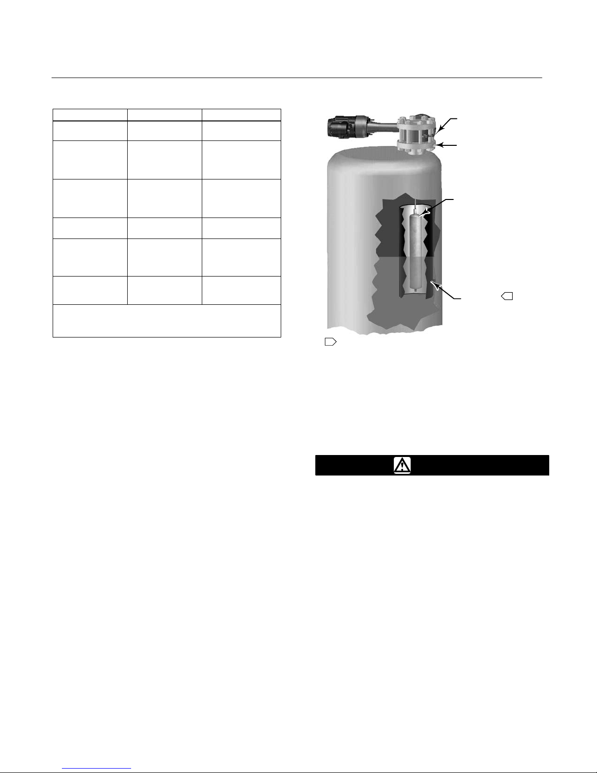
Installation on Top of Vessel 4. . . . . . . . . . . . . . . .
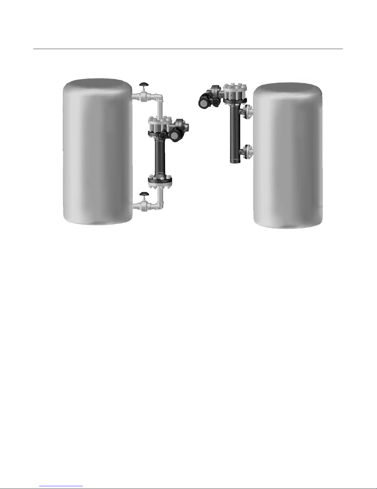
Installation with Displacer Cage
on Side of Vessel 4. . . . . . . . . . . . . . . . . . . . . . .
Mounting the Sensor on the Process
Vessel or Displacer Cage 5. . . . . . . . . . . . . . . .
Maintenance 10. . . . . . . . . . . . . . . . . . . . . . . . . . . . .
Removing the Displacer and Stem 12. . . . . . . . . .
Replacing the Displacer, Cotter Spring,
Stem End Piece, and Displacer Spud 12. . . . .
Replacing the Displacer Rod/Driver Assembly 13
Replacing the Torque Tube 13. . . . . . . . . . . . . . . .
Replacing the Torque Tube Arm and
Changing the Mounting 14. . . . . . . . . . . . . . . . .
Simulation of Process Conditions for Calibration
of Level-TrolRControllers and Transitters 15. .
Parts Ordering 16. . . . . . . . . . . . . . . . . . . . . . . . . . . .
Determining Displacer Stem Length 16. . . . . . . .
Parts List 17. . . . . . . . . . . . . . . . . . . . . . . . . . . . . . . .
Introduction
Scope of Manual
This instruction manual includes maintenance, and
parts ordering information for the Type 249W
cageless wafer style sensor.
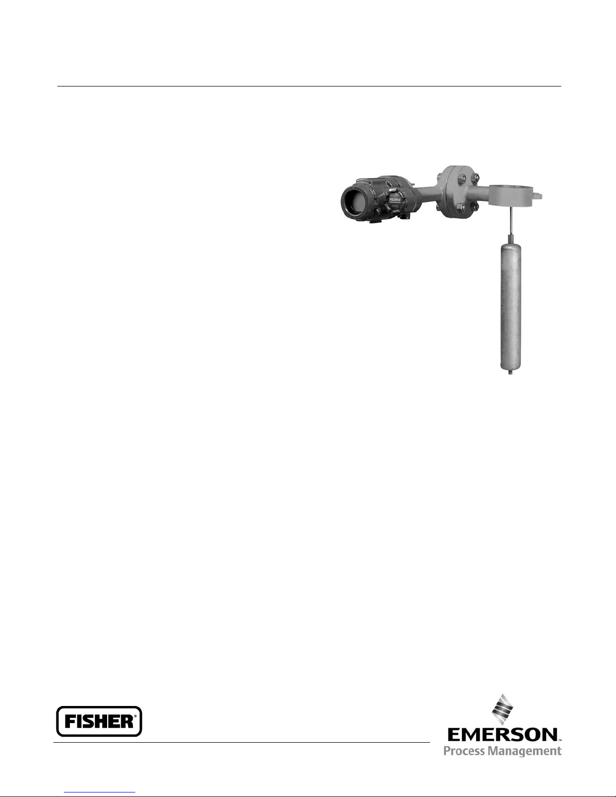
Although the sensor is usually shipped with attached
controller or transmitter, as shown in figure 1, this
manual does not include operation, installation,
calibration, maintenance, and parts ordering
information for the controller/transmitter or for the
complete unit. For this information, refer to the
appropriate controller/ transmitter instruction manual.
W8231 / IL
Figure 1. Type 249W Sensor with DLC3000 Series
Digital Level Controller
No person may install, operate, or maintain a Type
249W sensor and the attached controller or
transmitter without first Dbeing fully trained and
qualified in valve, actuator, and accessory
installation, operation and maintenance, and D
carefully reading and understanding the contents of
this manual. If you have any questions concerning
these instructions, contact your Emerson Process
Managementtsales office before proceeding.
Description
The Type 249W sensor is designed to measure
liquid level, interface level, or density/specific gravity
inside a process vessel.
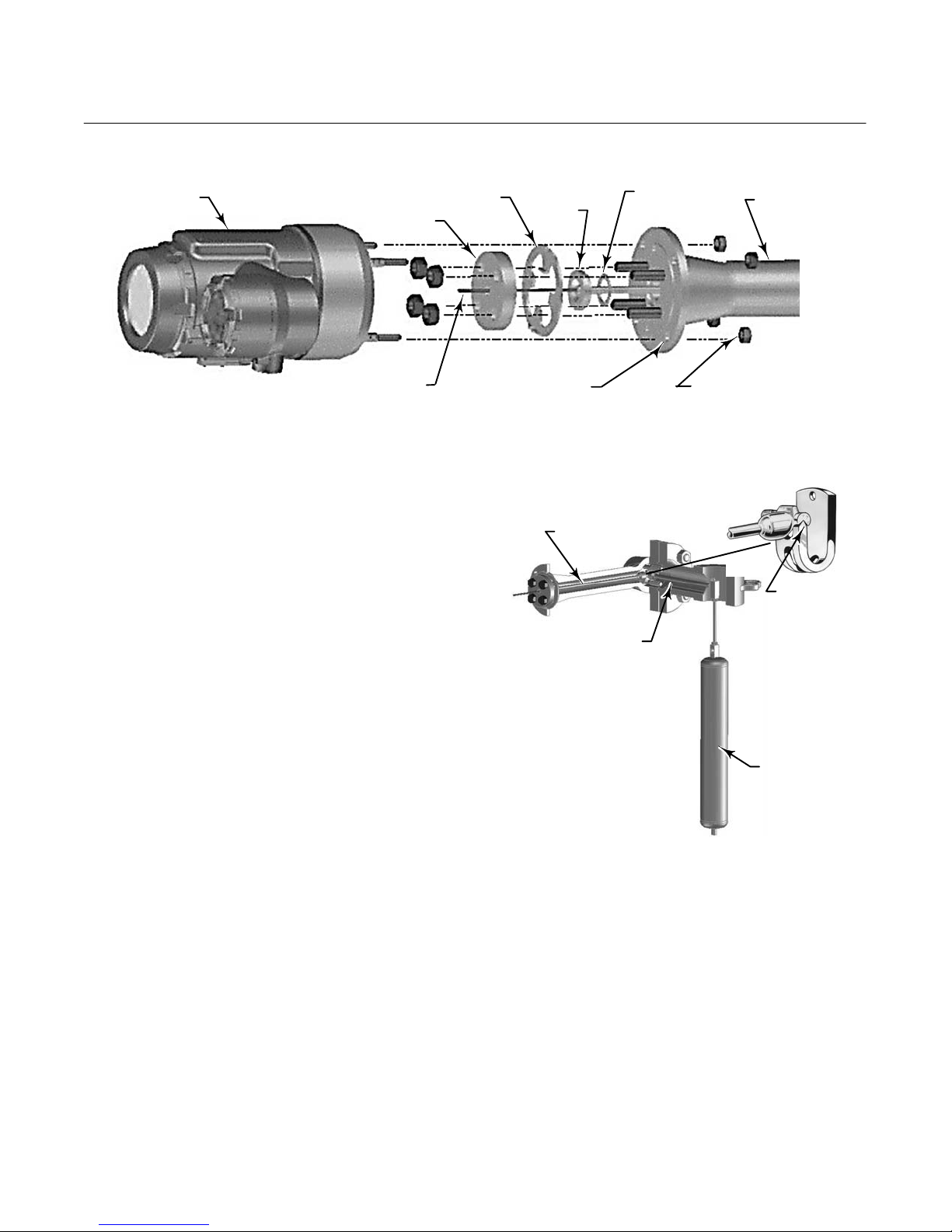
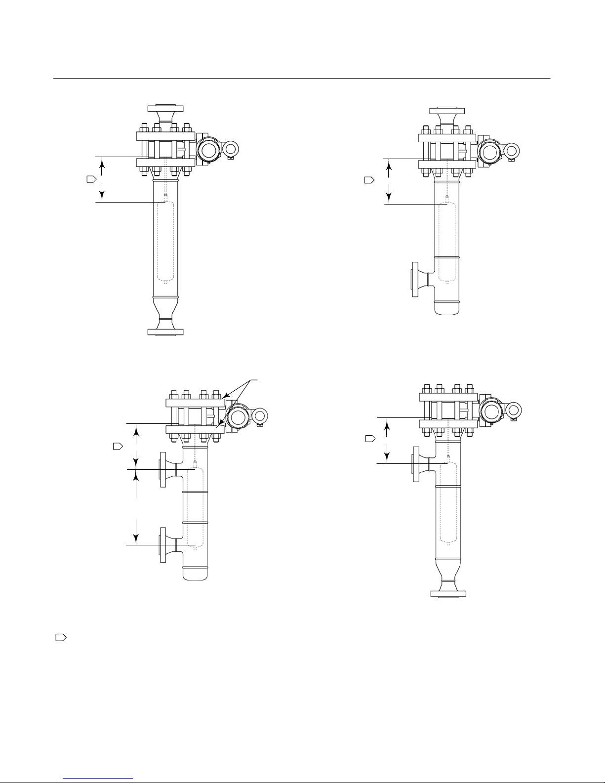
A torque tube assembly (figure 3) and displacer
provide an indication of liquid level, interface level, or
density/specific gravity. The torque tube assembly
consists of a hollow torque tube with a shaft welded
inside it at one end and protruding from it at the
other end.
Instruction Manual
Form 5729
May 2006 249W Level Sensor