Fisher XLS 74800 User manual

A DIVISION OF FISHER, LLC
CAUTION
Read this document before installing the
snowplow.
CAUTION
See your FISHER®outlet/website for specific
vehicle application recommendations before
installation. The eMatch selection system has
specific vehicle and snowplow requirements.
XLS™ Snowplow‡
Installation Instructions
Fisher Engineering
January 15, 2019
Lit. No. 85501, Rev. 02
74800, 74810, 74850
79810, 79850, 87800
50 Gordon Drive, Rockland, Maine 04841-2139 • www.fisherplows.com
‡Snowplows with serial numbers beginning with 180210 and higher.

Lit. No. 85501, Rev. 02 2 January 15, 2019
74800, 74810, 74850, 79810, 79850, 87800
SAFETY DEFINITIONS
NOTE: Indicates a situation or action that can lead
to damage to your snowplow and vehicle or other
property. Other useful information can also be
described.
CAUTION
Indicates a potentially hazardous situation
that, if not avoided, may result in minor or
moderate injury. It may also be used to alert
against unsafe practices.
WARNING/CAUTION & INSTRUCTION
LABELS
Become familiar with and inform users about the
warning labels on the back of the blade and the
instruction label on the headgear.
NOTE: If labels are missing or cannot be read, see
your sales outlet.
WARNING
Indicates a potentially hazardous situation
that, if not avoided, could result in death or
serious personal injury.
Warning/Caution Label
Instruction Label
Multiple Pinch Points Label
(Both ends of blade)

Lit. No. 85501, Rev. 02 3 January 15, 2019
74800, 74810, 74850, 79810, 79850, 87800
HYDRAULIC SAFETY
• Always inspect hydraulic components and hoses
before using. Replace any damaged or worn parts
immediately.
• If you suspect a hose leak, DO NOT use your
hand to locate it. Use a piece of cardboard or
wood.
FUSES
The FISHER®electrical and hydraulic systems
contain several automotive-style fuses. If a problem
should occur and fuse replacement is necessary,
the replacement fuse must be of the same type and
amperage rating as the original. Installing a fuse with
a higher rating can damage the system and could start
a fire. Fuse Replacement, including fuse ratings and
locations, is located in the Maintenance section of the
Owner's Manual.
PERSONAL SAFETY
• Remove the ignition key and put the vehicle in
PARK or in gear to prevent others from starting
the vehicle during installation or service.
• Wear only snug-fitting clothing while working on
your vehicle or snowplow.
• Do not wear jewelry or a necktie, and secure long
hair.
• Wear safety goggles to protect your eyes from
battery acid, gasoline, dirt, and dust.
• Avoid touching hot surfaces such as the engine,
radiator, hoses, and exhaust pipes.
• Always have a fire extinguisher rated BC handy,
for flammable liquids and electrical fires.
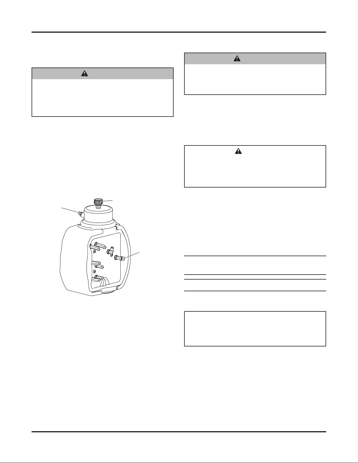
WARNING
Hydraulic fluid under pressure can cause skin
injection injury. If you are injured by hydraulic
fluid, get medical attention immediately.
SAFETY PRECAUTIONS
Improper installation and operation could cause
personal injury and/or equipment and property damage.
Read and understand labels and the Owner's Manual
before installing, operating, or making adjustments.
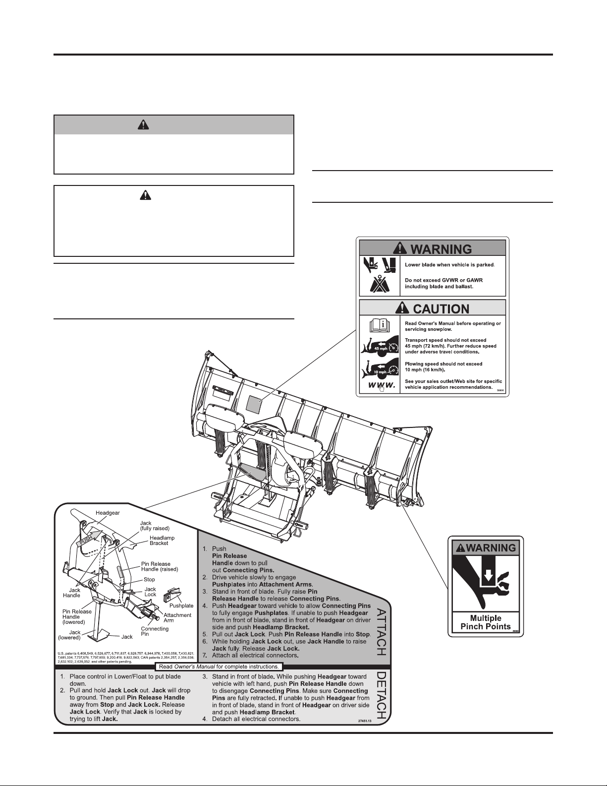
WARNING
Lower the blade when the vehicle is parked.
Temperature changes could change
hydraulic pressure, causing the blade to
drop unexpectedly or damaging hydraulic
components. Failure to do this could result in
serious personal injury.
WARNING
Remove blade assembly before placing
vehicle on hoist.
WARNING
The driver shall keep bystanders clear of the
blade when it is being raised, lowered, or
angled. Do not stand between the vehicle and
the blade or within 8 feet of a moving blade. A
moving or falling blade could cause personal
injury.
WARNING
Do not exceed GVWR or GAWR including
blade and ballast. The rating label is found on
driver-side vehicle door cornerpost.
WARNING
To prevent accidental movement of the blade,
always turn the control OFF whenever the
snowplow is not in use. The power indicator
light will turn OFF.
WARNING
Keep hands and feet clear of the blade and
A-frame when mounting or removing the
snowplow. Moving or falling assemblies could
cause personal injury.
CAUTION
Refer to the current eMatch selection system
for minimum vehicle recommendations and
ballast requirements.
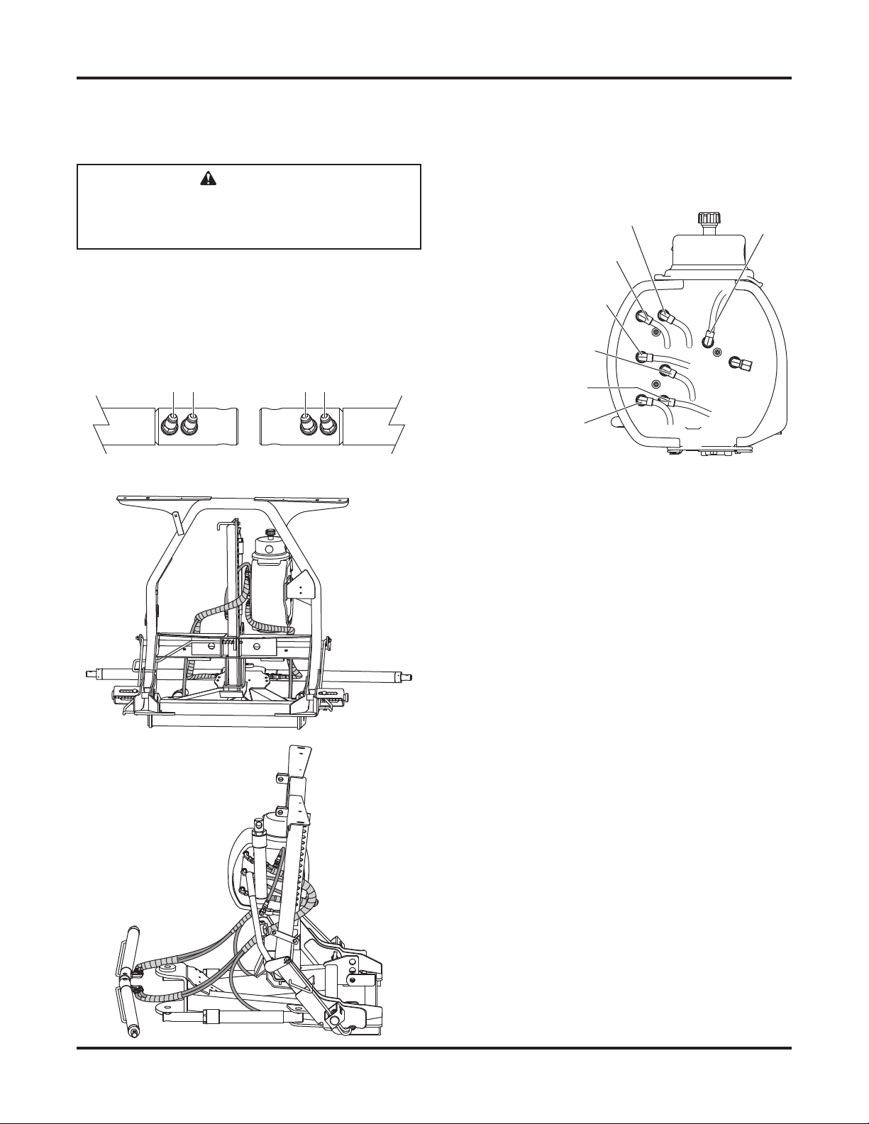
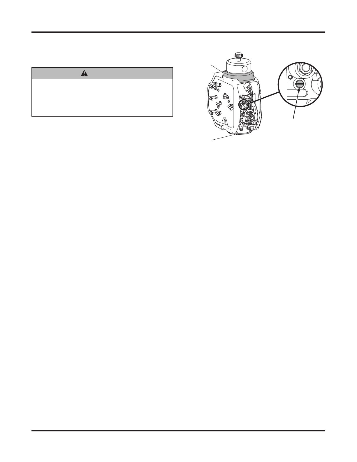
CAUTION
Assembling a hose to the incorrect wing ram
port can result in permanent damage to the ram.

Lit. No. 85501, Rev. 02 4 January 15, 2019
74800, 74810, 74850, 79810, 79850, 87800
FIRE AND EXPLOSION
Be careful when using gasoline. Do not use gasoline
to clean parts. Store only in approved containers away
from sources of heat or flame.
CELL PHONES
A driver's first responsibility is the safe operation of
the vehicle. The most important thing you can do
to prevent a crash is to avoid distractions and pay
attention to the road. Wait until it is safe to operate
Mobile Communication Equipment such as cell phones,
text messaging devices, pagers, or two-way radios.
VENTILATION
BATTERY SAFETY
NOISE
Airborne noise emission during use is below 70 dB(A)
for the snowplow operator.
VIBRATION
Operating snowplow vibration does not exceed 2.5 m/s2
to the hand-arm or 0.5 m/s2to the whole body.
TORQUE CHART
1/4-20 109 154
1/4-28 121 171
5/16-18 150 212
5/16-24 170 240
3/8-16 269 376
3/8-24 297 420
7/16-14 429 606
7/16-20
9/16-12
9/16-18
5/8-11
5/8-18
3/4-10
3/4-16
7/8-9
7/8-14 474 669
644 9091-8
1-12 704 995
1/2-13
1/2-20
11.9
13.7
24.6
27.3
43.6
26.9
53.3
93
148
49.4
69.8
77.9
106.4
120.0
8.4
9.7
17.4
19.2
30.8
35.0
49.4
55.2
75.3
85.0
M6 x 1.00
M12 x 1.75
M8 x 1.25
M14 x 2.00
M10 x 1.50
M27 x 3.00
M22 x 2.50
M30 x 3.50
M24 x 3.00
M20 x 2.5011.1
19.5
38.5
67
107
7.7
613
778
1139
1545
450
428
562
796
1117
M33 x 3.50
M36 x 4.00
2101
2701
1468
1952
325
M16 x 2.00 231
167
M18 x 2.50 318222
Recommended Fastener Torque Chart
Size Size
Torque (f t- lb)
Grade
5
Grade
8
Metric Fasteners Class 8.8 and 10.9
These torque values apply to fasteners
except those noted in the instructions.
Torque (f t- lb)
Grade
5
Grade
8
Size Size
Torque (f t- lb)
Class
8.8
Class
10.9
Torque (f t- lb)
Class
8.8
Class
10.9
Inch Fasteners Grade 5 and Grade 8
CAUTION
Batteries normally produce explosive gases,
which can cause personal injury. Therefore,
do not allow flames, sparks, or lit tobacco
to come near the battery. When charging or
working near a battery, always cover your
face and protect your eyes, and also provide
ventilation.
• Batteries contain sulfuric acid, which burns
skin, eyes, and clothing.
• Disconnect the battery before removing or
replacing any electrical components.
CAUTION
Read instructions before assembling.
Fasteners should be finger tight until
instructed to tighten according to the torque
chart. Use standard methods and practices
when attaching snowplow, including proper
personal protective safety equipment.
WARNING
Vehicle exhaust contains lethal fumes.
Breathing these fumes, even in low
concentrations, can cause death. Never
operate a vehicle in an enclosed area without
venting exhaust to the outside.
WARNING
Gasoline is highly flammable and gasoline
vapor is explosive. Never smoke while
working on vehicle. Keep all open flames
away from gasoline tank and lines. Wipe up
any spilled gasoline immediately.

Lit. No. 85501, Rev. 02 5 January 15, 2019
74800, 74810, 74850, 79810, 79850, 87800
HEADGEAR TO A-FRAME ASSEMBLY
NOTE: For easier assembly and installation,
vehicle and all snowplow components should
be on a smooth, level, hard surface, such as
concrete.
1. With the vehicle parked on a solid level surface,
measure the distance from the center of the
connecting pin hole to the ground. Using this
measurement, refer to the hole selection chart
below to determine which hole should be used to
attach the headgear to the A-frame.
Pushplate Height
(hole center to ground)
Rear
Hole
17" to 19" Top
15" to 17" (typical) Middle
13" to 15" Bottom
2. If the vehicle is unavailable, use the middle holes
and reposition the headgear later, if necessary.
3. Set aside the parts bags, pivot bolt, and blade
guides. The vehicle electrical harnesses and
Owner's Manual packet are in the bag with the
headlamps box.
4. Remove the hardware and board(s) securing the
A-frame to the pallet.
5. Remove the hardware and bracket securing the
headgear to the A-frame.
6. Adjust the lift chain so there are an equal number
of links on each side of the lift arm. Then, while
supporting the headgear, remove and retain the
four pins and discard the shipping brackets.
7. Lower the jack leg in the headgear assembly so
that eight complete slots are showing through the
top of the headgear cross bar.
8. Release the jack lock to hold the jack in place.
Place the headgear assembly on top of the
A-frame assembly so that the headgear is tipped
backward and the jack leg is in between the
A-frame and push assembly.
8 Slots
Jack Handle
Jack Lock
Jack
Measure
this distance.
Center of
Connecting
Pin Hole

Lit. No. 85501, Rev. 02 6 January 15, 2019
74800, 74810, 74850, 79810, 79850, 87800
9. Position the headgear so that the holes in the
headgear are aligned with the previously selected
holes in the A-frame. Attach the A-frame to
the headgear assembly with two step pins and
1/4" x 1-1/2" cotter pins. Insert the step pins from
the outside of the headgear. Install a 1" flat washer
between the headgear and the A-frame ear.
10. If the upper set of holes in the A-frame are used,
install the stacking stops in the taller orientation
to the headgear carriage bolts with 3/8" locknuts.
If the middle or lower set of holes in the A-frame
are used, install the stacking stops in the shorter
orientation.
A-FRAME TO BLADE ASSEMBLY
1. Align the pivot bolt hole on the front of the A-frame
with the pivot bolt hole on the blade. Install the
pivot bolt from the top. Secure with a 1" locknut
and tighten the locknut as much as possible while
allowing the A-frame to pivot.
2. Remove the protective packaging from the
angle rams.
3. Align the holes in the angle rams with the angle
ram holes on the blade. Attach them using two
1" x 4-3/4" clevis pins, installed from the top.
Secure with 1/4" x 1-1/2" cotter pins.
1" x 4-3/4"
Clevis Pins
1/4" x 1-1/2"
Cotter Pins
1" Locknut
Pivot
Bolt
Step Pin
Cotter Pin
1" Flat
Washer
3/8" Locknuts
Stacking Stop
Headgear

Lit. No. 85501, Rev. 02 7 January 15, 2019
74800, 74810, 74850, 79810, 79850, 87800
HYDRAULIC HOSES
Do not use thread sealant/tape on hoses and fittings.
This could damage the product.
1. Attach hoses labeled A, B, C, and D to the
corresponding labeled fittings on the wing rams.
Route hoses as shown.
AB CD
DS Wing Ram PS Wing Ram
CAUTION
Assembling a hose to the incorrect wing ram
port can result in permanent damage to the
ram.
2. Using pliers to hold each hose end in position,
tighten all hose fittings 1/8–1/4 turn past finger
tight.
To Passe ng er- Sid e
Wing Rod (inside)
To D ri ve r- Sid e
Angle Ram
To Passe ng er- Sid e
Angle Ram
To D ri ve r- Sid e Wi ng
Base (outside)
To D ri ve r- Sid e Wi ng
Rod (inside)
To Passe ng er- Sid e
Wing Base (outside)
To Lif t
Ram

Lit. No. 85501, Rev. 02 8 January 15, 2019
74800, 74810, 74850, 79810, 79850, 87800
BLADE GUIDES
Insert the blade guides into the blade guide brackets
and secure with 7/16" lock washers and 7/16" nuts.
7/16"
Nut
Blade Guide
7/16" Lock
Washer
HEADLAMPS
Headlamps, hardware, and instructions are found in
the headlamp box.
1. Attach the headlamps to the hole and slot in the
headgear light bracket by following the instructions
included with the headlamps.
2. Secure the snowplow harnesses and cables to the
headgear as shown below.
Cable Ties
Cable
Tie
Cable Boot
Snowplow
Lighting
Harness
Snowplow
Battery
Cable
Cable Ties
WARNING
Your vehicle must be equipped with snowplow
headlamps and directional lights.

Lit. No. 85501, Rev. 02 9 January 15, 2019
74800, 74810, 74850, 79810, 79850, 87800
HYDRAULIC UNIT
The XLS™ snowplow hydraulic system comes from
the factory pre-assembled, partially filled, and fully
tested.
1. Attach the snowplow to the vehicle according to
the instructions on the headgear.
2. Remove and discard the factory-installed pipe
plug from the top of the reservoir and install the
breather.
3. Turn the control ON and completely extend and
retract the driver-side wing several times. Repeat
for the passenger-side wing. With both wings fully
retracted, raise and lower the snowplow several
times. Activate the control FLOAT function and
manually collapse the lift ram all the way.
4. Remove the fill plug and check the fluid level. With
the snowplow wings and lift ram fully retracted, the
fluid level should reach the fill hole. If additional
fluid is needed, fill the reservoir with FISHER®
EZ Flow Hydraulic Fluid rated to –40°F (–40°C),
or other fluid conforming to Military Specification
MIL-H-5606 A, such as Mobil Aero HFA or Shell
AeroShell®Fluid 4.
NOTE: Remove fill plug slowly to relieve any
pressure in reservoir.
NOTE: Add fluid only when all rams are retracted.
5. Replace and tighten the fill plug.
WARNING
Keep 8' clear of the blade when it is being
raised, lowered, or angled. Do not stand
between the vehicle and blade or directly in
front of the blade. If the blade hits or drops on
you, you could be seriously injured.
CAUTION
Do not mix different types of hydraulic fluid.
Some fluids are not compatible and may
cause performance problems and product
damage.
Fill Plug
Drain Cap
Breather
FLUID CAPACITY
• Insta-Act®Unit Reservoir 1-3/4 quarts
• Insta-Act System Total 2-3/8 to 2-3/4 quarts
AeroShell®is a registered trademark (®) of Shell Oil Company.
WARNING
To prevent accidental movement of the blade,
always turn the control OFF whenever the
snowplow is not in use. The power indicator
light will turn OFF.

Lit. No. 85501, Rev. 02 10 January 15, 2019
74800, 74810, 74850, 79810, 79850, 87800
3. Turn the quill IN (clockwise) to decrease drop
speed. Turn the quill OUT (counterclockwise) to
increase drop speed.
4. Stand 8' clear of the blade when checking
adjustment.
5. Replace the rear cover and reinstall the top and
bottom cover retainers.
BLADE DROP SPEED ADJUSTMENT
The quill in the valve manifold adjusts the blade drop
speed.
1. Lower the blade to the ground before making the
adjustment.
2. To access the quill on the hydraulic unit, raise
the top cover retainer, remove the bottom cover
retainer, and remove the rear cover.
WARNING
Keep 8' clear of the blade when it is being
raised, lowered, or angled. Do not stand
between the vehicle and blade or directly in
front of the blade. If the blade hits or drops on
you, you could be seriously injured.
Bottom
Cover Retainer
Top Cover
Retainer
Quill

Lit. No. 85501, Rev. 02 11 January 15, 2019
74800, 74810, 74850, 79810, 79850, 87800
FINAL ADJUSTMENTS
Lift Chain
1. With the snowplow attached to a properly ballasted
vehicle and the blade lowered to the ground, the
A-frame should be parallel with the ground.
2. Adjust the length of the lift chain so that the
A-frame hits the A-frame stop when the lift ram is
fully raised (10").
WARNING
Keep 8' clear of the blade when it is being
raised, lowered, or angled. Do not stand
between the vehicle and blade or directly in
front of the blade. If the blade hits or drops on
you, you could be seriously injured.
10"
3. Remove and retain the U-bolt and locknuts
securing the lift chain on the passenger's side of
the A-frame. Reposition the U-bolt in the chain so
that the chain is the same length as the chain on
the driver's side.
4. Reinstall the U-bolt in the A-frame and tighten
the locknuts. The chain link will pivot freely in the
U-bolt.
5. Slide the heat-shrink tube down to the U-bolt and
shrink it into place.
6. Fully angle the blade in raised and lowered
positions. Adjust the hose fittings and wraps so
that hoses do not contact vehicle bumper, have no
sharp bends, and are wrapped at contact points
with the headgear and blade.

Lit. No. 85501, Rev. 02 12 January 15, 2019
74800, 74810, 74850, 79810, 79850, 87800
However, due to variations in vehicle frame height,
it may be necessary to adjust the spring location to
ensure optimal performance.
If you encounter mounting or dismounting difficulty, the
attachment point of the connecting link and spring can
be changed to add or remove slack from the lift chain.
With the snowplow attached to a properly ballasted
vehicle, make one of the following adjustments:
If there is not enough slack in the lift chain,
there will be difficulty getting the connecting pins
to engage the vehicle pushplates while pushing
back on the headgear. Adjust the connecting link
up one link from the factory setting.
If there is too much slack in the lift chain,
adjust the connecting link down one link from the
factory setting.
Moving the connecting link more than one chain link
higher or lower than the factory-installed location is
not recommended.
Connecting Link and Lift Chain Spring
When the blade is lowered, the lift chain spring
provides slack in the lift chain for ease of mounting
and dismounting the blade.
Your snowplow application may use either a lap link or
a quick link to connect the lift chain and spring.
The lift chain spring is installed at the factory in the lift
chain link number indicated in the table below.
XLS™ Snowplow
Number of Links
from Driver-Side U-Bolt
Lap Link Quick Link
A-Frame Type A 8 9
A-Frame Type B 14 14
Lift Chain (DS)
Center U-Bolt
Driver-Side
U-Bolt
Link #1
Spring
Connecting
Link
Lap Link Quick Link
A
B
A-Frame Types

Lit. No. 85501, Rev. 02 13 January 15, 2019
74800, 74810, 74850, 79810, 79850, 87800
VEHICLE LIGHTING CHECK
1. Verify the operation of all vehicle front lighting
prior to connecting the snowplow harness.
2. Check the operation of the snowplow lights with
snowplow mounted to vehicle and all harnesses
connected.
Turn signals and parking lamps
Parking lamps ON:
• Both vehicle and snowplow parking lamps
should be ON at the same time.
Driver-side turn signal ON:
• Both vehicle and snowplow driver-side turn
signal lamps should flash at the same time.
Passenger-side turn signal ON:
• Both vehicle and snowplow passenger-side
turn signal lamps should flash at the same time.
Headlamps
Move the vehicle headlamp switch to the
"ON" position. Connecting and disconnecting the
snowplow lighting harness plug should switch the
lights between vehicle and snowplow as follows:
Snowplow lighting harness DISCONNECTED:
• Vehicle headlamps should be ON.
• Snowplow headlamps should be OFF.
Snowplow lighting harness CONNECTED:
• Snowplow headlamps should be ON.
• Vehicle headlamps should be OFF.
The dimmer switch should toggle headlamps
between high and low beams. The high beam
indicator on the dash should light when headlamps
are placed in high beam.
Daytime Running Lamps (DRLs)
An operational check of the vehicle and snowplow
DRLs will depend on the vehicle model, vehicle
DRL system, and type of Isolation Module
installed. Due to the variations in the vehicle
DRL systems and the different Isolation Module
options available, checking the functionality of the
snowplow DRLs will depend on the type of module
installed on the vehicle.
With the headlamp switch OFF, activate the
vehicle DRLs.
Snowplow lighting harness DISCONNECTED:
• Vehicle DRLs should be ON.
• Snowplow headlamps should be OFF.
Snowplow lighting harness CONNECTED and
vehicle in DRL mode:
• Check snowplow DRL function per the type of
Isolation Module installed.
Refer to the Mechanic's Guide for information on
the Isolation Module DRL functions.
Control power indicator light
The snowplow plugs do need to be connected
to the vehicle harness connectors. The control
power indicator light should illuminate whenever
the control ON/OFF switch and the ignition (key)
switches are both in the "ON" position.
3. Connect all snowplow and vehicle harnesses.
Raise the snowplow and aim the snowplow
headlamps according to the Snowplow Headlamp
Beam Aiming Instructions included with the
headlamps, and any state or local regulations.
4. Check the aim of the vehicle headlamps with the
snowplow removed.
5. When the snowplow is removed from the vehicle,
install plug covers on the vehicle battery cable
and lighting harness. Insert the snowplow battery
cable and lighting harness into the cable boot on
the snowplow.
OWNER'S MANUAL PACKET
If the completed snowplow will be delivered
immediately, the Owner's Manual should be reviewed
with and given to the purchaser according to the
snowplow checklist.
If the snowplow is completed prior to delivery to the
purchaser, attach the Owner's Manual Packet to the
electrical cable of the cab control for safekeeping.
CAUTION
On 2-plug electrical systems, plug covers shall
be used whenever snowplow is disconnected.
Vehicle battery cable is 12V unfused source.

Lit. No. 85501, Rev. 02 14 January 15, 2019
74800, 74810, 74850, 79810, 79850, 87800
Fisher Engineering reserves the right under its product improvement policy to change construction or design details and furnish equipment
when so altered without reference to illustrations or specifications used. Fisher Engineering or the vehicle manufacturer may require or
recommend optional equipment for snow removal. Do not exceed vehicle ratings with a snowplow. Fisher Engineering offers a limited
warranty for all snowplows and accessories. See separately printed page for this important information. The following are registered (®) or
unregistered (™) trademarks of Douglas Dynamics, LLC: FISHER®, Insta-Act®, Minute Mount®2, XLS™.
Printed in U.S.A.
Fisher Engineering
50 Gordon Drive
Rockland, ME 04841-2139
www.fisherplows.com
A DIVISION OF FISHER, LLC
This manual suits for next models
5
Table of contents
Other Fisher Snow Blower Accessories manuals