CONTENTS
Arm
Feed
Cord
Stringing
...............c
ccc
ccc
cc
cence
cen
ceeeeeeeeseetussussucussuseucens
2
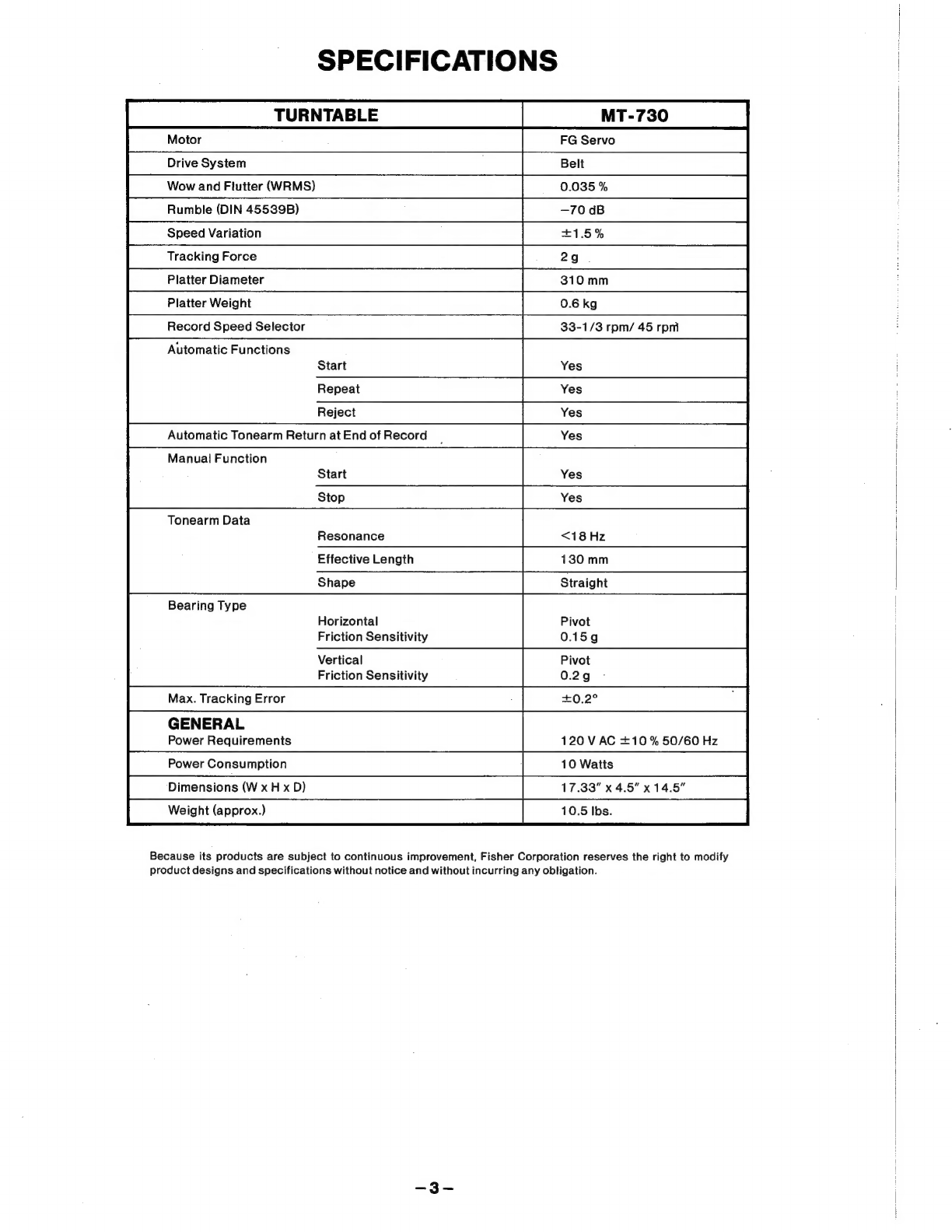
Specifications:
..csvesseleseehet
es
to
dks
ee
eee
gc
haw
new
sk
Some
bbe
ee
se
oes
3
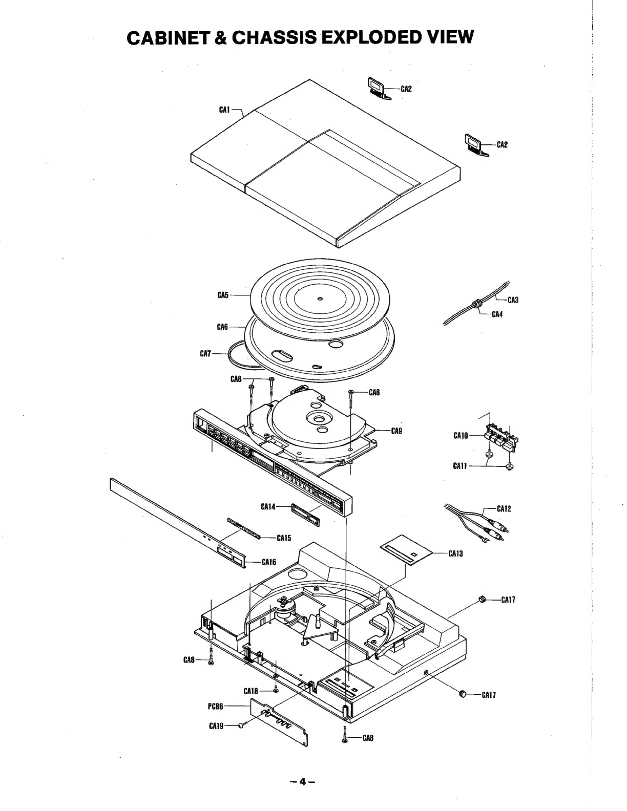
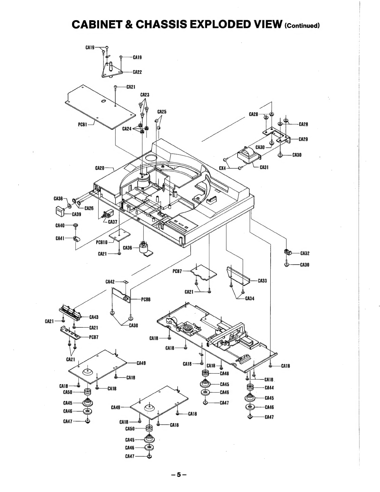
Cabinet
&
Chassis
Exploded
View
...........
0...
c
ccc
ccc
cece
cece
ene
eeeeeeceesneuees
4,5,6
Cabinet
&
Chassis
Parts
List
..........
0.0...
ccc
cece
cece
cece
ce
neve
eeeenseusueeeesecucues
7,8
Turntable
Adjustments
..............
0.0
cece
cece
cece cece cece
eee
e
eee
tateetesesueneneunene
9,10
Printed
Circuit
Board
(Bottom
View)
..............ccc
cece cece
sceeeeeesseeenes
11,12,13,14
P.C:
Board
Parts:list
ci
csicecesteca
ccaiscag
ce
oobens
eck
Seaied
agen
ss be
teeieeeeada
cee
oes
15,16
IC
Signal
Flow
&
Equivalent
Circuit
............
00...
ccc
cece
eee eee
ee
cee
see
euneuenees
17
Semiconductor
Lead
Identification
.............ccccesceccecseecececeseeceueeuaeeneeees
AB
Schematic
Diagram
:..
32k
dad
ds
weed
weedy
sew dee
eowiunlepeated
sovlceaenegaden
eae
19,20
Point
to
Point
Wiring
Diagram
.............
0c
ccc
cece
cece
cece
eee
ce
eeceeeenesucueueens
21,22
Caution
of
Usage
for
Motor
.............
ccc
cece
ccc
cece
cece
cece
eee
e
te
etnseeenneneuaenenans
23
Caution
of
Usage
for
ICO3
.....
ccc
cece
cece
cee
cece
ene
eeencuenseceeeneueaes
23
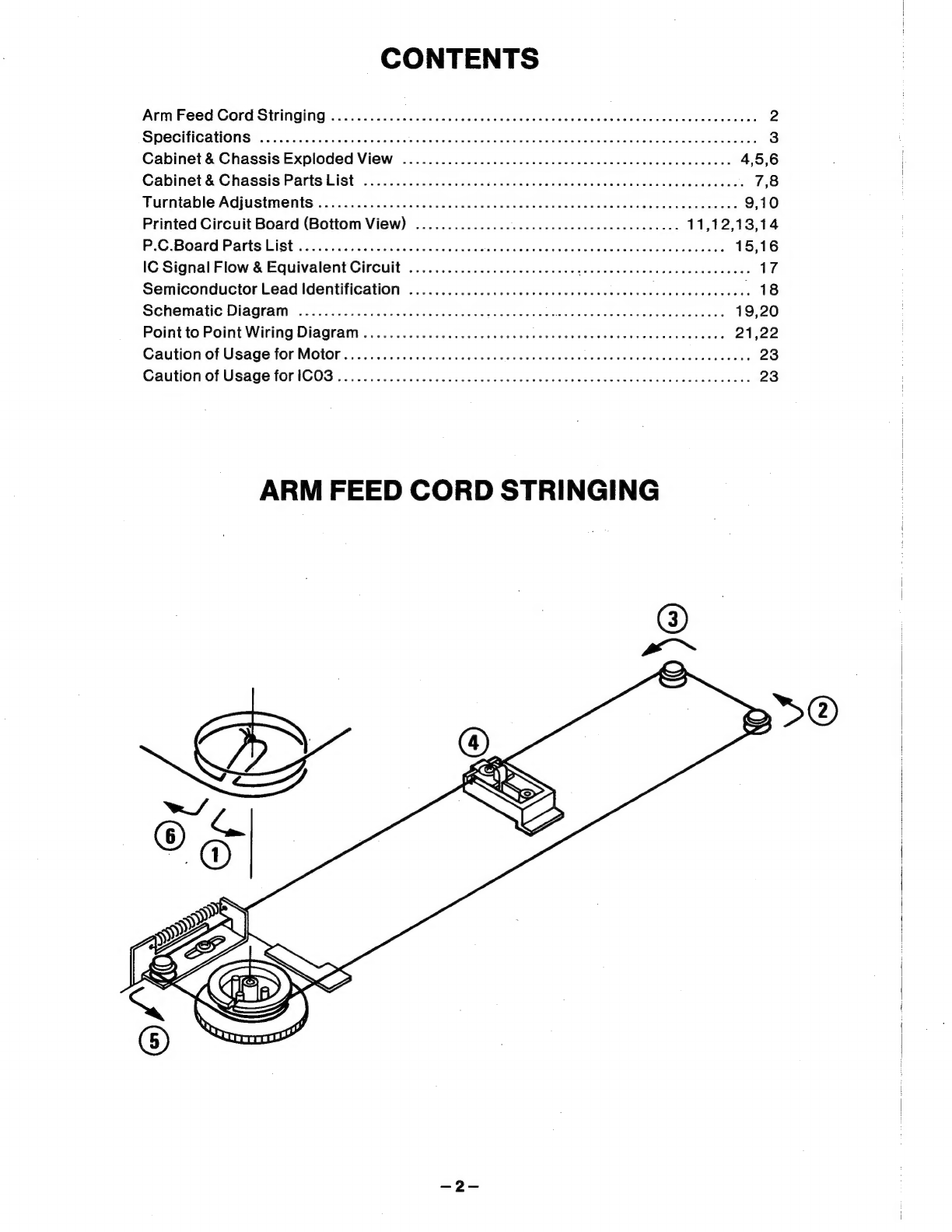
ARM
FEED
CORD
STRINGING