CONTENTS
Arm
Feed
Cord
Stringing
............
cece
cece
cece
eee
e
cece
cnet
e
ee
en
tent
ee
en
eneeeneneeenes
2
SpeCitiCavOnS-sicctiwkcicessncte
ca
dese
ue
lave
noore
vosdpe
vainseeabadeh
enero
bateee
eanuiaers
3
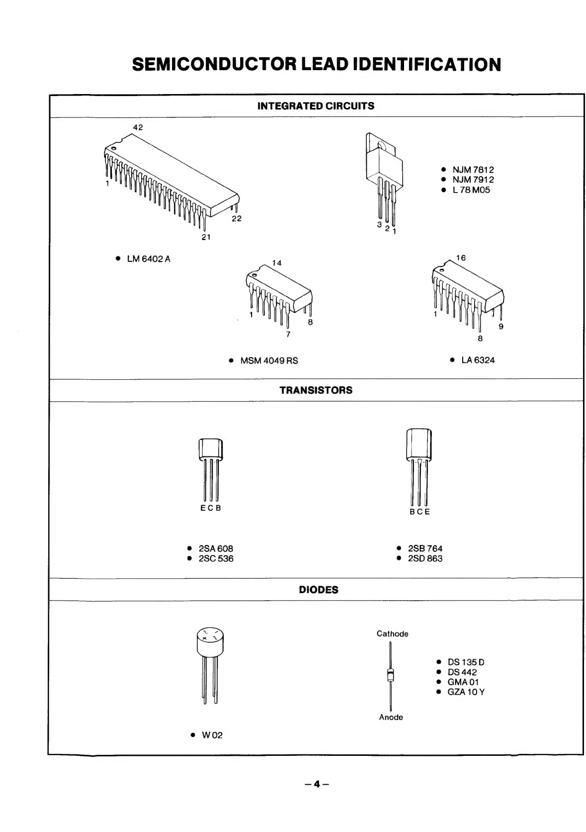
Semiconductor
Lead
identification
............
0...
ccc
cece
cece
eee
e
nee
e
eee
e
ee
eee
eens
4
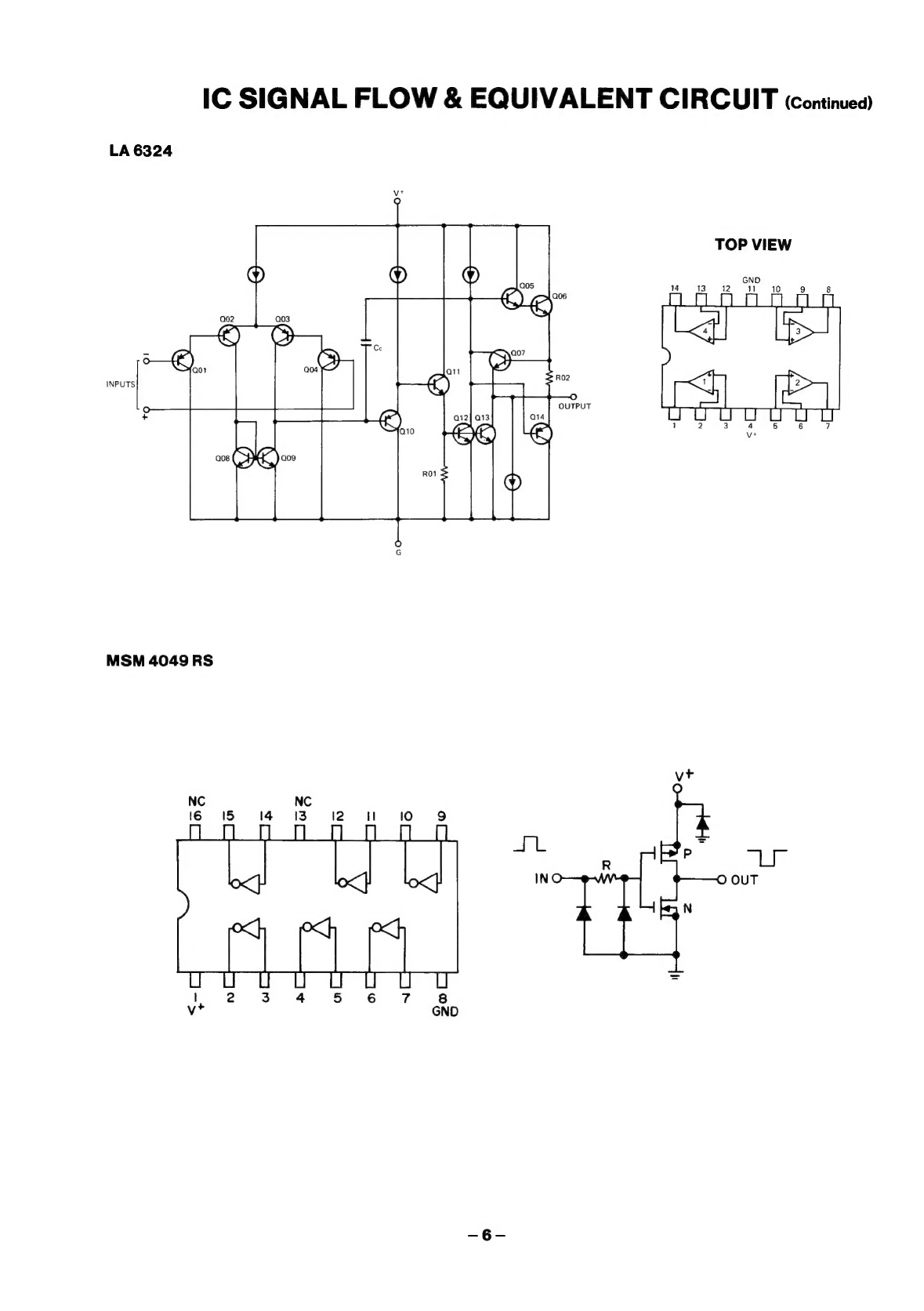
IC
Signal
Flow
&
Equivalent
Circuit
..........0....
ccc
ccc
cece
een
eens
5,6
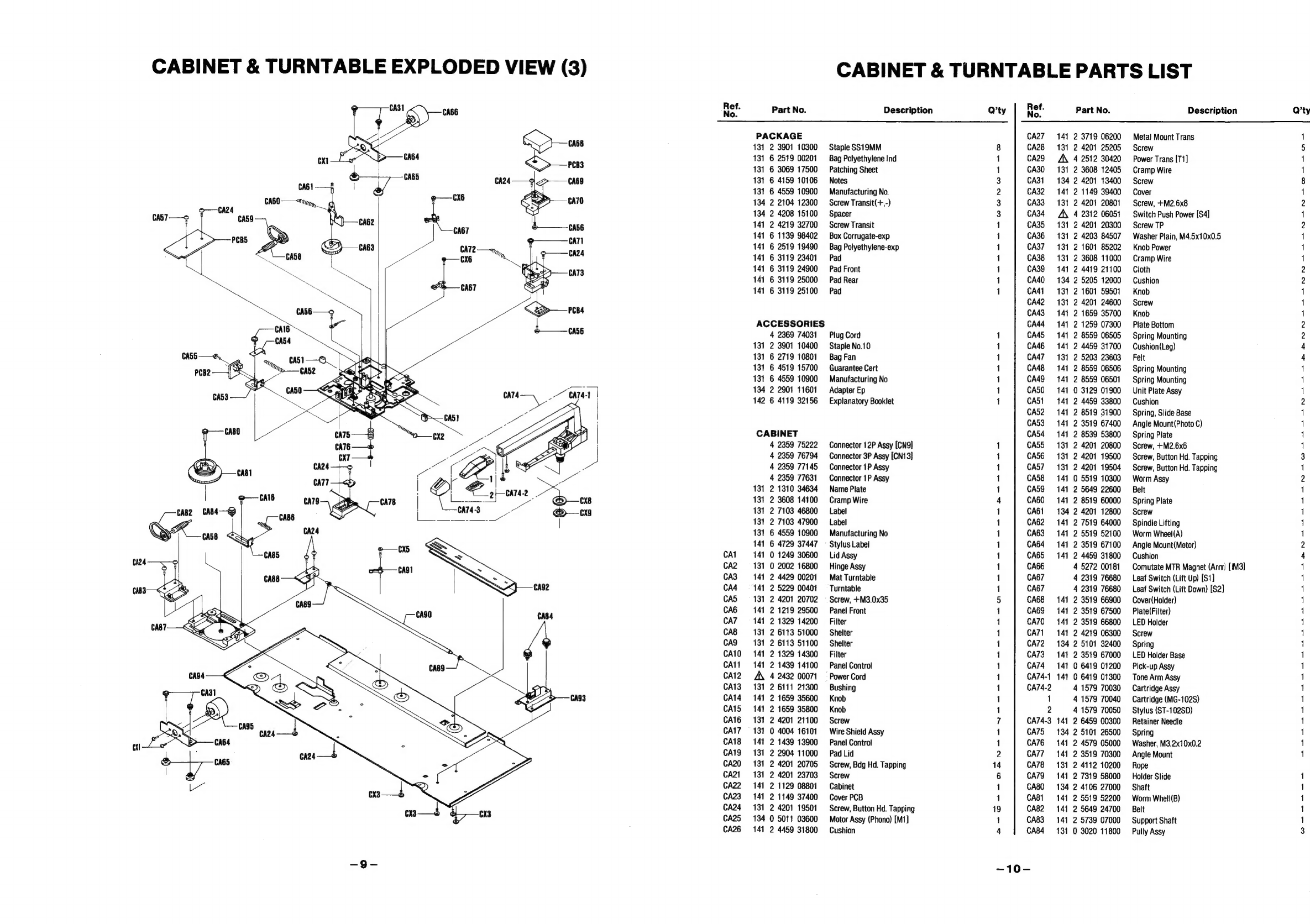
Cabinet
&
Turntable
Exploded
View
..............
0c
cece
cece cece
een
e
tee
eeeeeeenenes
7,8,9
Cabinet
&
Turntable
Parts
List
..............
0...
c
cece
cece
cece
eee
ene
eee
eeeeeeeeeee
10,11
Functional
Description
...............c
cee
cece
eee
e
ene
e
nee
e
eee
ener
enn
ene
en
eeeeee
12,13,14
Adjustment
Procedures
..........
0.
ccc
eee
ete
e
eee
e
erence
een
ene
n
en
ees
15,16,17
P.C.Board
Parts
List
............ccccccenccccccccncacacenccnesencusecurccscesusvecs
18,19,20
Printed
Circuit
Board
(Bottom
View)
...............c
cece
cece ence
ee
ee
21,22,23,24,25,26
Schematic
Diagram
.............:
ccc
cece
cece
cece
eee
ete
eee
en
eee
tere
e
ee ne
nena
27,28
Point
to
Point
Wiring
Diagram
.............
cc
cece
e
eee
eee
ee
n
eee
e
een
een
eee
e
es
29,30
Motor
Assy
Schematic
Diagram
...............
cece
cece
cece
eee
e
ete
e
eee
eee
ee
aee
31
Motor
Assy
P.C.Board
(Bottom
VieW)
...........
0c
cece
cece
cece
nnen
eee
eeeeeenneees
31
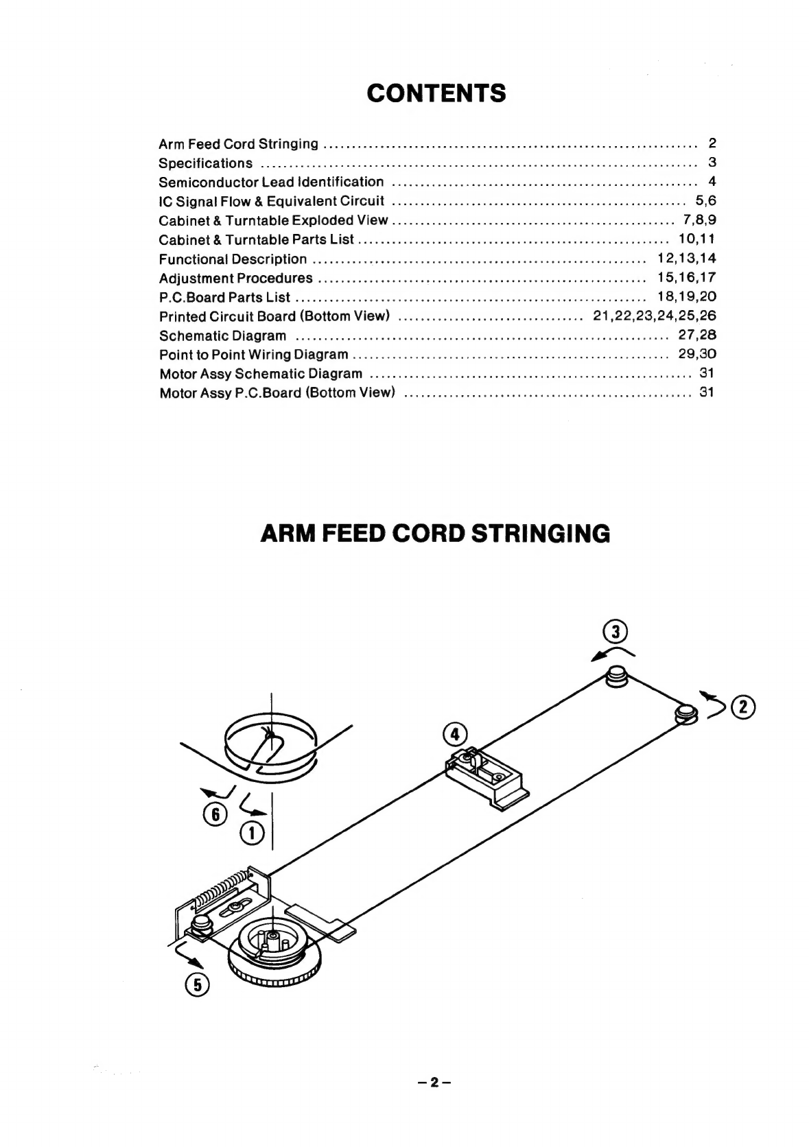
ARM
FEED
CORD
STRINGING