FitNord CYCLO 200R User manual

F
FI
IT
TN
NO
OR
RD
D
C
CY
YC
CL
LO
O
2
20
00
0R
R
R
RE
EC
CU
UM
MB
BE
EN
NT
T
OWNER’S MANUAL
IMPORTANT!
Please read all instructions carefully before using this product.
Retain this manual for future reference.
The specifications of this product may vary slightly from the illustrations and are subject to
change without notice.

- 1 -
Before You Start
Thank you for purchasing this Bike! For your safety and benefit, read this manual carefully before
using the machine.
Prior to assembly, remove components from the box and verify that all the listed parts are supplied.
Assembly instructions are described in the following steps and illustrations.
IMPORTANT SAFETY NOTICE
PRECAUTIONS
BE SURE TO READ THE ENTIRE MANUAL BEFORE YOU ASSEMBLE OR OPERATE YOUR MACHINE. IN
PARTICULAR, NOTE THE FOLLOWING SAFETY PRECAUTIONS:
1、Check all the screws, nuts and other connections before using the machine for the first time and ensure
that the trainer is safe to use.
2、Position the machine in a dry, level place and keep away from moisture and water.
3、Place a suitable base (e.g. rubber mat, wooden board etc.) beneath the machine in the area of assembly
to avoid dirt etc. getting under the machine.
4、Before training, remove all objects within a radius of 2 meters from the machine.
5、DO NOT use aggressive cleaning articles to clean the machine. Only use the supplied tools or suitable
tools of your own to assemble the machine or repair any parts of machine. Remove drops of sweat from
the machine immediately after finishing training.
6、Your health can be affected by incorrect or excessive training. Consult a doctor before beginning a
training program. He can define the maximum settings (Pulse. Watts. Duration of training etc.) to which
you may train yourself and can get precise information during training. This machine is not suitable for
therapeutic purposes.
7、Only train on the machine when it is working correctly. Use only original spare parts for any necessary
repairs.
8、Only one person at a time on the machine.
9、Wear training clothes and rubber sole shoes which are suitable for fitness training on the machine.
10、If you have a feeling of dizziness, sickness, or other abnormal symptoms, stop training and consult a
doctor as soon as possible.
11、Children and disabled persons should only use the machine in the presence of another adult who can
give aid and advice.
12、The machine’s power increases with speed. The machine is equipped with an adjustable knob that can
be used to adjust the resistance. Reduce the resistance by turning the knob towards stage 1. Increase
the resistance by turning the knob towards stage 8.
WARNING: BEFORE BEGINNING ANY EXERCISE PROGRAM, CONSULT YOUR PHYSICIAN. THIS IS
ESPECIALLY IMPORTANT FOR PERSONS WITH PRE-EXISTING HEALTH PROBLEMS. READ ALL
INSTRUCTIONS BEFORE USING ANY FITNESS EQUIPMENT.
SAVE THESE INSTRUCTIONS / Maximum user’s weight: 100kg

- 2 -
EXPLODED DIAGRAM

- 3 -
PARTS LIST
NO.
DESCRIPTION
Q’TY
NO.
DESCRIPTION
Q’TY
1
Main frame
1
31
Foam grip
2
2
Seat frame
1
32
Square end cap 38x38x1.5
2
3
Handlebar
1
33
Square end cap 80x40x2
2
4
Guide rail
1
34
Bushing
2
5
Handlebar post
1
35
Bracket
1
6
Front stabilizer
1
36
Saddle
1
7
Rear stabilizer
1
37
Backrest
1
8
Handle
1
38
Plug
2
9
Carriage bolt M8×L76
4
39
Round end cap
4
10
Carriage bolt M8×L45
2
40L/R
Crank
1pr
11
Acorn nut M8
6
41
Pulse wire
2
12
Arc washer Φ20×d8.5×R30
10
42
Extension pulse wire 1
1
13
Spring washer D8
16
43
Sensor wire
1
14
Allen screw M8×16
18
44
Computer
1
15
Washer D8×1.5×Φ16
17
45
Extension pulse wire 2
2
16
Axle spring washer D12
1
46
Flat washer
4
17
Axle spring washer D10
1
47
Square end cap 60×30×1.5
1
18
Eccentric gear
1
48
Cross tapping screw ST4.2x18
4
19
Eccentric shaft
1
49
Lifting handle
1
20
Small alloy bushing
1
50
Allen screw M8×75×L20
2
21
Big alloy bushing
1
51
Foam grip
1
22
Hex bolt M6×10
4
52
Tension wire
1
23
Tension controller
1
53
Plastic handle knob
1
24
Arc washer
1
54
Handlebar cover
1
25
Front end cap
2
55
Spacer
1
26
Rear end cap
2
56
Handlebar
1
27L/R
Pedal
1pr
57
Foam grip
2
28
Adjusting pad
1
58
Nut M10
1
29
Cross screw
1
59
Cross screw
4
30
Extension sensor wire
.1

- 4 -
ASSEMBLY INSTRUCTIONS
STEP 1:
1. Lock the Lifting handle (49) to the Rear stabilizer (7) with Allen screws (50), Spring
washers (13) and Arc washers (12).
2. Attach the Front stabilizer (6) and Rear stabilizers (7) to the Main frame (1) with Carriage
bolts (9), Spring washers (13), Arc washers (12) and Acorn nuts (11).
3. Attach the Adjusting pad (28) and Nut (58) to the Main frame (1).
STEP 2:
1. Attach the Pedals (27L/R) to the Cranks (40L/R) with a wrench.
Note: Both pedals are labeled L for left and R for right. To tighten, turn the Left pedal
counterclockwise and the Right pedal clockwise. Make sure the pedals are tightly attached
before exercising to prevent injuries or damage to the pedals.

- 5 -
STEP 3:
1. Connect Extension pulse wire 2 (45) with Extension pulse wire 1 (42).
2. Feed the Tension wire (52) through the hole in the Handlebar post (5)
3. Connect the Tension wire (52) with the Tension controller (23) as shown in picture A.
4. Attach the Tension controller (23) to the Handlebar post (5) with Cross screws (29) and
Arc washers (24).
5. Lock the Handlebar post (5) to the Main frame (1) with Allen screws (14), Spring
washers (13) and Arc washers (12).

- 6 -
STEP 4:
1. Attach the Handlebar (56) to the Handlebar post (5) with the Plastic handle knob (53),
Handlebar cover (54), Spacer (55) and Washer (15).
2. Connect the Extension pulse wire 2(45) and Extension sensor wire (30) with the
Computer (44) wires
3. Attach the Computer (44) to the Handlebar post (5) with Cross screws (59) and Flat
washers (46).

- 7 -
STEP 5:
1. Insert the Guide rail (4) into the Seat frame (2)
2. Attach the Guide rail (4) to the Main frame (1) with Allen screws (14), Spring washers
(13) and Washers (15).
- 8 -
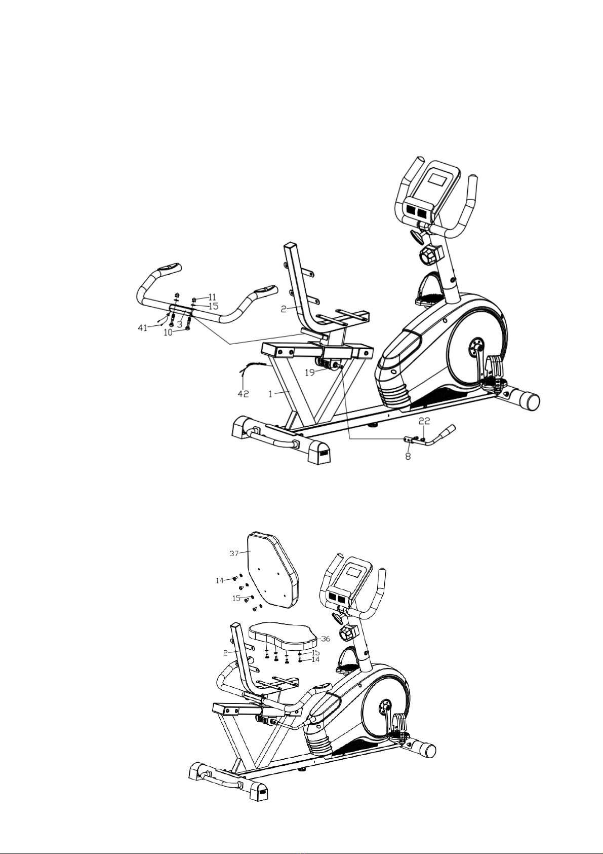
STEP 6:
1.Insert the Handle (8) into the Eccentric shaft (19) and lock with Hex bolts (22).
2.Insert the Handlebar (3) into the Seat frame (2) and lock with Carriage bolts (10),
Washers (15) and Acorn nuts (11).
3.Connect the Pulse wire (41) with the Extension pulse wire 1 (42).
STEP 7:
1. Lock the Backrest (37) to the Seat frame (2) with Allen screws (14) and Washers (15).
2. Lock the Saddle (36) to the Seat frame (2) with Allen screws (14) and Washers (15).
Table of contents
Other FitNord Exercise Bike manuals


 operating instructions")


