ESD CPCI-ETH2 User manual

CPCI-ETH2 Hardware Manual Rev. 1.0
CPCI-ETH2
CPCI-ETH2-FX
CPCI-ETH2-MX
10/100/1000BaseT- and/or 1000BASE-SX-
ETHERNET Interface for Com
p
actPCI
Hardware Manual
to Product I.2321.xx

CPCI-ETH2 Hardware Manual Rev. 1.0
Document file: I:\texte\Doku\MANUALS\CPCI\Eth2\English\CPCI-ETH2_10H.en9
Date of print: 05.07.2005
PCB version: CPCIET Rev. 1.0
Chan
g
es in the chapters
The changes in the user’s manual listed below affect changes in the hardware as well as changes in the
description of the facts only.
Chapter Chan
g
es versus previous version
- First version
Technical details are subject to change without notice.

CPCI-ETH2 Hardware Manual Rev. 1.0
N O T E
The information in this document has been carefully checked and is believed to be entirely reliable. esd
makes no warranty of any kind with regard to the material in this document, and assumes no
responsibility for any errors that may appear in this document. esd reserves the right to make changes
without notice to this, or any of its products, to improve reliability, performance or design.
esd assumes no responsibility for the use of any circuitry other than circuitry which is part of a product
of esd gmbh.
esd does not convey to the purchaser of the product described herein any license under the patent rights
of esd gmbh nor the rights of others.
esd electronic s
y
stem desi
g
n
g
mbh
Vahrenwalder Str. 207
30165 Hannover
Germany
Phone: +49-511-372 98-0
Fax: +49-511-372 98-68
E-mail: [email protected]
Internet: www.esd-electronics.com
USA / Canada:
esd electronics Inc.
12 Elm Street
Hatfield, MA 01038-0048
USA
Phone: +1-800-732-8006
Fax: +1-800-732-8093
E-mail: [email protected]
Internet: www.esd-electronics.us

CPCI-ETH2 Hardware Manual Rev. 1.0 1
Contents
1. Overview .................................................................... 3
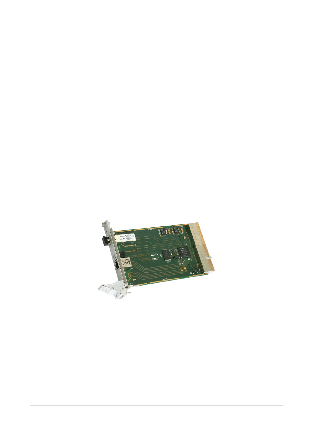
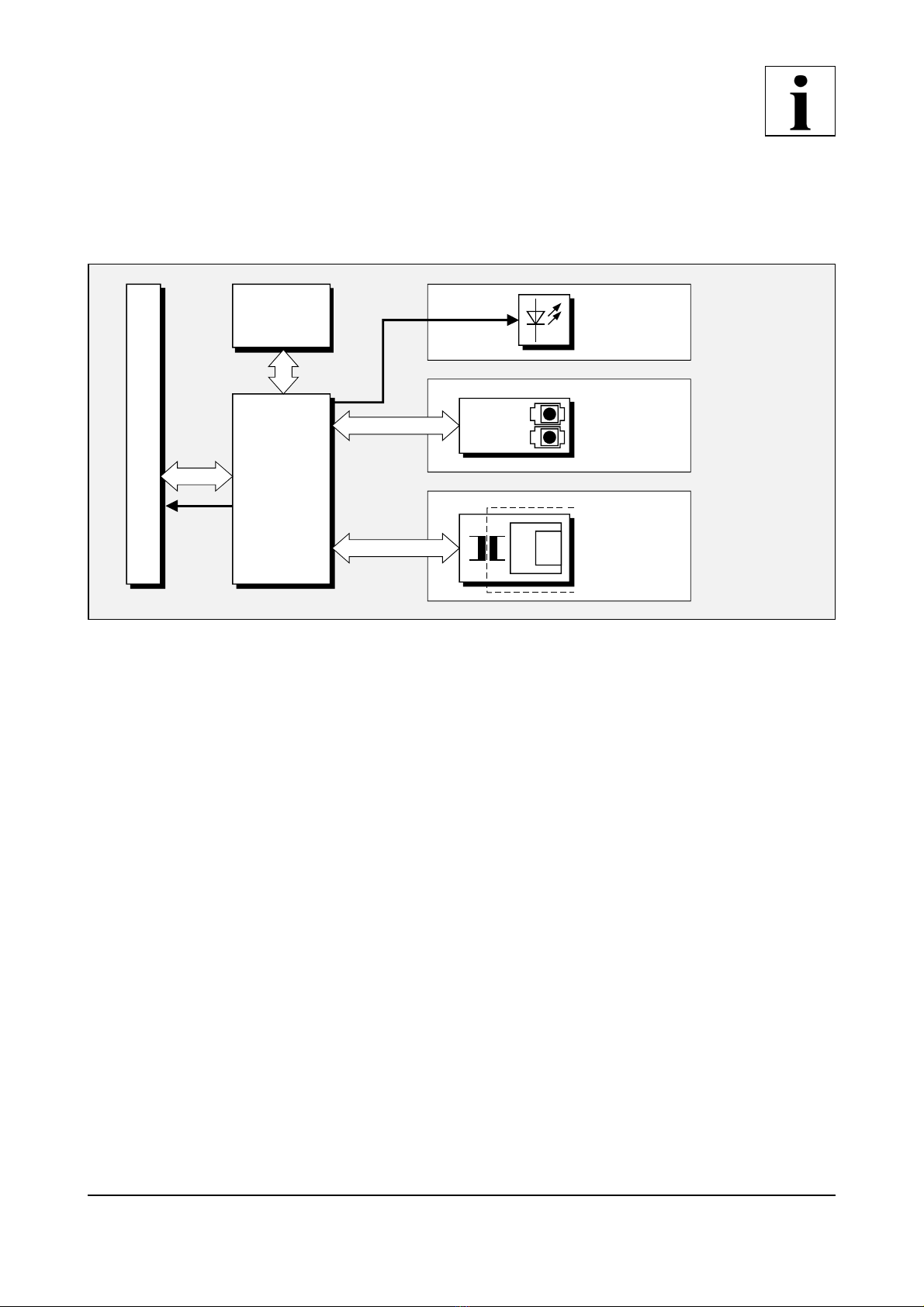
1.1 Description of the CPCI-ETH2-Module ......................................... 3
1.2 Summary of technical Data ................................................... 4
1.2.1 General Technical Data ................................................ 4
1.2.2 CompactPCI Bus ..................................................... 5
1.2.3 Ethernet Interface .................................................... 5
1.2.4 Fibre Optic Interface .................................................. 5
1.2.5 Software Support ..................................................... 6
1.2.6 Order Information .................................................... 7
2. Hardware Installation ......................................................... 8
3. Front Panel View with LED-Displa
y
............................................ 10
3.1 CPCI-ETH2: LEDs and Connectors in the Front Panel ............................ 10
3.2 CPCI-ETH2-MX: LEDs and Connectors in the Front Panel ........................ 11
3.3 CPCI-ETH2-FX: LEDs and Connectors in the Front Panel ......................... 12
4. Control .................................................................... 13
5. Connector Assi
g
nment ....................................................... 13
5.1 Ethernet 10/100/1000BaseT-Connection (X320, X420) ............................ 13
5.2 Ethernet 1000BASE-SX Connector (U310, U410) ................................ 14

CPCI-ETH2 Hardware Manual Rev. 1.02
This page is intentionally left blank.

Overview
CPCI-ETH2 Hardware Manual Rev. 1.0 3
IRQ
CompactPCI Connector
Electrical Isolation
Flash
EPROM
Ethernet Twisted Pair
10/100/1000BaseT
RJ45 Connector
4 LEDs per Channel
Fibre Optic
1000Base-SX
LC-Duplex Connector
Serial/Fibre-Optic
Converter
Intel 82546GB
Dual Port
Gigabit Ethernet
Controller
2x at CPCI-ETH2-FX
1x at CPCI-ETH2-MX
2x at CPCI-ETH2
1x at CPCI-ETH2-MX
2x at CPCI-ETH2
2x at CPCI-ETH2-FX
2x at CPCI-ETH2-MX
1. Overview
1.1 Description of the CPCI-ETH2-Module
Fi
g
. 1.1.1: Block diagram of the CPCI-ETH2 module
The CPCI-ETH2 is a CompactPCI board in Euro format.
The Intel 82546GB Gigabit controller provides two Gigabit ports on a single compact component.
Both Gigabit Ethernet ports can be equipped with either two 10/100/1000Base-T Ethernet interfaces,
two 1000Base-SX-Ethernet interfaces for optical fibres or mixed with one of each interface.
The CPCI-ETH2-module operates with standard Ethernet drivers.
The Ethernet interfaces for 10/100/1000Base-T-networks are easily accessible via RJ45-sockets in the
front panel. The interfaces are electrically isolated from the Ethernet controller.
The interfaces for the fibre optic connections are suitable for 1000Base-SX-nets (1000Base-LX on
request). The optical fibres are connected via LC-Duplex connectors in the front panel.
LEDs in the front panel indicate the status of the CPCI-ETH2.

Technical Data
CPCI-ETH2 Hardware Manual Rev. 1.0
4
1.2 Summar
y
of technical Data
1.2.1 General Technical Data
Ambient temperature 0...50°C
Humidity max. 90 %, non-condensing
Power supply
via CompactPCI bus,
nominal voltages: 5 V ± 5% and 3.3 V ± 5%
current consumption: tbd.
Connectors
X100 (132-pin post connector) -
CompactPCI-board connector P1
X101 (132-pin post connector) -
CompactPCI-board connector P2
X320 (8-pin RJ45-socket) - Ethernet Twisted Pair
10/100/100BaseT, (CPCI-ETH2, CPCI-ETH2-MX)
X420 (8-pin RJ45-socket) - Ethernet Twisted Pair
10/100/1000BaseT, (CPCI-ETH2)
U310 (HFBR-5911L/AL)- LC-Duplex connector
1000Base-SX, (CPCI-ETH2-FX)
U410 (HFBR-5911L/AL)- LC-Duplex connector
1000Base-SX, (CPCI-ETH2-FX, CPCI-ETH2-MX)
Dimensions 100 mm x 160 mm
Weight
CPCI-ETH2: 165 g
CPCI-ETH2-MX: 170g
CPCI-ETH2-FX: 175g

Technical Data
CPCI-ETH2 Hardware Manual Rev. 1.0 5
1.2.2 CompactPCI Bus
Host bus PCI-Bus according to PCI Local Bus Specification 2.3
PCI-data/ address bus 64 Bit
Controller Intel 82546GB
Interrupt Interrupt signal A, B
Board dimensions
according to CompactPCI-Specification, Rev. 1.0
Connectors
Connector coding Universal-Board (3.3 V or 5 V signalling voltage)
not keyed
1.2.3 Ethernet Interface
Number
CPCI-ETH2: 2
CPCI-ETH2-FX: -
CPCI-ETH2-MX: 1
Bit rate 10 Mbit/s, 100 Mbit/s, 1000 Mbit/s
Physical interface Twisted Pair (IEEE802.3) 10/100/1000BaseT
Electrical isolation via transformer integrated in the connector
Connector 8-pin RJ45-socket in the front panel
1.2.4 Fibre Optic Interface
Number
CPCI-ETH2: -
CPCI-ETH2-FX: 2
CPCI-ETH2-MX: 1
Bit rate 1000 Mbit/s
Physical interface IEEE802.3 Gigabit Ethernet (1.25Gbd) 1000Base-SX
(1000Base-LX on request)
Cable distance
275 m at 62.5 m Multimode fibre
550 m at 50 m Multimode fibre
(10 km on request for 1000Base-LX)
Connector LC-Duplex connector in the front panel

Technical Data
CPCI-ETH2 Hardware Manual Rev. 1.0
6
1.2.5 Software Support
The CPCI-ETH2-module operates with standard system drivers of Windows NT/2000, Linux,
VxWorks and QNX.

Technical Data
CPCI-ETH2 Hardware Manual Rev. 1.0 7
1.2.6 Order Information
Type Properties Order-No.
CPCI-ETH2 Dual 10/100/1000Base-T Ethernet I.2321.02
CPCI-ETH2-FX Dual Fibre Optic 1000BASE-SX Ethernet I.2321.04
CPCI-ETH2-MX Mixed 1000Base-T/1000BASE-SX Ethernet I.2321.06
CPCI-ETH2-MD User manual in English 1*) I.2321.20
CPCI-ETH2-ENG
Engineering Manual in English 2*)
Contents: Circuit diagrams, PCB top overlay drawing,
data sheets of significant components
I.2321.25
1*) If module and manual are ordered together, the manual is free of charge.
2*) This manual is liable for costs, please contact our support.

Installation
CPCI-ETH2 Hardware Manual Rev. 1.0
8
2. Hardware Installation
Warning!
The fibre optic interfaces are equipped with class 1 laser products.
Avoid direct eye exposure to the beam coming from the transmit port.
Caution!
Never carry out work when the power is turned on, this is highly dangerous!
Attention!
Electrostatic discharges may cause damage to electronic components. To avoid this,
please perform the following steps before you touch the module, in order to discharge
the static electricity from your body:
Switch off the power of your CompactPCI system, but leave it connected to the
mains.
Please touch the metal case of the system now to discharge yourself.
Furthermore, you should prevent your clothes from touching the CPCI module,
because your clothes might be electrostatically charged as well.
Installation:
1. Switch off your CompactPCI system and all connected peripheral devices (monitor, printer etc.).
2. Discharge your body as described above.
3. Disconnect the computer from mains.
4. Insert the CPCI-ETH2 module into a free CompactPCI bus slot.
5. Fix the CPCI-ETH2-module with the mounting screws in the front panel.
6. Connect the Ethernet cables (10/100/1000Base-T) to the RJ45-sockets (X320, X420) or if
applicable the Multimode fibre optic cables (1000Base-SX) to the LC-Duplex connectors (U310,
U410) in the front panels.

Installation
CPCI-ETH2 Hardware Manual Rev. 1.0 9
For working with the fibre optic cables, please, pay attention to the following instructions:
- The fibre may not be bend tightly. Do not make any kinks.
- Do not touch the tip of any optical connector.
- Make sure that the connectors fit tightly.
- Never look directly into the connectors or cables.
- Take care that no dust is introduced to the connector plugs.
7. Connect the computer to mains again.
8. Switch on the computer and the peripheral devices.
9. End of hardware installation.
10. Now, you can install the Gigabit Ethernet interface. Refer to the documentation of your operating
system.

Front panel view with LED-Displa
y
CPCI-ETH2 Hardware Manual Rev. 1.010
3. Front Panel View with LED-Dis
p
la
y
3.1 CPCI-ETH2: LEDs and Connectors in the Front Panel
Fi
g
. 3.1.1:
Position of the LEDs and
connectors of the CPCI-ETH2
LED Color Name Indication of the LED (LED on)
LED400A green L Link Status-Ethernet 2 (10/100/1000BaseT)
(Link to server or hub detected)
LED400B green A Activity, access of Ethernet 2 to the Dual Gigabit Ethernet controller 82546GB
LED400C green C Speed 100 (C) Status Ethernet 2, interface operates with a bit rate of 100 Mbit/s.
(at 10/1000 Mbit/s LED off).
LED400D green M Speed 1000 (M) Status Ethernet 2, interface operates with a bit rate of
1000 Mbit/s. (at 10/100 Mbit/s LED off).
LED300A green L Link Status-Ethernet 1 (10/100/1000BaseT)
(Link to server or hub detected)
LED300B green A Activity, access of Ethernet 1 to the Dual Gigabit Ethernet controller 82546GB
LED300C green C Speed 100 (C) Status Ethernet 1, interface operates with a bit rate of 100 Mbit/s.
(at 10/1000 Mbit/s LED off).
LED300D green M Speed 1000 (M) Status Ethernet 1, interface operates with a bit rate of
1000 Mbit/s. (at 10/100 Mbit/s LED off).
Table 3.1.1: Indication of the LEDs of CPCI-ETH2

Front panel view with LED-Displa
y
CPCI-ETH2 Hardware Manual Rev. 1.0 11
3.2 CPCI-ETH2-MX: LEDs and Connectors in the Front Panel
Fi
g
. 3.2.1:
Position of the LEDs and
connectors of the
CPCI-ETH2-MX
LED Color Name Indication of the LED (LED on)
LED400A green L Link Status Ethernet LWL2 (1000BASE-SX)
(Connection to server or hub detected)
LED400B green P Power, module in operation
LED400C green P Power, module in operation
LED400D green S Software Defined Pin LWL2, the indication of the LED must be defined via
software
LED300A green L Link Status Ethernet 1 (10/100/1000BaseT)
(Connection to server or hub detected)
LED300B green A Activity, access of Ethernet 1 to the Dual Gigabit Ethernet controller 82546GB
LED300C green C Speed 100 (C) Status Ethernet 1, interface operates with a bit rate of 100 MBit/s.
(at 10/1000 Mbit/s LED off).
LED300D green M Speed 1000 (M) Status Ethernet 1, interface operates with a bit rate of
1000 Mbit/s. (at 10/100 Mbit/s LED off).
Table 3.2.1: Indication of the LEDs of CPCI-ETH2-MX

Front panel view with LED-Displa
y
CPCI-ETH2 Hardware Manual Rev. 1.012
3.3 CPCI-ETH2-FX: LEDs and Connectors in the Front Panel
Fi
g
. 3.3.1:
Position of the LEDs
and connectors of the
CPCI-ETH2-FX
LED Color Name Indication of the LED (LED on)
LED400A green L Link Status Ethernet LWL 2 (1000BASE-SX)
(Connection to server or hub detected)
LED400B green P Power, module in operation
LED400C green P Power, module in operation
LED400D green S Software Defined Pin LWL 2, the indication of the LED must be defined via
software
LED300A green L Link Status Ethernet LWL 1 (1000BASE-SX)
(Connection to server or hub detected)
LED300B green P Power, module in operation
LED300C green P Power, module in operation
LED300D green S Software Defined Pin LWL 1, the indication of the LED must be defined via
software
Table 3.3.1: Indication of the LEDs

Connector Assi
g
nment
CPCI-ETH2 Hardware Manual Rev. 1.0 13
12345678
4. Control
The CPCI-ETH2 module operates with the standard system drivers of Windows 95/98, Windows
NT/2000, Linux, VxWorks and QNX. For software installation, please refer to the manual of the
operating system.
5. Connector Assi
g
nment
5.1 Ethernet 10/100/1000BaseT-Connection (X320, X420)
Connector type: RJ45-socket
Pin Position:
Cut-out for
fastening lever
Pin Assi
g
nment:
Pin Si
g
nal
1 MDI0+ (TxD+)
2 MDI0- (TxD-)
3 MDI1+ (RxD+)
4 MDI2+
5MDI2-
6 MDI1- (RxD-)
7MDI3+
8MDI3-
8-pin RJ45-socket

Connector Assi
g
nment
CPCI-ETH2 Hardware Manual Rev. 1.0
14
5.2 Ethernet 1000BASE-SX Connector (U310, U410)
Connector type: LC-Duplex connector, integrated in HFBR-5911L/AL
Warning!
The fibre optic interfaces are equipped with class 1 laser products.
Avoid direct eye exposure to the beam coming from the transmit port.
Fibre Position:
1
2
Assi
g
nment:
Fibre Si
g
nal
1TxD
2RxD
LC-Duplex connector
This manual suits for next models
2
Table of contents
Other ESD Recording Equipment manuals

ESD
ESD VME - ASIO16 User manual

ESD
ESD CPCI-CAN/400-4 User manual

ESD
ESD CAN-ISA/331 User manual

ESD
ESD CAN-CBX-THERMO User manual

ESD
ESD CPCI-CAN/400-2 User manual

ESD
ESD CAN-PCI/405 User manual

ESD
ESD ECS-XMC User manual

ESD
ESD CAN-CBM-CLOCK User manual

ESD
ESD CAN-PC104/200 Instruction manual

ESD
ESD C.2076.63 User manual

ESD
ESD ECS-PCIe/1100 User manual

ESD
ESD CPCI-CAN/331 Instruction manual

ESD
ESD PMC-CAN/331-3.3 Instruction manual

ESD
ESD CAN - PCC User manual

ESD
ESD CAN-PC104/331 Instruction manual

ESD
ESD CAN-PCI/266 User manual

ESD
ESD CAN-USB/3-FD User manual

ESD
ESD CPCI-USB-5 User manual

ESD
ESD CAN-PCI104/200 User manual

ESD
ESD CAN-USB/Micro User manual