manuals.online logo
Brands
  1. Home
  2. •
  3. Brands
  4. •
  5. FLAJZAR
  6. •
  7. Cell Phone
  8. •
  9. FLAJZAR GSM-DIN4 User manual

FLAJZAR GSM-DIN4 User manual

Popular Cell Phone manuals by other brands

Nokia 6700 classic user guide

Nokia

Nokia 6700 classic user guide

LG L34C user guide

LG

LG L34C user guide

Ericsson T60d manual

Ericsson

Ericsson T60d manual

Zte Score M user manual

Zte

Zte Score M user manual

Sony Xperia Z1 Compact Startup guide

Sony

Sony Xperia Z1 Compact Startup guide

AT AT-Q5 user manual

AT

AT AT-Q5 user manual

Vingtor ACM-M-A-V2 Installation/configuration

Vingtor

Vingtor ACM-M-A-V2 Installation/configuration

Olitech EasyFlip 2 Quick setup guide

Olitech

Olitech EasyFlip 2 Quick setup guide

Zte Atrium Z793C user manual

Zte

Zte Atrium Z793C user manual

Alcatel IDEAL manual

Alcatel

Alcatel IDEAL manual

Zte BLADE A520 quick start guide

Zte

Zte BLADE A520 quick start guide

switel M222 user manual

switel

switel M222 user manual

LG LG-P503 user guide

LG

LG LG-P503 user guide

LG F2410 user guide

LG

LG F2410 user guide

Argom E500 manual

Argom

Argom E500 manual

Hisense U30 user manual

Hisense

Hisense U30 user manual

Argom Tech E401 user manual

Argom Tech

Argom Tech E401 user manual

Nokia 3595 - Cell Phone - GSM Manual Del Usuario

Nokia

Nokia 3595 - Cell Phone - GSM Manual Del Usuario

manuals.online logo
manuals.online logoBrands
  • About & Mission
  • Contact us
  • Privacy Policy
  • Terms and Conditions

Copyright 2025 Manuals.Online. All Rights Reserved.

1|EN
GSM-DIN4
GSM communicator on DIN rail
INSTRUCTION
Last updating 26.5.2020
2|EN
Basic technical data
GSM-DIN4 communicator is a universal GSM device
for easy operation of any electrical appliances through
a common mobile phone.
The communicator contains four power outputs.
Three for the contact loading of 230V/5A and one
for the loading of 230V/16A.
It is possible to change their status by remote control
through SMS or by mere calling through (free of charge),
or by using the function of a timer or a thermostat with
connected external temperature sensor.
The communicator GSM-DIN4 is equipped with five logic
inputs which can be connected with any sensor.
Moreover, it has two measuring (analogue) inputs.
In the event of activation of these inputs, you will receive
the information SMS or the call on your mobile.
Supply voltage: this version allows 230V AC or 24V
AC/DC.
Outputs: 3x relay contacts with max. loading of
230V/5A and 1x relay contact with max. loading of
230V/16A (resistance load).
Inputs: 5x logic, separated by optical isolators, active
level +12V. The inputs are intended for connecting the
potential-free contacts!
2x analogue measuring inputs 0 - 12V DC
3|EN
Input for 4 temperature sensors with measuring range
from - 20°C to 125°C.
(Only the type recommended by the producer can be
connected. It is possible to buy it under the product
code TC530C2 or TC530C5)
Simple configuration through WiFi interface by means
of integrated web environment
Operating temperature: from -20°C to +45°C
GSM/GPRS QuadBand 850/900/1800/1900MHz
WiFi 802.11b/g/n (2.4GHz)
Dimensions: 90x71x62 mm (height x width x depth)
The device is intended for the dry environment. In the
event of external installation, use the box with
adequate covering.
Five universal inputs with the possibility of
configuration of the reaction to change, disconnection
or connection of the loop
Possibility of setting up the time of arrival and
departure
The inputs can be switched into the regime of
activated/deactivated inputs for the connection of a
keyboard, RFID and a receiver of remote control. Then
the device serves as a small security panel or
signalling device with optional activation/deactivation
through the access system. Information about the input
change can be sent to 10 phone numbers.
Functions and properties
4|EN
Each input can be named individually (text of sending
SMS)
If it is necessary to have the inputs permanently active
(in watching status), they can be switched into the
regime of 24-hour loop.
The input for the digital temperature sensors with
the possibility of automatic control of the input
(thermostat).
Information SMS in the event of exceeding the set
temperature or dropping the temperature under the set
limit.
Four power outputs - three with the contacts for
loading 230V/5A (resistance load) and one for
230V/16A (resistance load). Each output can have a
timer with a specific control order (e.g. SWITCH THE
HEATING ON, SWITCH THE HEATING OFF ...)
Status of the device can be checked any time by SMS
message.
GSM-DIN4 can be easily and quickly configured
through the well-arranged and intuitive web
environment which is accessible through the internal
WiFi net. The web interface enables you to carry out all
configurations easily, to download and install them into
and from the configuration files.
5|EN
Description of the teminal block
6|EN
Description of the terminals
01-+ contact of temperature sensors (supply No.
TC530Cx)
02-- contact of temperature sensors (supply No.
TC530Cx)
03- 12V DC for the analogue (measuring) inputs.
04- Analogue input A1
05- Analogue input A2
06- GND for the analogue (measuring) inputs
07- 12V DC for the logic inputs
08- Logic input IN1
09- Logic input IN2
10- Logic input IN3
11- Logic input IN4
12- Logic input IN5
13,14- Supply voltage of this version:230V AC or 24V
DC/AC.
15- 12V DC for supplying the sensors
16- GND for supplying the sensors
17- +contact for the back-up power supply (Supply No.
UPSZ)
18- - contact for the back-up power supply (Supply No.
UPSZ)
19- Common contact of relay outputs OUT1,2,3
20- Relay output OUT1 max. current 5A
21- Relay output OUT2 max. current 5A
22- Relay output OUT3 max. current 5A
23,24- Relay output OUT4 max. current 16A
7|EN
Description of connectors and slots
SD- Slot for microSD cards for saving the history (PUSH-
PUSH)
SIM- Slot for microSIM cards (PUSH-PUSH)
SMA- Connector for connecting GSM antenna
Description of DIP switch
DIP1
DIP2
DIP3
DIP4
Position
ON
DIN4
on
Automate
RUN
GSM
on
WiFi
AP
regime
Position
OFF
DIN4
off
Automate
STOP
GSM
off
WiFi
Client
regime
8|EN
Description of LED signalling
IN1- IN5
(green)
Green is off - the input in not connected
Green is on - the input is connected
POWER
(green)
Green is off - DIN4 is off
Green is on - DIN4 is on
RUN
(yellow)
Yellow is off - the automat is in the STOP
regime, evaluating loop is stopped; the
device does not evaluate sensors and
inputs. Yellow is on - automat is in the
RUN regime, the evaluating loop works,
the device evaluates sensors and inputs.
WIFI
(yellow)
Yellow is off - WiFi is off. Yellow is on -
WiFi is connected to AP or it transmits as
AP (according to DIP4 configuration).
Yellow flickers - WiFi is not connected to
AP (is not set or the configuration of the
net name and the net password is
incorrect)
GSM
(yellow)
Yellow is off - GSM module is off (DIP4
OFF)
Yellow flickers - GSM module is just
connecting to the net.
Yellow is on - GSM is connected to the net.
Yellow flickers shortly - indication of
receiving or sending SMS message.
OUT1 -
OUT4
(red)
Red is off - the output is not connected
Red is on - the output is connected
9|EN
Initial start-up
Connect terminals 13 and 14 to the power supply of
230V or 24V according to the device version.
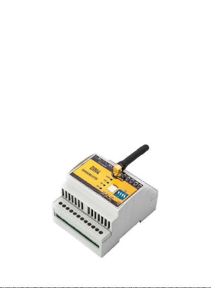
After switching the communicator GSM-DIN4 on, switch
over DIP1 to the position ON and the green LED diode
POWER will be on.
If the switch DIP3 OFF is off, insert the activated
microSIM card into the SIM slot while the PIN code
inquiry is off. Screw the GSM antenna in the
antenna SMA connector. Now it is possible to switch
on GSM module by switching DIP3 into the position
ON. Yellow LED diode of GSM will start flickering
and after successful connection yellow GSM LED will
be on permanently.
We recommend using the cards with flat-rate tariff
instead of prepaid re-chargeable cards. In the event
of insufficient credit on the card the device will be
out of service.
The program of the communicator contains the
evaluating loop which is controlled by the switch DIP2.
If DIP2 is in the position ON, the evaluating loop is in
RUN regime; the inputs and outputs are evaluated and
controlled according to the setting-up. If DIP2 is in OFF
position, the evaluating loop is stopped (STOP), the
inputs and outputs are neither evaluated nor controlled.
10|EN
Installation of GSM-DIN4 communicator
As the device is supplied from the network voltage of
230V, its installation should be carried out by a specialist
with appropriate qualification.
Caution: incorrect connection of sensors can cause
unreliable operation of the device or even its damage.
Recommended cable cross-section for the supply of
device: 2x1mm2, protected by fuse F 1A / 250V with high
interrupting capability.
Caution: Considering the insulation distance between the
terminals of 230V network voltage and the terminals of
output relays, it is permitted to connect to the relays only
appliances supplied by 230V AC.
The installation position is determined by the orientation
of the front plate (the side of device with supply input and
relay outputs downwards).
The device must be equipped with an easily accessible
disconnecting element (circuit breaker, switch)
If you use a delivered antenna, do not place any wires
nearby.
We recommend using an external antenna for enclosed
spaces or for the places with weak signal (under 40%).