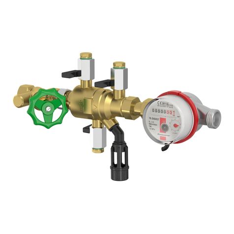
flamco Prescor IC Fill User manual

KP900722/V1.0/08-2020
www.flamcogroup.com/manuals
Prescor IC Fill
ENG
1. General
Application
The Prescor IC Fill Safety Group can be fitted to all kinds of domestic
hot water heaters with a capacity of 75 kW max. and 150 kW max. (in
accordance with European Standard EN 1488), such as electrical, gas or
indirectly fired boilers.
Min. / max. system temperature: 0 °C / 95 °C.
During firing, the volume of the water will increase and the pressure will
rise. The safety valve will open and the water will flow through the tundish
into the drain.
Safety
Fit the Prescor IC Fill in a position not susceptible to frost and easily ac-
cessible for maintenance purposes. Do not fit any stop valves between the
hot water unit and the safety group.
2. Installation
The following points are important for correct operation of the safety
group:
• Make sure installation is carried out by qualified personnel.
•Observe local legislation and guidelines.
•Carry out the installation only on a depressurised system (potable water
and heating).
•Install the safety group only aer the pipes have been thoroughly flushed
and tested (potable water and heating).
•The safety group can then be installed directly to the cold water supply
line of the boiler (potable water and heating).
•The potable water line should be connected according to the flow
direction indicated on the product (Fig. A).
•The Prescor IC Fill is equiped with a telescopic heating connection.
•Slide the heating connection carefully towards the conduit until these
are aligned.
•Always place the tundish vertically, pointing downwards (Fig. B).
•The drain pipe in accordance with European Standard EN 1488 min.
Ø 22 mm , can be connected directly to the tundish of the safety valve.
Commissioning
•Shut o all hot water taps aer bleeding the pipes.
•Open the Prescor Safety Group stop valve.
•Bleed air and water by liing the safety valve by turning the knob
anti-clockwise until no more air is released.
•To (re)top-up the heating system open the heating valve for filling til
reaching the right pressure (1.5 - 2.0 bar).
•Aer (re)topping-up always close the heating valve for filling. Deaerate
the heating system.
3. Maintenance and service
•The integrated non-return valve prevents water from flowing back into
the potable water line and should be checked annually.
•By closing the stop valve and to (carefully) open the plug (6mm hex key).
Water should not keep flowing out.
•The operation of the overflow must be checked visually.
•Aer prolonged shutdown of the boiler/ domestic hot water heaters it is
advisable to check operation of the product because of possible calcifica-
tion and replace if necessary.
•The Prescor IC Fill Safety Group is a safety product and it is therefore
recommended that it is replaced at least every 10 years.
•If the pressure in the pipe is likely to exceed 5.25 bar (525 kPa) by 8 bar or
3,75 bar (375 kPa) by 6 bar a pressure reducer must be fitted before the
safety group.
•The atmospheric breaker (tundish) must always remain unrestricted.
Draining the domestic hot water heater
•Shut o the Prescor IC Fill Safety Group stop valve.
•Open a hot water tap to allow air into the domestic hot water heater.
•Li the safety valve by turning the knob anti-clockwise until all of the hot
water has drained from the boiler.
4. Dismantling
Release the pressure from the system (potable water and heating).
Risk of burning! Hot water can flow out of the system. Remove the
product.
Environment
Abide by local regulations when disposing of the product.
DEU
1. Allgemein
Verwendung
Die Prescor IC Fill kann an Warmwasserbereiter aller Art mit einer Leistung
von max. 75 kW und max. 150 kW (nach EN 1488), wie elektrische, gas- oder
indirekt beheizte Geräte, montiert werden.
Anlagetemperatur min/max: 0 °C / 95 °C.
Beim Aufheizen nimmt das Wasservolumen zu, und der Druck steigt an. Das
Sicherheitsventil önet sich, woraufhin das Wasser durch den Trichter zum
Auslass strömt.
Sicherheit
Montieren Sie den Prescor IC Fill an einer frostsicheren und für Wartungs-ar-
beiten leicht zugänglichen Stelle. Bauen Sie keine Absperrventile zwischen
der Warmwasseranlage und der Sicherheitsgruppe ein.
2. Montage
Folgende Punkte sind zu beachten, damit die Sicherheitsgruppe
einwandfrei funktioniert:
•Die Montage darf nur durch qualifiziertes Fachpersonal erfolgen.
•Regionale Gesetze und Richtlinien sind einzuhalten.
•Die Montage darf nur in einem drucklosen System erfolgen (trinkwassersei-
tig und heizungseitig).
•Installieren Sie die Sicherheitsgruppe erst, nachdem die Rohrleitungen
gründlich durchgespült und abgedrückt wurden (trinkwasserseitig und
heizungseitig).
•Die Sicherheitsgruppe kann direkt an die Kaltwasser-Anschlussleitung des
Geräts montiert werden (trinkwasserseitig und heizungseitig).
•Die Trinkwasserleitung muss in der angegebenen Fließrichtung an das
Produkt angeschlossen werden (Abb. A).
•Der Prescor IC Fill ist mit einem ausziehbaren Heizungsanschluss ausge-
stattet. Damit kann eine flexibele Anschlussverbindung hergestellt werden.
•Der Trichter muss immer vertikal nach unten weisen (Abb. B).
•Die Ablassleitung nach EN 1488 min. Ø 22 mm, kann direkt an den Trichter
des Sicherheitsventils angeschlossen werden.
Inbetriebnahme
•Alle Warmwasser-Absperrventile schließen, nachdem die Leitungen
entlüet wurden.
•Absperrventil der Prescor Sicherheitsgruppe önen.
•Lu und Wasser abblasen bzw. ablassen, indem das Sicherheitsventil
durch Drehen des Knopfes nach links geönet wird, bis der Entleerungs-
vorgang beendet ist.
•Zur Nach-/Befüllung des Heizungssystems önen Sie das Heizungsventil
zur Nachspeisung bis der richtige Druck erreicht ist (1,5 - 2,0 bar)
•Nach der Nach-/Befüllung schließen / stellen Sie sicher, dass das Nach-
speiseventil geschlossen ist. Entlüen Sie das Heizungssystem.
3. Wartung und Service
•Das integrierte Rückschlagventil verhindert, dass Wasser in die Trinkwas-
serleitung zurückfließt. Es muss daher jedes Jahr kontrolliert werden.
• Indem das Absperrventil geschlossen und der Stutzen (vorsichtig) geönet
wird (mit einem 6-mm-Innensechskantschlüssel). Es darf kein Wasser
austreten.
•Die Funktion des Überlaufs muss einer Sichtprüfung unterzogen werden.
•Nach einem längeren Stillstand des Kessels/ Warmwasserbereiter wird eine
Funktionsprüfung des Produktes empfohlen, weil möglicherweise Verkal-
kung entstanden sein kann. Tauschen Sie das Produkt gegebenenfalls aus.
•Die Prescor IC ist ein Sicherheitsprodukt und es wird empfohlen es alle 10
Jahre auszutauschen.
•Wenn der Druck im Rohr wahrscheinlich 5,25 bar (525 kPa) mit 8 bar oder
3,75 bar (375 kPa) mit 6 bar übersteigt, muss ein Druckreduzierer vor der
Sicherheitsgruppe installiert werden.
•Die atmosphärische Unterbrechung (Ablaurichter) muß stets
uneingeschränkt frei bleiben.
Entleeren des Warmwasserbereiters
•Schließen Sie das Absperrventil der Prescor IC Fill Sicherheitsgruppe.
•Önen Sie den Warmwasserhahn, um Lu in den Warmwasserspeicher zu
lassen.
•Sicherheitsventil durch Drehen des Knopfes nach links önen, bis das
gesamte Wasser aus dem Gerät geflossen ist.
4. Demontage
Das System drucklos machen (trinkwasserseitig und heizungseitig).
Vorsicht: Verbrühungsgefahr! Es kann heißes Wasser aus dem
System fließen. Das Produkt entfernen
.Umwelt
Bei der Entsorgung des Produkts die örtlichen Vorschrien beach-
ten.
Ø 22 mm Ø 15 mm
Ø 15 mm
AAA
B

www.flamcogroup.com/manuals
NLD
1. Algemeen
Toepassing
De Prescor IC Fill Inlaatcombinatie kan worden gemonteerd op
alle soorten warmwaterbereiders met een capaciteit van maximaal 75
kW en maximaal 150 kW (volgens EN 1488) zoals elektrische, gas of indirect
gestookte toestellen.
Min. / max. systeemtemperatuur: 0 °C / 95 °C.
Tijdens het opwarmen ontstaat een volumevermeerdering van het water
en de druk stijgt. Het overstortventiel gaat open en het water stroomt dan
via de trechter naar de afvoer.
Veiligheid
Installeer de Prescor IC Fill inlaatcombinatie in een vorstvrije locatie en
op een plek die goed toegankelijk is voor onderhoud. Tussen het toestel en
de inlaatcombinatie mogen geen afsluiters geplaatst worden.
2. Installatie
De volgende punten zijn van belang voor een correcte werking van
de inlaatcombinatie:
•Laat de installatie uitsluitend door gekwalificeerd personeel uitvoeren.
•Houdt u zich aan de lokale regelgeving en richtlijnen.
•Voer de installatie uitsluitend uit op een drukloos systeem (zowel
sanitair als CV).
•Installeer de inlaatcombinatie pas nadat de leidingen grondig zijn
doorgespoeld en afgeperst (zowel sanitair als CV).
•De inlaatcombinatie kan direct op de koudwateraanvoerleiding
aanlsuiting van het toestel worden gemonteerd (zowel sanitair als CV).
•De drinkwaterleiding dient volgens de aangegeven stroomrichting op
het product te worden aangesloten (afb. A).
•Voor de Prescor IC Fill is de cv aansluiting telescopisch ontworpen.
•Schuif de cv aansluiting voorzichtig naar de gewenste leiding tot dat
deze in één lijn liggen.
•De trechter altijd verticaal naar beneden plaatsen (afb. B).
•De afvoerleiding volgens EN-1488 min. Ø22 mm kan direct op de trechter
van het overstortventiel.
Ingebruikname
•Alle warmwaterkranen sluiten na het ontluchten van de leidingen.
•Afsluitkraan van de inlaatcombinatie aan de sanitair zijde openen.
•Lucht en water aflaten door het overstortventiel te lichten door de knop
naar links te draaien tot er geen lucht meer wordt afgevoerd.
•Voor het (bij)vullen van de cv-installatie draai de cv-vulafsluiter open tot
het bereiken van de juiste druk (1,5 - 2,0 bar).
•Na (bij)vullen de cv-vulafsluiter altijd sluiten. CV-installatie ontluchten.
3. Onderhoud en service
•De ingebouwde keerkleppen verhindert terugstromen van water in de
drinkwaterleiding en dient jaarlijks te worden gecontroleerd.
•Door het sluiten van de afsluiters en het (voorzichtig) openen van het
controlestopje van de keerklep (inbus 6 mm). Er mag geen water uit
blijven stromen.
•De werking van de overstort dient visueel gecontroleerd te worden.
•Na langdurig stilstand van de ketel/warmwaterbereider wordt geadviseerd
het product te controleren op werking i.v.m. kalkafzetting en eventueel te
vervangen.
•Prescor IC Fill inlaatcombinatie is een veiligheidsproduct daarom raden
wij aan deze binnen 10 jaar te vervangen.
•Als de leidingdruk hoger is dan 5,25 bar (525 kPa) bij 8 bar of 3,75 bar (375
kPa) bij 6 bar moet voor de inlaatcombinatie een drukreduceerventiel
geplaatst worden.
•De atmosferische onderbreking (trechter) moet altijd vrij blijven.
Aappen van de warmwaterbereider
•Afsluitkraan van de Prescor IC Fill inlaatcombinatie sluiten.
•Een warmwaterkraan openen om lucht in de warmwaterbereider te
laten lopen.
•Overstortventiel lichten door knop links te draaien tot al het water uit
het toestel is gelopen.
4. Demontage
Maak het systeem drukloos (zowel sanitair als CV). Er is gevaar voor
verbranding! Er kan heet water uit het systeem stromen.
Verwijder het product.
Milieu
Houdt u zich aan de lokale wetgeving wanneer het product wordt
afgevoerd.
Ø 22 mm Ø 15 mm
Ø 15 mm
AAA
B
Other flamco Control Unit manuals

