flamco Meibes A1CX Series Manual
GB
Technical information for installation and operation
Meibes Heat Interface Unit (HIU) A1CX Series
Installation in conjunction with a pre-plumbed unvented cylinder.
Standard Unit 20 kW, High Pressure Unit 20 kW and 30 kW

2
1. Safety instructions 3
2. Introduction 5
2.1 Product Usage 5
2.2 Unit Layout 5
2.3 Hydraulic Layout 6
2.4 Facts and Figures 7
3. Installation 8
3.1 Preparation 8
3.2 Positioning 8
3.3 Fitting 8
3.4 Connecting 8
3.4.1 Hydraulic Primary Circuit 8
3.4.2 Hydraulic Secondary Circuit 9
3.5 Electrical Connections 9
3.5.1 Electrical Diagram (for wiring centre fitted at the pre-plumbed unvented cylinder) 9
3.5.2 HIU - Heating Circuit 9
4. Service 10
4.1 Commissioning 10
4.2 Pressure Test 10
4.3 Flushing / Corrosion prevention 10
4.4 Service Check List 11
5. Heat Meter 12
6. Appendix A 13
7. Appendix B 16
8. Appendix C 17
9. Appendix D - Spare Parts 21
Contents

3
Please follow these safety instructions faithfully to eliminate hazards, personal injury and material damage.
Target group
These instructions are intended exclusively for authorised trained experts. Only trained experts or installers authorised
by the respective competent utility company are permitted to work on the heating system, the domestic water, gas and
electric circuits.
Regulations
When carrying out work, you must comply with:
• The statutory accident prevention regulations,
• The statutory environmental protection regulations,
• The pertinent safety requirements of DIN, EN, DVGW, TRGI and TRF
• ÖNORM, EN, ÖVGW-TR Gas, ÖVGW-TRF and ÖVE
• SEV, SUVA, SVGW, SVTI, SWKI and VKF
• and all new and regionally applicable regulations and standards
Instructions for working on the system and system parameters
• Disconnect the system from the mains and monitor it to ensure that no voltage is being supplied (e.g. at the
separate cut-out or a main switch).
• Secure the system against being restarted.
The unit may only be installed in:
–Dry and not potentially explosive environments
–Enclosed rooms with temperatures of 5-50°C (not condensing)
• The devices must be installed in enclosed, frost-free spaces
• Observe the safety areas in accordance with 60529 when designing and installing the system
• Device protection code in accordance with EN 60520 IP42
Note:
The device is installed inside a building in an upright position on the wall, in a convenient location with suicient frost
protection.
Potential equalisation or protective earthing in accordance with VDE:
The HIU must be protected by potential equalisation or protective earthing according to the applicable
regulations!
1. Safety instructions

4
This unit must be installed, commissioned and inspected/serviced qualified technical personnel in accordance with
national regulations and/or relevant local requirements.
The mains electrical supply must be isolated before making any connections. Electrical
work must comply with regulations BS7671. Ensure the power supply is isolated when
working on any electrical components in the HIU. All installation and system work must
comply with the relevant building regulations.
Please be aware that the unit weighs approximately 15 kg, and as such should be handled
in accordance with health and safety guidelines and regulations. The unit should be
attached to a structurally sound wall capable of bearing the weight of the unit.
Water temperatures higher than 50°C may cause severe burns. Components within the
unit may be hot, and care should be taken to avoid burns and scalds when installing,
commissioning or inspecting/servicing the unit.
Any unauthorised alterations on the unit or tampering with it in any way will void the warranty and certificates.
1. Safety instructions
5
Heat Interface Units (HIU) supply space heating and domestic hot water to an apartment or house. They are connected
on the primary side to a heat network which supplies energy in the form of hot water. The secondary side of the unit
supplies the house or the apartment. The unit is fully factory assembled and contains all necessary hydraulic and electrical
components. It is designed to be installed in conjunction with a pre-plumbed unvented cylinder.
2.1 Product Usage
This product is to be installed by trained installers only! Please follow the safety instructions as well as all applicable
technical regulations. These instructions are aimed exclusively at trained installers and service technicians. Electrical work
may only be carried out by qualified electricians.
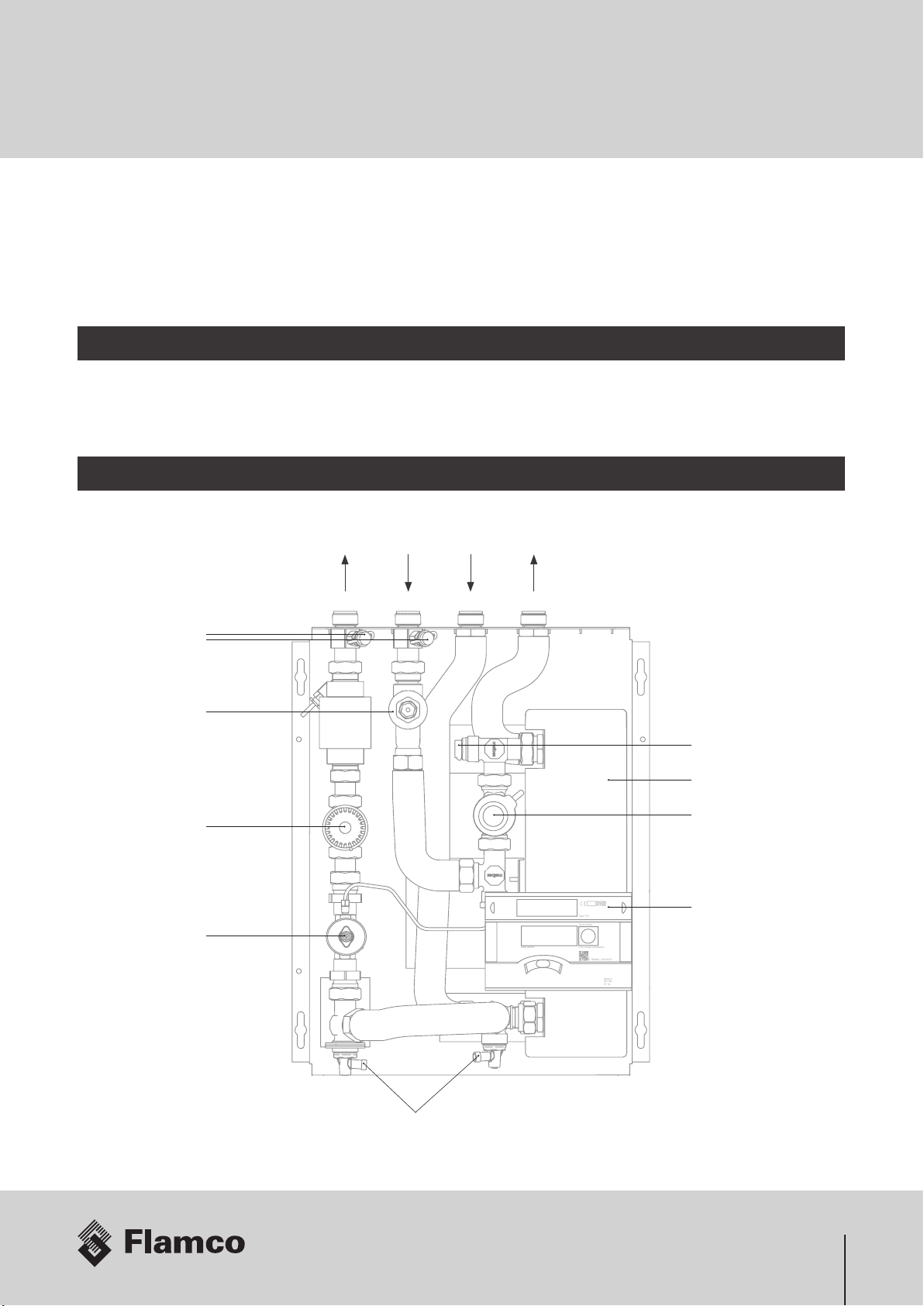
2.2 Unit Layout
Plate heat exchanger
Display Heat meter
Primary zone valve
Bleed points
Bleed points
Dierential pressure
control valve (DPCV)
Return Temperature
Limiter
Strainer
Test
points
SecondaryPrimary
2. Introduction
6 RAM40 1234 5678
Heat Meter
Quick Mode
Type 775
0102
LCD Loop3: Installation
Class 2
E2 / M2
IP 54

6
2.3 Hydraulic Layout
Diagram Parts Description
1. Test points
2. Strainer
3. Spool piece for heat
meter 3/4“x110mm
(removable)
4. Dierential pressure
control valve DPCV
(Balancer)
5. Zone valve
6. Plate heat exchanger
7. Bleed points
8. 3/4“ isolation ball valves
(not illustrated) Spool
piece for solenoid
valve 3/4“x110mm
(removable)
9. Return temperature
limiting valve (RTL).
Factory locked to 40°C
(Standard Unit), to 60°C
(High Pressure Unit).
Connections
A. Primary Flow
B. Primary Return
C. Secondary Flow
D. Secondary Return
370mm
465mm
1
3
4
5
6
3
7
7
2
9
AB CD
2. Introduction
6 RAM40 1234 5678
Heat Meter
Quick Mode
Type775
0102
LCD Loop3: Installation
Class 2
E2 / M2
IP 54
3
T
M
∑
1
1
27
77
9
6
4
A
B
C
D
5

7
2.4 Facts and Figures
Description Type District heating station to be installed in conjunction with a pre-plumbed unvented cylinder
Mounting Wall mounted with top or bottom connections
Size including case 400 x 180 x 500 mm (WxDxH)
Heating System 2 pipe flow
Construction Pipework Fully insulated flexible stainless steel pipe with brass fittings
Plate heat exchanger Fully insulated stainless steel
Casing White powder coated sheet steel cover with viewing window for the heat meter
Primary Fluid Low pressure hot water
Secondary Fluid Low pressure hot water
20kW Standard Unit 20 and 30kW High Pressure Unit
Duty (primary) Heat Transfer Capacity (P1; q1) 20 kW @ 30K ∆T (550 l/h) 20 kW @ 30K ∆T (550 l/h)
32 kW @ 30K ∆T (900 l/h)
Fluid Temperature flow (t11) 70°C (95º Max) 70°C (95º Max)
Fluid Temperature return (t12) - design (max.
temp. depends on RTL setting)
40°C 60°C
Pressure Primary max. pressure 6 bar 10 bar
Max. primary dierential pressure (∆p1) Depending to lowest value of components
Secondary max. pressure 6 bar 10 bar
Fittings
Primary side
Zone Valve Fitted with electrical actuator head, max.
dierential pressure 100 kPa (kvs=1.85)
Fitted with electrical actuator head, max.
dierential pressure 700 kPa (kvs=1.6)
Return Temperature Limiter 20 ... 65°C (Factory set fixed to 40°C), max. dp
= 150 kPa
25 … 70°C, (Factory set fixed to 60°C) max. dp
= 600 kPa
Strainer On primary flow
Test points Binder style test points
Sensor Pocket Primary Flow temperature sensor for heat meter
Heat Meter Rossweiner “HeatSonic“ M-Bus heat meter with permanent display. Battery or main power
available.
Dierential Pressure Control Valve (DPCV) Factory set (at 40 kPa), max. dp = 40 kPa 20 kW: at 13,5 kPa, max. 25 kPa
30 kW: at 40 kPa, max. dp = 40 kPa
Air Vents Manual
Connections All external connections 3/4” female ball valves 4x (not illustrated); optional “First Fix Rail” with or without flushing bypass
2. Introduction
Δp2
Δp1
t12
t11 t22
t21
q1q2
DH
∆p
q
t
P
= District Heating
= Differential Pressure (kPa)
= Flow Rate (l/s)
= Temperature (ºC)
= Power (kW)
Secondary
Primary (DH)
P2
P1
8
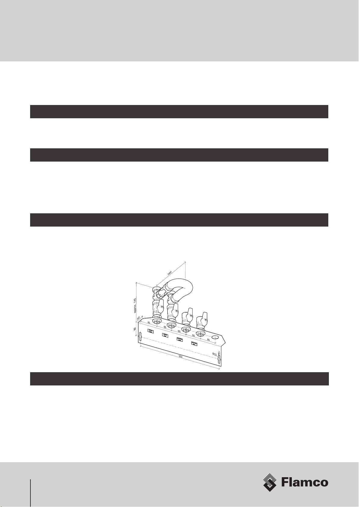
3.4 Connecting
All pipe connections are made to the isolating ball valves. These valves have standard 3⁄4” female BSP connections. Ensure
that the pipe material and size suits the system M&E specification. A safety pipe is part of pre-plumbed unvented cylinder
installation.
45 65 65 65 65
50
60
352
approx. 140
160
7
Ø12
The HIU must be installed inside a building. The location of the unit must be insulated against frost and easily accessible.
3.1 Preparation
Unpack the unit and read the installation manual to fully understand how the HIU is going to be fitted and connected.
Identify all hydraulic and electrical connections.
3.2 Positioning
The HIU needs to be fitted to a wall in an upright position with either isolating valves at the top or alternatively at the
bottom. The wall needs to be strong enough to support the unit. If the wall is of drywall construction make sure that there
is a supporting board (e.g. 18mm ply wood) installed to the supporting structure, which is strong enough to hold the unit.
While positioning the unit on the wall make sure that there is suicient space to run pipes and cables along the sides if
needed and leave suicient space underneath or above to connect the pipes to the isolating ball valves.
3.3 Fitting
The unit must be securely fitted using appropriate sized fittings. Ensure that the unit is mounted in an upright position. Fit
the First Fix Rail (FFR) to the wall using appropriate sized fittings as shown below. The external connections can be made
once the FFR is secured to the wall. The HIU can be hung at the FFR by sliding it onto the hanging points at any time but
must be secured to the structure using the 4 key hole shaped fixing points in the base plate of the unit.
3. Installation

9
3.5.2 HIU - Heating Circuit
The HIU has one 2-core cable which needs to be wired into the heating control. Connect the brown wire to the switched
live (call for heat) and the blue wire to neutral. No other wiring is required. If a prepayment meter is to be fitted refer to the
separate wiring diagram for the prepayment unit.
3.5.1 Electrical Diagram (for wiring centre fitted at the pre-plumbed unvented cylinder)
WIRING DIAGRAM 2 PORT ZONE VALVE (S-PLAN)
Key:
W=White, G=Grey,Bl=Blue,O =
Orange, G/Y = Green/Yellow, Br
= Brown, L = Live, N = Neutral,
C = Common Terminal, SW =
Switched Live, MV = Actuator
head of the primary zone valve
within the HIU
Note:
The mains supply for boiler
and programmer must be
taken from the “Wiring Centre”.
Br G
12 3
Bl
2 PORT (HTG) 2 PORT (DHW)CUTOUT (COMBINED) STAT
WIRING CENTRE
5A SUPPLY
ROOM STAT PROGRAMMER
BOILER
OC
1
1
2
2
LN
3
3
4
4
1234 LN SL
HTG
ON
DHW
ON
DHW
OFF
MV
BlBr
L
L PUMP
N
N
2
3
2
5
5
6
6
7
7
8
8
9
9
10
10
2C21
G YBr G
12 3
Bl O G Y
3.4.2 Hydraulic Secondary Circuit
There are 2 connections (flow and return) which need to be connected to the pre-plumbed unvented cylinder in the
apartment or house.
3.5 Electrical Connections
All wiring within the HIU must be supplied
from the same electrical circuit as the
controls for the heating system. This circuit
needs to be protected by a 5A fuse. The only
necessary connection within the HIU is the
2-core cable from the actuator head of the
motorised valve (MV) - see chapter “HIU
Heating Circuit”.
3. Installation
Blue Brown
Actuator
Head
Heat
Interface Unit
Wiring Centre of
Pre-Plumbed Cylinder
Fuse/Switch
Channel: Hot Water N
Boiler Call
230V
~
PE N
L
Room Thermostat
Channel: Space Heating
10
4.2 Pressure Test
The HIU and the installation must be pressure tested with 1.3 times the intended working pressure of the system (Refer M&E
specifications). If there are no leaks, the installation needs to be flushed. Both independent hydraulic systems need to be
tested in accordance to its own pressure rating. Please refer to the HIU specification.
4.3 Flushing/Corrosion prevention
All pipework that is to be connected to the units must be thoroughly cleaned and flushed out before the final connections
are made to the heat exchangers. Any debris or flux that could collect in the narrow channels of the heat exchangers will
be diicult to remove once they are installed. Remaining debris and flux could cause serious corrosion problems, as well
as restricting flow and reducing the eiciency of the units. Where soldered joints are used, it is preferable to employ fluxes
that are water miscible and do not contain chlorides (e.g. zinc or ammonium chloride), as these compounds are known
to be aggressive to stainless steel. It is also important to ensure that, where pipework installations are sterilised using
chemicals containing chlorine, safe levels are never exceeded if premature pitting corrosion is to be avoided. Any treatment
or cleaning should only be carried out by competent organisations that have the experience and technical resources to
monitor the installation during the chemical treatment process. Similarly, subsequent maintenance and water treatment
must follow accepted and approved practice.
For further guidance on water quality and treatment please refer to Appendix C.
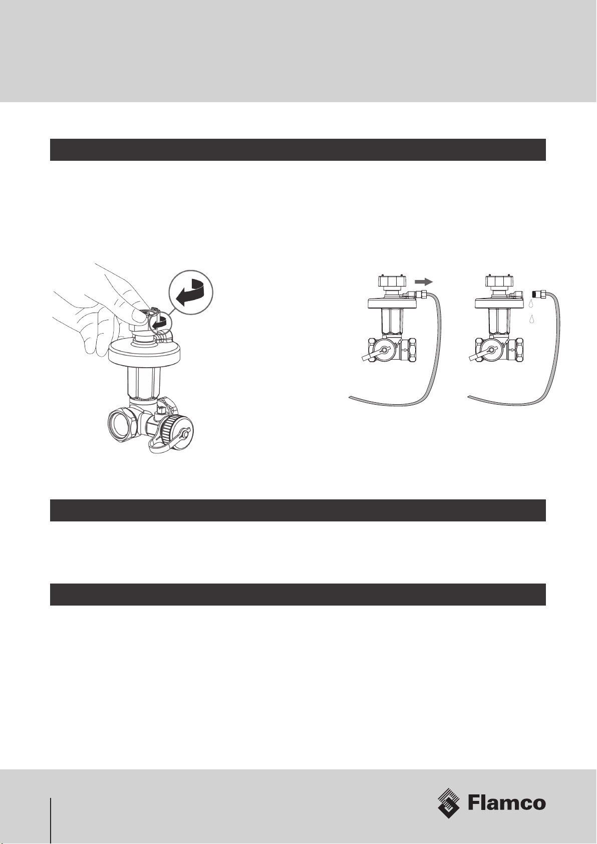
The capillary tube of the
DPCV needs to be flushed
to ensure that there are no
air pockets le in the tube.
Carefully loosen the tube on
the valve body and bleed the
air. Re-assemble the tube
aerwards. Also check that
the valve is fully opened.
4.1 Commissioning
Before starting commissioning, please ensure that all connections are correctly fitted and tightened. When checking
connections, use 2 wrenches in order to counteract any torsion force within the rest of the assembly. Some threaded
connections (not union connections) may have been assembled using a glue like thread sealant. Make sure that these
connections are never rotated! Check the expansion vessel pressure (should be operating pressure of the secondary
heating system) and adjust if necessary. Standard operating pressure is 1.5 bar. The expansion vessel is part of the pre-
plumbed cylinder package and is not supplied with the HIU.
4. Service

11
• Close all isolation ball valves.
• Ensure the electricity supply is switched o.
• Check visually for leaks (union connections, ball valve
connections)
• Check all pipework connected to the unit is clean and free from
debris, flux or limescale.
• Check the strainer (2) for debris and swarf. Take extra care
when removing the strainer cap (sensor cable), then check the
gauze. The gauze should be clean, clean the gauze if necessary.
Reassemble all strainers, replace any damaged 0-rings or fibre
seals.
• Check the setting of the return temperature limiter (9). Please
refer to Appendix A - Locking temperature setting of the
thermostatic head.
• Check all cables for damage and make sure that they
are tied together in a safe place (e.g. M-Bus cable o
hot pipes) without any tension.
• Open the isolation ball valves and ensure there are
no visible leaks.
• Switch on the electricity supply.
• Check the functionality of the system. Turn up the
room thermostat and push the override button on
the timer to get a call for heat. This will activate the
HIU delivering heat to the radiators and/or the DHW
circuit. Make sure that at least one TRV on a radiator
circuit is open. It will take some minutes to start
heating the apartment/ cylinder.
• Also check the max. primary flow rate using the heat
meter (pos. 3). Adjust the flow rate if necessary at
the zone valve (9) by removing the actuator head as
shown and turning the flow restrictor (A).
230 V ~, 50Hz
LN
Timer
Room
Thermostat
e.g. Standard Unit:
Adjusting the temperature of
the thermostatic valve.
Setting range: 20 ... 65ºC
(Factory locked to 40°C).
Strainer (2)
4.4 Service Check List
4. Service
A
1
3
4
5
6
3
7
7
2
9
AB CD
6 RAM40 1234 5678
Heat Meter
Quick Mode
Type775
0102
LCD Loop3: Installation
Class 2
E2 / M2
IP 54
Service activity needs to be logged in the service record of the unit including
date, servicing company and service engineer‘s name. Any faults recorded
need to be rectified immediately. Perform a functional test of the unit before
proceeding to the next step. Record the findings and rectify any problems
before proceeding.
3
T
M
∑
1
1
27
77
9
6
4
A
B
C
D
5
12
Error code Description
C -1 Basic parameter error in flash or RAM
E1 Temperature range exeeded [-19.9 °C ... 199.9 °C] e.g. sensor
cable short circuit
E 3 ** Flow and return sensors inverted/confused
E4 Hardware fault in ultrasonic unit, e.g. transducer or trigger
faulty or short circuit
E5 Reading interval too short. No communication possible.
E 6 ** Wrong flow direction (flow sensor)
E7 Undetermined flow sensor reading (air, debris)
E8 No (mains) power supply, running on the backup battery
E9 Battery discharged
E A* leakage, broken pipe
Eb * leakage, heat meter
EC * leakage, pulse input 1
Ed * leakage, pulse input 2
* optional, ** application dependet
The Table shows the list of error codes which might be
shown on the display. “E-7“ is the general error that is
shown when the HIU has not been filled (air in flow sensor).
For further information please refer to the leaflet of the heat meter (Installation Guide) supplied with the HIU or refer to the
comprehensive manual for the heat meter.
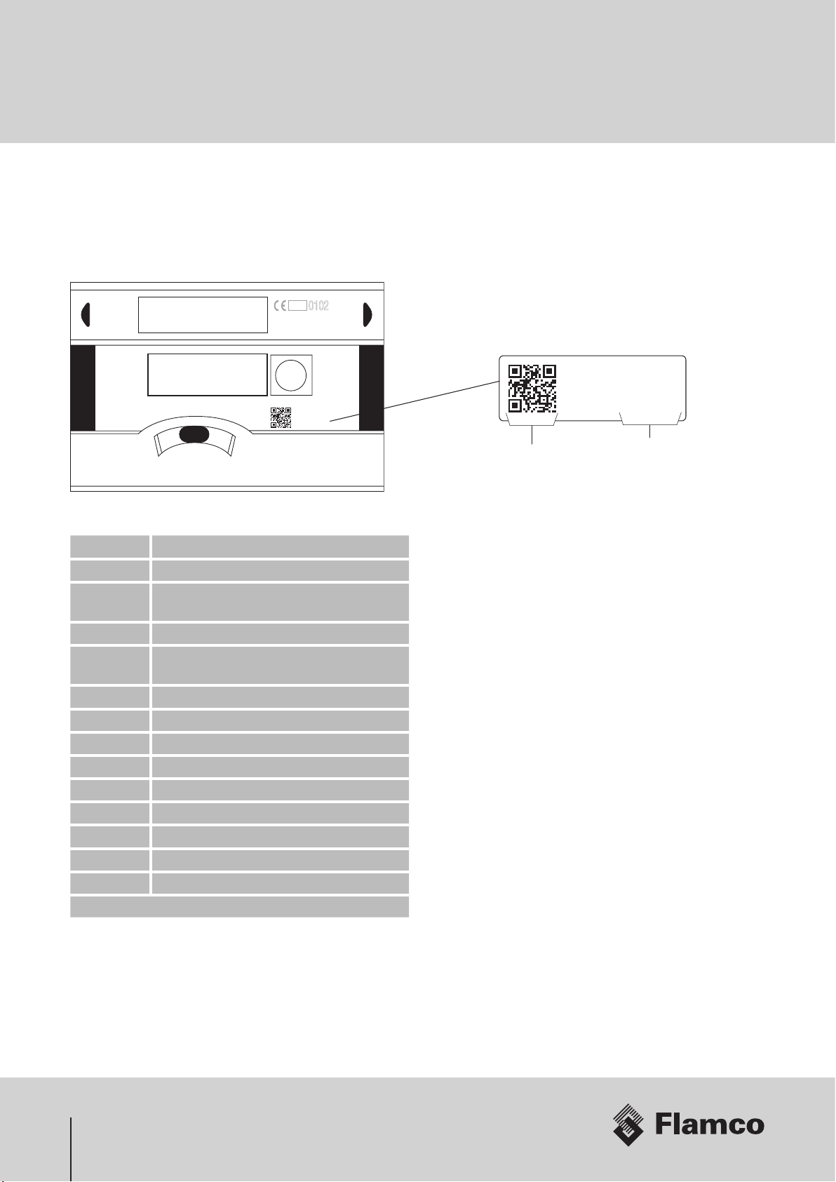
The HIU‘s factory fitted heat meter is an MID class 2 (RHI certified), battery or mains powered ultrasonic heat meter with
M-Bus functionality. You can scroll through the menu shortly pressing the black button next to the display. The serial
number (8 digit number) can be found as shown in the picture.
5. Heat Meter
6 RAM40 1234 5678
Heat Meter
Quick Mode
Type 775
0102
LCD Loop3: Installation
Class 2
E2 / M2
IP 54
6 RAM40 1234 5678
Heat meter
serial number
QR code
13
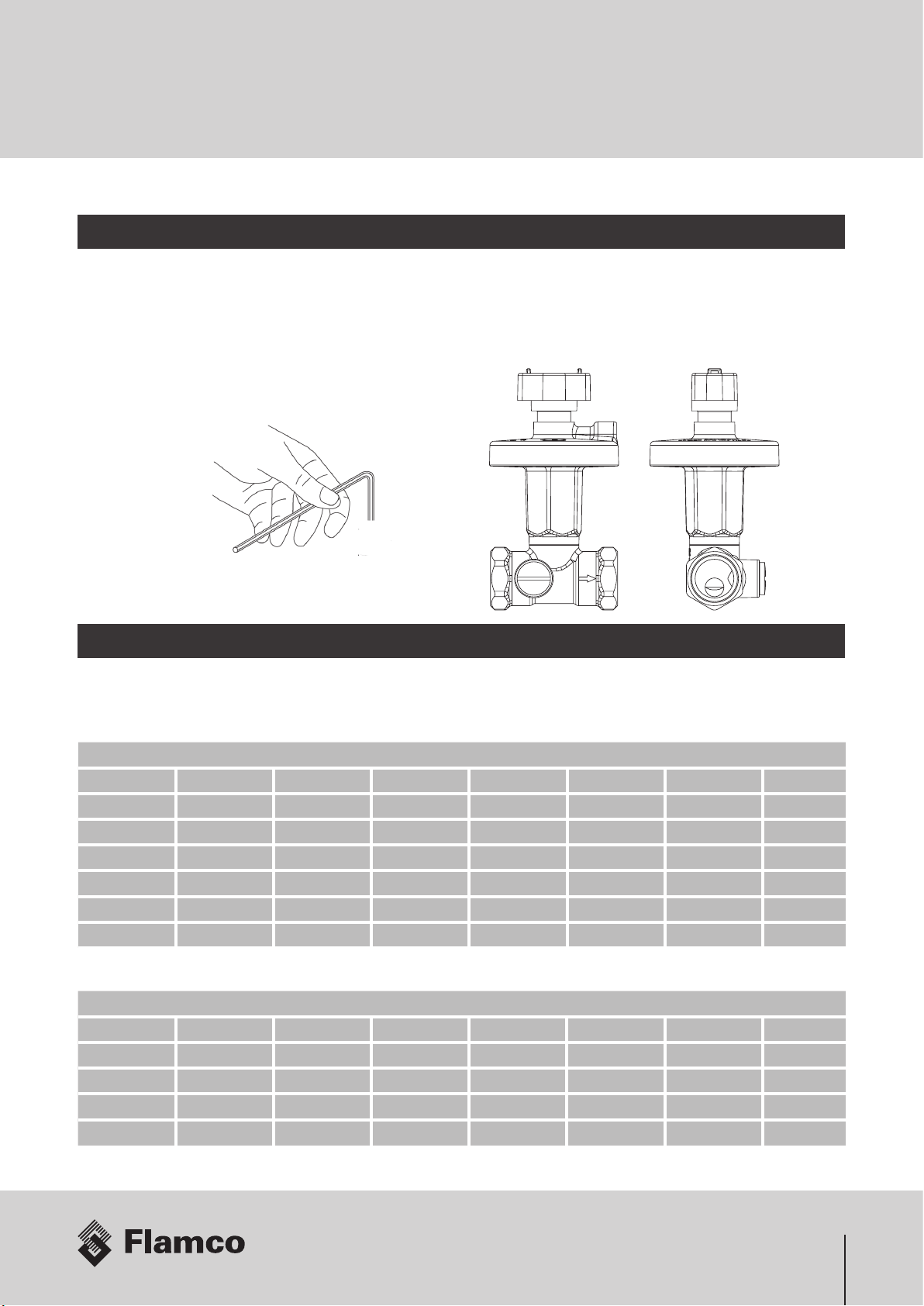
Adjusting the settings of the DPCV
Fitted into the HIU the DPCV has been set-up in the factory to 13,5 kPa (DN15) / 40 kPa (DN20). If this needs re-adjusting
do the following steps: Use the 3mm Allen key provided with the unit to turn the screw anti-clockwise until it is loosened.
According to the table below turn the key clockwise the number of rounds to the new required setting.
DN20 factory setting = 40 kPa (Standard Unit and 30 kW High Pressure Unit) 20 ... 40 kPa
Turns dp [kPa] Turns dp [kPa] Turns dp [kPa] Turns dp [kPa]
1 20.0 6 26.1 11 32.6 16 39.2
2 21.0 7 27.4 12 33.9 17 40.0
3 22.2 8 28.7 13 35.2
4 23.5 9 30.0 14 36.5
Dierential Pressure Control Valve (DPCV) - Ballorex® DN15, DN20
The DPCV fitted in the primary circuit of the HIU ensures that the pressure loss of the unit doesn‘t exceed DN15: 13,5 kPa,
DN 20: 40 kPa - factory setting. The valve itself is installed in the return. The pressure in the flow is received on top of the
membrane through the capillary tube. When the dierential pressure increases, the rising pressure on top of the internal
membrane forces the spring/spindle downwards closing the valve gradually, whereby constant pressure in the circuit is
obtained. The dierential pressure can be set between DN15: 5-25 kPa, DN 20: 20-40 kPa.
6. Appendix A
DN15 factory setting = 13,5 kPa (20 kW High Pressure Unit) 5... 25 kPa
Turns dp [kPa] Turns dp [kPa] Turns dp [kPa] Turns dp [kPa]
0 5.0 6 11.0 12 17.0 18 23.0
1 6.0 7 12.0 13 18.0 19 24.0
2 7.0 8 13.0 14 19.0 20 25.0
3 8.0 9 14.0 15 20.0
4 9.0 10 15.0 16 21.0
5 10.0 11 16.0 17 22.0
14
6. Appendix A
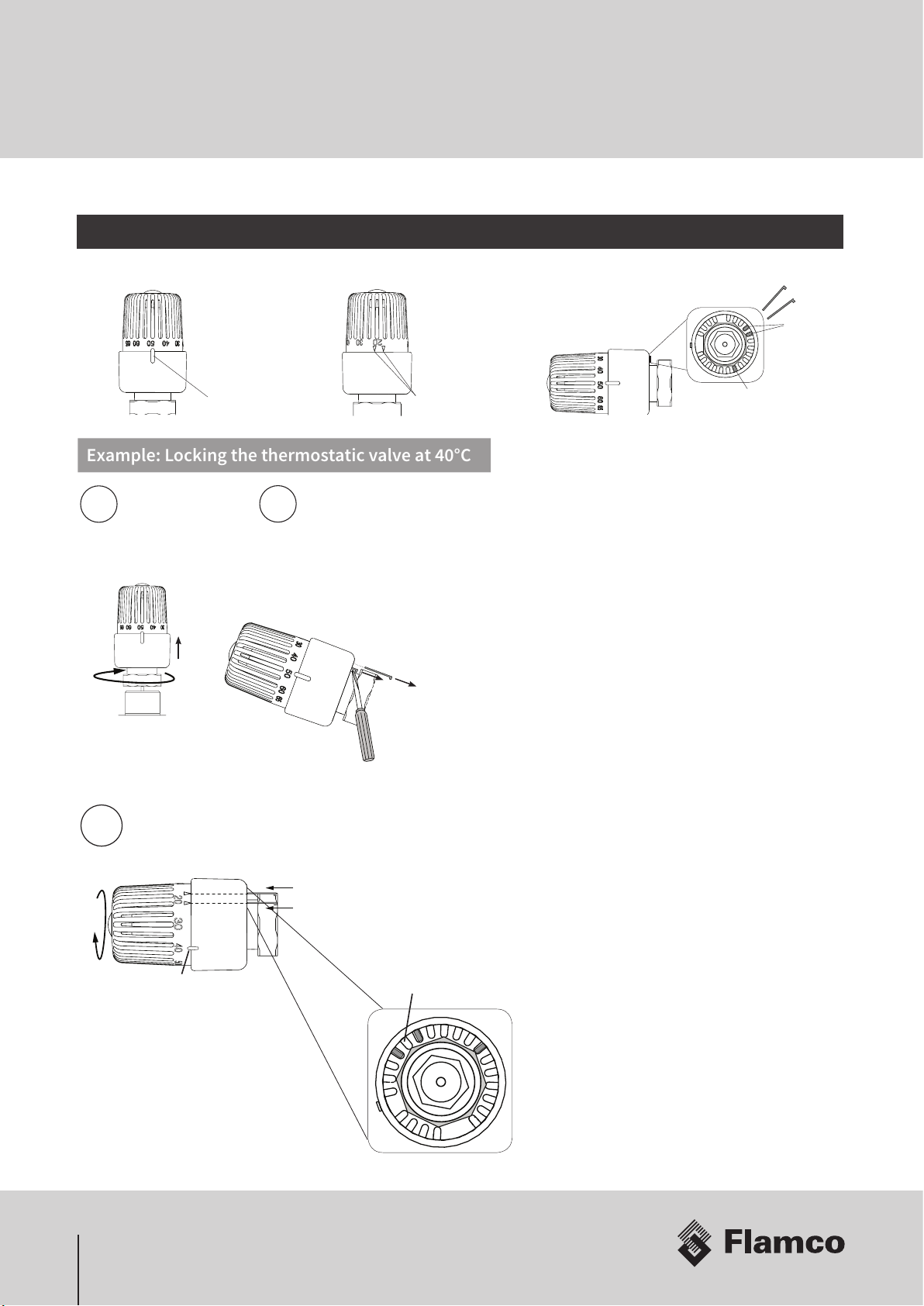
Locking the temperature setting
Set Temperature Index Alignment Marks
Metal Pins
Single Metal Pin
(not to be removed)
2x
Remove the two
metal pins using a
screw driver
12
Remove the thermostatic
head from the valve body
3
Select the temperature by
turning the head until the
index is pointing at 40ºC
To lock the head align the two
metal pins with the marks as
shown and push them back in
Make sure there is
a space between the two pins
Locking the Temperature Setting (Standard Unit)
Example: Locking the thermostatic valve at 40°C

15
Mains Supply
The mains supply needs to be protected by a 5A fuse and a double pole switch so that the unit can be safely disconnected
for servicing.
Fitting of the Heat Meter
The heat meter is optional and can be fitted by replacing the spool piece. Details will be found in the meter documentation.
System Testing
Finally test the system to ensure it is operating properly. This can only be done if the primary heat network is running
and the heating controls are wired in and switched on. Ensure that all isolation ball valves at the HIU are open as well as
one domestic hot tap. Hot water should be flowing from the tap in a very short time. To test the heating turn up the room
thermostat and push the override button on the timer get a call for heat. This will activate the HIU delivering heat to the
radiators or the underfloor heating circuit. Make sure that at least one TRV on a radiator or underfloor heating circuit is
open. It will take some minutes to start heating the apartment but the response of the unit can be checked immediately by
measuring the temperature of the primary and secondary flow pipes at the HIU.
Servicing
Service activity needs to be logged in the service record of the unit including date, servicing company and service
engineer‘s name. Any faults recorded need to be rectified immediately. Perfom a functional test of the unit before
proceeding to the next step. Record the findings and rectify any problems before proceeding.
Visual Check
Perform a visual check of the unit making sure all seals are water tight and there are no visible leaks. Any leaks need to be
fixed, union nuts tightened and seals replaced.
Cleaning the Strainers
Close all isolation ball valves and drain all circuits of the unit. Remove the strainer cap, then the strainer and clean the
strainer gauze. Reassemble all strainers, replacing any rubber or fibre seals. Then fill and bleed the entire unit ensuring
there are no leaks.
6. Appendix A
16
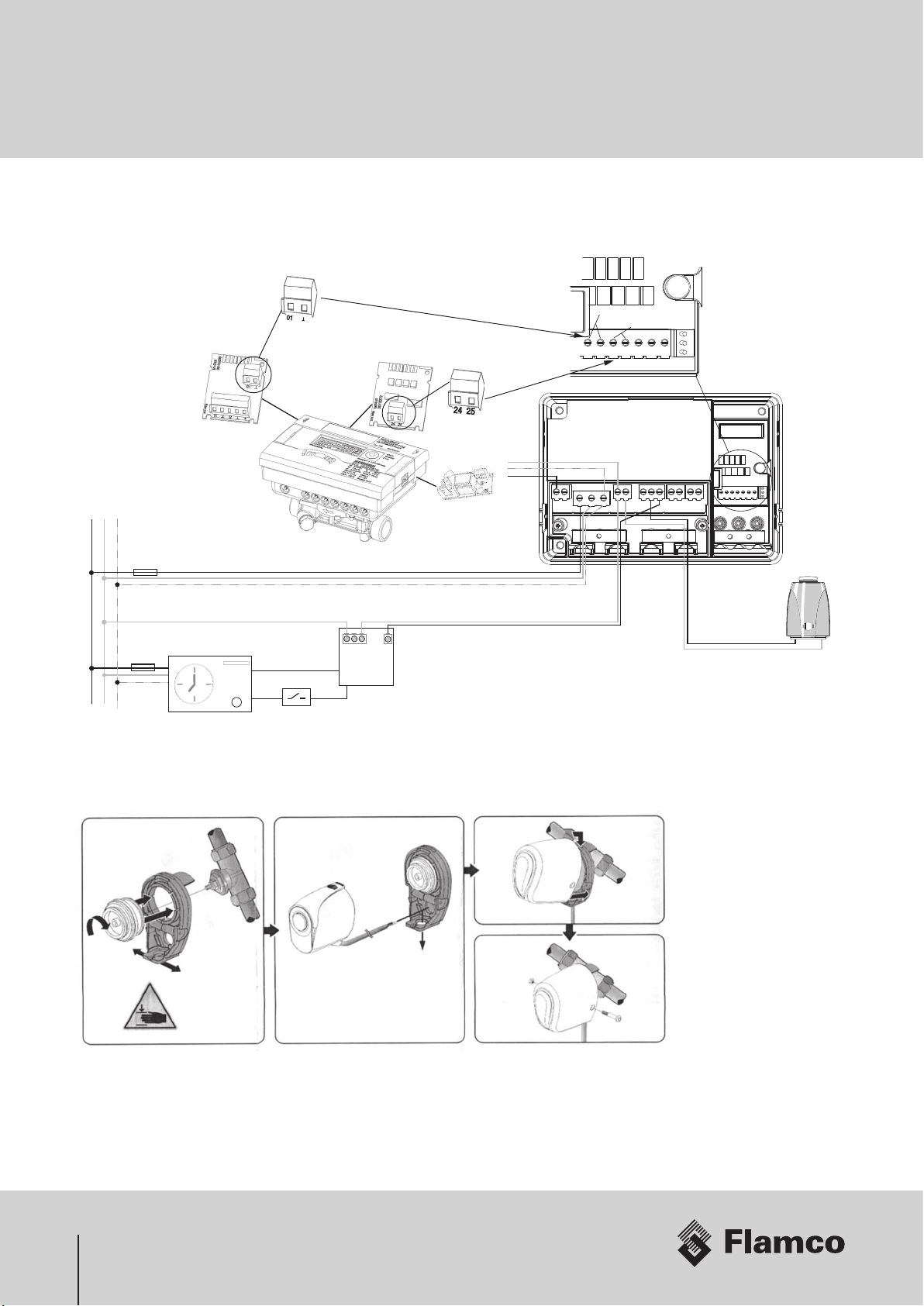
L2L1
N1 N2
R1 R2 R3
NO C NO C
NO NC C
N
N
L
PE
230V ~
Boiler Call
Fuse / Switch
Channel: Space Heating
Channel: Hot Water
brown blue
Room Thermostat
Wiring Centre of
Unvented Pre-plumbed Cylinder
Actuator Head
in HIU
Wiring Centre
Fuse
(non switched, 5A)
Heat Meter
M-Bus
Pulse
Pulse Inputs
Pulse Output
Pulse Module
M-Bus Module
24 25
01
24 25
2 core cable
2 core cable
L N PE
230V ~ Module
N
PE
L
Pre-Payment example (GURU System)
Securing Zone/Pre-Payment Actuator
7. Appendix B

17
The filter should be added to the requirements of the
“Operating and Maintenance” instructions handed over with
the system. If an advisory sticker is provided with the filter it
should be attached at a suitable location as to indicate the
presence within the system of the filter to ensure periodic
checking & servicing by any attending Service Engineer.
We would also recommend that these filters incorporate a
sight glass, particularly on the larger sizes to provide a visual
means of assessing corrosion without the need to disrupt
the operation of the system for checking.
Line Size Magnetic Field Strength
DN15 7500 gauss
DN20 9000 gauss
DN25 10500 gauss
DN35 21000 gauss
DN40 21000 gauss
DN50 52500 gauss
DN80 73500 gauss
DN100 73500 gauss
DN150 94500 gauss
Guidelines for System Conditioning of Heating Networks for Flamco Limited - Meibes Heat Interface Units (HIU)
Flamco Limited prides itself on bringing to the UK market a proven range of Heating Interface Units (HIU). To ensure that
our products deliver increased longevity and performance, these guidelines are specifically written to aid and ensure
both the primary and secondary side of the heat network are designed, installed and commissioned to realise the desired
heating comfort levels. These guidelines are not oered for use on potable, domestic, and water draw o side of
the system. Solely for the heating circuits ONLY. For further guidance on water treatment and water analysis
please refer to BSRIA BG29/2012, BG50/2013 and BS8552. Whilst not exhaustive, we oer these guidelines from
experience and a practical standpoint, in addition, as a check list to support design review. These guidelines are not
intended as mandatory or fixed in their approach; moreover they are intended as supporting documentation to highlight
good practise and methodology ensuring operation and maintenance activities are kept to a minimum post handover. We
are not specialists in the design, installation and or cleaning and subsequent treatment of water systems but, nevertheless,
contained in the sections below are importance aspects to consider.
1. System Design Considerations
• A review of the system should be undertaken post the design stage. The review should focus on the allocation,
location and capacity of strainers both fixed and temporary, air and gas removal devices, debris traps, isolation
valves to ensure that removal of debris from the system which was not removed in the commissioning activity is
managed and that sub sections can be economically isolated to permit maintenance.
• It should be considered at the design stage to include into the design a means ferrite removal. Poorly commissioned
and maintained systems exhibit corrosion. As the majority of systems contain products manufactured from iron, it is
the iron in the form of steel ferrite which creates the tell tale black sludge or blacked water which indicates corrosion
is taking place of components of the system. This corrosion if remaining unchecked, fouls water ways and controls,
erodes system components, reduces system performance and leads the production of hydrogen in the system
known as “Gassing”. This is also a tell tale sign of system corrosion.
• As over 90% of debris in systems is ferrous we recommend the installation of a rare earth, magnetic filter to both
remove the ferrite but act as a means of identifying corrosion is taking place and a prompt for remedial action.
• The removal device ideally, should have a first pass rate of 75% debris removal or greater, have incorporated into
it a static mixing function to open the system fluid to permit rapid removal of the debris, mounted in the common
return, main return pipe work. The filter shall be of adequate size and capacity to allow suicient flow rate and
debris capture for the system size (line size is recommended). Any such filter should have the following magnetic
field strength capacity as a minimum to ensure maximum ferrite removal.
8. Appendix C

18
2. Main Factors aecting corrosion and System performance
• “PH” or relative Acidity/ Alkalinity are of key importance in managing the production of system corrosion. It is
recommended that PH Level of the system water be between 7 and 8.5 (ideally 7.4/7.5). A Lower PH level than
recommended would be classed as acidic and corrode all metals. Alternatively, too high a PH level would be
alkaline and will corrode aluminium components within the wetted part of the system.
• When considering a chemical treatment product to add to the system, we recommend products which incorporate a
mix for buering, in order to control the PH level more eectively.
• Oxygen Ingress should be minimised by the use of closed systems and barrier pipe within the system design.
• Aggressive ions (such as flux residues) promote corrosion and, continue to do so unless neutralised or flushed out
completely. Wewould recommend a jointing approach that removes the need to use such compounds and adopt
the use of heat free systems.
• If traditional solder fittings are used then we would recommend the use of a recognised chemical treatment to flush
out and neutralise the system.
• The accumulation of sludge & debris can cause deposit corrosion which leads to pitting. We recommend the use
of a recognised chemical treatment to flush out and neutralise the system In addition, it is strongly advised to
contact the manufacturer of the chemical treatment to gain early involvement prior to treatment as to the correct
application and chemical to use.
3. Refurbishment and Improvement to existing systems
• It is vitally important that before commencing works on existing systems that a complete scan of the water quality
of the system be taken. If it is found that the system contains products of corrosion and/or PH levels in excess of
the required norms, it is recommended that the existing water is conditioned and treated to PRIOR to the work
commencing.
4. System commissioning (water quality) Water Treatment Chemicals
• We do not recommend the use of raw water for hydraulic testing due to the risk of corrosion of the water being le in
the system and potentially, the internals of the system being exposed to the air due to partial draining.
• Chemically dosed water should be in all filling in activities accordance with the chemical manufacturers’
recommendations and in accordance with BSRIA BG29 2012.
• Aer a suitable filling and flushing regime is used, relevant to the system material, all chemicals used to be suitable
for HIU must comply with EU norms DIN EN 12828 and current guidelines for heating systems. In addition, they
should also be non hazardous, non toxic and biodegradable.
• The use of correct cleaners and inhibitors is of primary, environmental concern. All chemicals used to treat the
system should not contain phosphates, sulphuric acid, nitrites. See BS7593:2006 Code of Practice for treatment of
water in domestic hot water central heating systems.
• Inhibitors should meet Buildcert as a minimum and preferably be recommended by the Energy Savings Trust (EST).
8. Appendix C

19
• Acid based cleaners are unsuitable for older systems as there is a risk of “pinholing” on radiators. They will also
require some form of neutralisation process before being discharged or require being tankered away for disposal.
5. Recommendations for system conditioning - (Basic process)
• The system must be flushed and inhibited in accordance with BS7593 and the Domestic Building Services
Compliance Guide.
• The chemicals used should contain the following aspects of their composition:
–Surfactants to reduce surface tension allowing chelating agents to attach to the residues.
–Chelating agents will then entrap the calcium carbonate within the solution.
–Dispersants are used to hold residues in suspension.
–The inhibitor then prevents corrosive attacks on metals during cleaning.
–PH Buers to maintain a neutral PH
–Chemicals shall be of a type suitable for disposal through a conventional sewer or foul drain (i.e. no requirement
for tankering or specialist disposal)
–Neutralisation
6. Site installation conditions – Installation of the system
It is recommended that:
–Water soluble flux should be used (no Chloride – COSSH).
–The area of installation should be free from gypsum dust, brick dust, screed or other possible contaminants.
7. Recommended aercare (HIU) Network Primary side
• Any relevant details of the installed units and system conditioning to be documented on the service record
• There should be clear notification of any chemical products added, dates etc placed on the HIU
• If there is a requirement for a partial drain down, the inhibitor should be topped up to the required level with full
details.
• We recommend that all servicing/inspection etc is fully adhered to.
• Any checklist sticker placed within the casing by the manufacturer must be completed. 8 Recommended aercare
(Network)
8. Appendix C

20
8. Recommended aercare (Network)
It is recommended that a regime of periodic inspection of the system be undertaken. The inspection shall take the form of:
Visual inspection
System visual inspection, exterior corrosion, water stains on the pipe work and equipment, suggesting a slow leak and
make up water entering the system thereby diluting the inhibitor concentrations.
Water Samples
Water samples shall be drawn from a suitable draw o point to ascertain the condition of the network, on the primary side
water.
The analysis of the water should include:
• Visual assessment – Note any discolouration away from clear as an indicator of possible corrosion
• Chemical assessment – PH value, hardness, precipitate composition and concentration of chemical treatment and type of
treatment contained within the water (A UKAS registered lab is recommended to be used in the system water analysis).
8. Appendix C
Table of contents


