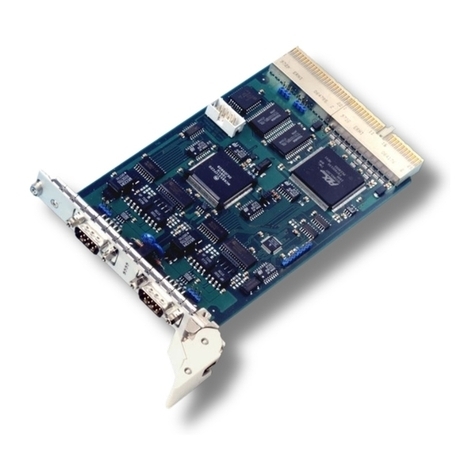
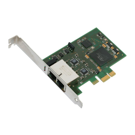
ESD CPCI-PN-DEV User manual

CPCI-PN-DEV
PROFINET® IO /CompactPCI® Interface
Manual
to Product I.2329.02
CPCI-PN-DEV Manual • Doc. No.: I.2329.21 / Rev. 1.3 Pa e 1 of 30
esd electronics gmbh
Vahrenwalder Str. 207 • 30165 Hannover • German
http://www.esd.eu
Phone: +49 (0) 511 3 72 98-0 • Fax: +49 (0) 511 3 72 98-68

N O T E
The information in this document has been carefully checked and is believed to be entirely reliable.
esd makes no warranty of any kind with re ard to the material in this document, and assumes no
responsibility for any errors that may appear in this document. In particular descriptions and
technical data specified in this document may not be constituted to be uaranteed product features
in any le al sense.
esd reserves the ri ht to make chan es without notice to this, or any of its products, to improve
reliability, performance or desi n.
All ri hts to this documentation are reserved by esd. Distribution to third parties, and reproduction
of this document in any form, whole or in part, are subject to esd's written approval.
© 2017 esd electronics mbh, Hannover
esd electronics mbh
Vahrenwalder Str. 207
30165 Hannover
Germany
Phone: +49-511-372 98-0
Fax: +49-511-372 98-68
E-Mail: [email protected]
Internet: www.esd.eu
This manual contains important information and instructions on safe and efficient
handlin of the CPCI-PN-DEV. Carefully read this manual before commencin any work
and follow the instructions.
The manual is a product component, please retain it for future use.
Trademark Notices
CANopen® and CiA® are re istered community trademarks of CAN in Automation e.V.
PROFINET® is a re istered trademark of PROFIBUS and PROFINET International (PI).
CompactPCI® and PICMG® are re istered trademarks of the PCI Industrial Computers Manufacturers Group.
QNX® is a re istered trademark of QNX Software Systems Limited, and is re istered trademark and/or used in certain
jurisdictions.
All other trademarks, product names, company names or company lo os used in this manual are reserved by their
respective owners.
Pa e 2 of 30 Manual • Doc. No.: I.2329.21 / Rev. 1.3 CPCI-PN-DEV

Document file I:\Texte\Doku\MANUALS\CPCI\CPCI-PN-DEV\En lisch\CPCI-PN-DEV_Manual_en_13.odt
Date of print 2017-07-28
Document type
number DOC0800
Hardware version 1.0
Document History
The chan es in the document listed below affect chan es in the hardware as well as chan es in
the description of the facts, only.
Revision Chapter Changes versus previous version Date
1.0 - First En lish manual 2014-02-11
1.1
- Note about data safety added to Safety Instructions
2014-09-23
4.2 Description of LED Indication for LED L and B revised
9. New Chapter “PROFINET IO Certificate”
10. Chapter “Order Information” moved
1.2
- Safety information revised
2015-011-05
3. Chapter revised
7.4 New chapter: “Usin the CPCI-PN-DEV with the TIA Portal V13SP1”
9. Order Information of Linux driver inserted
1.3 8. New PROFINET IO Certificate inserted 2017-07-28
Technical details are subject to chan e without further notice.
CPCI-PN-DEV Manual • Doc. No.: I.2329.21 / Rev. 1.3 Pa e 3 of 30

Safety Instructions
● When workin with the CPCI-PN-DEV follow the instructions below and read the manual carefully to protect yourself
from injury and the CPCI-PN-DEV from dama e.
● The device is a built-in component. It is essential to ensure that the device is mounted in a way that cannot lead to
endan erin or injury of persons or dama e to objects.
● The device has to be securely installed in the control cabinet before commissionin .
● Protect the CPCI-PN-DEV from dust, moisture and steam.
● Protect the CPCI-PN-DEV from shocks and vibrations.
● The CPCI-PN-DEV may become warm durin normal use. Always allow adequate ventilation around the CPCI-PN-
DEV and use care when handlin .
● Do not operate the CPCI-PN-DEV adjacent to heat sources and do not expose it to unnecessary thermal radiation.
Ensure an ambient temperature as specified in the technical data.
● Do not use dama ed or defective cables to connect the CPCI-PN-DEV.
● In case of dama es to the device, which mi ht affect safety, appropriate and immediate measures must be taken, that
exclude an endan erment of persons and domestic animals and property.
● Current circuits which are connected to the device have to be sufficiently protected a ainst hazardous volta e (SELV
accordin to EN 60950-1).
● The CPCI-PN-DEV may only be driven by power supply current circuits, that are contact protected.
A power supply, that provides a safety extra-low volta e (SELV or PELV) accordin to EN 60950-1, complies with this
conditions.
DANGER
Hazardous Voltage - Risk of electric shock due to unintentional contact with uninsulated live parts with hi h
volta es inside of the system into which the CPCI-PN-DEV is to be inte rated. Disconnect all hazardous
volta es (mains volta e) before you install the CPCI-PN-DEV into the system.
NOTICE
Electrostatic discharges may cause damage to electronic components.
To avoid this, please perform the steps described on pa e 8 before you touch the CPCI-PN-DEV, in order
to dischar e the static electricity from your body.
Qualified Personal
This documentation is directed exclusively towards personal qualified in control and automation en ineerin .
The installation and commissionin of the product may only be carried out by qualified personal, which is authorized to
put devices, systems and electric circuits into operation accordin to the applicable national standards of safety
en ineerin .
Conformity
The CPCI-PN-DEV is an industrial product and meets the demands of the EU re ulations and EMC standards printed in
the conformity declaration at the end of this manual.
Warning In a residential, commercial or li ht industrial environment the CPCI-PN-DEV may cause radio interferences
in which case the user may be required to take adequate measures.
Data Safety
This device is equipped with an Ethernet or other interface which is suitable to establish a connection to data networks.
Dependin on the software used on the device, these interfaces may allow attackers to compromise normal function, et
ille al access or cause dama e.
esd does not take responsibility for any dama e caused by the device if operated at any networks. It is the responsibility
of the device's user to take care that necessary safety precautions for the device's network interface are in place.
Intended Use
The intended use of the CPCI-PN-DEV is the operation as PROFINET® IO interface in a CompactPCI® system.
The uarantee iven by esd does not cover dama es which result from improper use, usa e not in accordance with
re ulations or disre ard of safety instructions and warnin s.
● The CPCI-PN-DEV is intended for installation in a CompactPCI-system only.
● The operation of the CPCI-PN-DEV in hazardous areas, or areas exposed to potentially explosive materials is not
permitted.
● The operation of the CPCI-PN-DEV for medical purposes is prohibited.
Service Note
The CPCI-PN-DEV does not contain any parts that require maintenance by the user. The CPCI-PN-DEV does not
require any manual confi uration of the hardware.
Disposal
Devices which have become defective in the lon run have to be disposed in an appropriate way or have to be returned
to the manufacturer for proper disposal. Please, make a contribution to environmental protection.
Pa e 4 of 30 Manual • Doc. No.: I.2329.21 / Rev. 1.3 CPCI-PN-DEV
Table of contents
Safety Instructions...........................................................................................................................4
1. Overview...................................................................................................................................... 6
2. PCB View with Connectors...........................................................................................................7
3. Hardware Installation ...................................................................................................................8
4. LEDs............................................................................................................................................ 9
4.1 Position of the LEDS.............................................................................................................. 9
4.2 LED Indication.......................................................................................................................9
5. Technical Data...........................................................................................................................11
5.1 General Technical Data.......................................................................................................11
5.2 CPU and Memory................................................................................................................11
5.3 CompactPCI Bus................................................................................................................. 12
5.4 PROFINET IO...................................................................................................................... 12
6. Connector Assi nments.............................................................................................................13
6.1 PROFINET IO...................................................................................................................... 13
7. Software..................................................................................................................................... 14
7.1 Firmware.............................................................................................................................. 14
7.2 Host-Operatin System and Drivers.....................................................................................15
7.2.1 PNCTL_START...........................................................................................................15
7.2.2 PNCTL_SEND.............................................................................................................16
7.2.3 PNCTL_TAKE.............................................................................................................16
7.3 Library and Application Software ........................................................................................17
7.4 Usin the CPCI-PN-DEV with the TIA Portal V13SP1..........................................................19
7.4.1 Quick Start.................................................................................................................. 19
7.4.2 Installation of the GSDML File.....................................................................................20
7.4.3 Insert CPCI-PN-DEV Hardware and Network Confi uration........................................22
7.4.4 Customize the automatically enerated Name............................................................23
7.4.5 Insert I/O Words for Exchan e of Information..............................................................25
7.4.6 Compile Hardware Confi uration.................................................................................25
7.4.7 Go online..................................................................................................................... 26
8. Declaration of Conformity...........................................................................................................28
9. PROFINET IO Certificate...........................................................................................................29
10. Order Information..................................................................................................................... 30
CPCI-PN-DEV Manual • Doc. No.: I.2329.21 / Rev. 1.3 Pa e 5 of 30

Overview
1. Overview
Figure 1 Block circuit dia ram
The CPCI-PN-DEV can link any PROFINET IO® controller to a CompactPCI® system and operates
as a PROFINET IO device with a maximum of 1440 bytes input data and 1440 bytes output data
on the PROFINET IO bus.
Four PROFINET IO interfaces, accessible via the front panel, ive an excellent base for
PROFINET IO applications.
The module inte rates a CompactPCI-based application into the PROFINET IO network, e. . a
SIMATIC-S7.
The CPCI-PN-DEV is a CompactPCI board in 3U format. The 100 BASE-TX PROFINET IO
interface is compatible to IEEE802.3 and runs with 100 Mbit/s. The PROFINET IO interface is
electrically isolated.
The module can be confi ured via PROFINET IO confi uration tool, e. . the PLC SIMATIC
Mana er. No additional confi uration tools are required!
Software support is available for QNX®.
Drivers for other operatin systems are available on request.
Pa e 6 of 30 Manual • Doc. No.: I.2329.21 / Rev. 1.3 CPCI-PN-DEV
PHY
PHY
PHY
PHY
ERTEC400
ERTEC400
16 kB
EEPROM
16 kB
EEPROM
32 MB
SDRAM
32 MB
SDRAM
PORT 1
RJ45
100BASE-TX
PORT 2
RJ45
100BASE-TX
PROFINET IO
PORT 3
RJ45
100BASE-TX
PORT 4
RJ45
100BASE-TX
CompactPCI
Connector
IRQ

Hardware Installation
3. Hardware Installation
Read the safety instructions at the beginning of this document carefully, before
you start with the hardware installation!
DANGER
Hazardous Voltage - Risk of electric shock due to unintentional contact with
uninsulated live parts with hi h volta es inside of the system into which the CPCI-PN-
DEV is to be inte rated. Disconnect all hazardous volta es (mains volta e) before you
install the CPCI-PN-DEV into the system.
NOTICE
Electrostatic dischar es may cause dama e to electronic components. To avoid this,
please perform the followin steps before you touch the CPCI-PN-DEV, in order to
dischar e the static electricity from your body:
Switch off the power of your computer, but leave it connected to the mains until
you have dischar ed yourself (if applicable).
Please touch the metal case of the computer now to dischar e yourself.
Furthermore, you should prevent your clothes from touchin the computer,
because your clothes mi ht be electrostatically char ed as well.
Procedure
1. Switch off your computer and all connected peripheral devices (monitor, printer, etc.).
2. Dischar e your body as described above.
3. Disconnect the computer from the mains.
If the computer does not have a flexible mains cable, but is directly connected to mains,
disconnect the power supply via the safety fuse and make sure that the fuse cannot switch
on a ain unintentionally (i.e. with caution label).
DANGER
Hazardous Volta e - Risk of electric shock due to unintentional contact with
uninsulated live parts with hi h volta es inside of the system into which the CPCI-
PN-DEV is to be inte rated. Disconnect all hazardous volta es (mains volta e)
before you install the CPCI-PN-DEV into the system. Ensure the absence of
volta e before startin any electrical work
4. Open the case.
5. Insert the CPCI-PN-DEV board into the selected CompactPCI slot. Carefully push the board
until it snaps into place.
6. Fix the CPCI-PN-DEV with the screws in the front panel.
7. Connect the PROFINET IO interfaces (Port1-4) via the connectors in the front panel of the
CPCI-PN-DEV.
8. Close the computer case a ain.
9. Connect the computer to mains a ain (mains connector or safety fuse).
10. Switch on the computer and the peripheral devices.
Pa e 8 of 30 Manual • Doc. No.: I.2329.21 / Rev. 1.3 CPCI-PN-DEV
LEDs
4. LEDs
4.1 Position of the LEDS
Figure 3 Connectors and LEDs
4.2 LED Indication
LED Colour Name Description
LED name
in schematic
dia ram
Freen Force PROFINET IO-Force, blinkin on request of the master LED530A
Lreen Link PROFINET IO-Link, data exchan e with PLC active LED530B
Breen Boot Application on CPCI-PN-DEV started LED530C
Preen Power Control by Power supervisor circuit, CPU started LED530D
Table 1 Description of LEDs
CPCI-PN-DEV Manual • Doc. No.: I.2329.21 / Rev. 1.3 Pa e 9 of 30

LEDs
PROFINET-IO-RJ-45-Socket-LEDs of PORT1 to PORT4
LED Colour Indication Description
Link reen off no PROFINET IO or Ethernet connection
on PROFINET IO or Ethernet connection exists.
Activity yellow off no PROFINET IO connection
flickerin PROFINET IO connection active
Table 2 Indication of the RJ-45-LEDs
Pa e 10 of 30 Manual • Doc. No.: I.2329.21 / Rev. 1.3 CPCI-PN-DEV
Technical Data
5. Technical Data
5.1 General Technical Data
Power supply
volta e
via CompactPCI bus:
nominal volta e: 3.3 V
current consumption typical at 3.3V: 400 mA
Connectors
PROFINET IO Port 1 - Port 2 8-pin dual port RJ45 (X620A/B)
- PROFINET IO Port 1, Port 2
PROFINET IO Port 3 - Port 4 8-pin dual port RJ45 (X820A/B)
- PROFINET IO Port 3, Port 4
Only for test- and pro rammin purposes:
X300
X540
7-pin Samtec RSM-107-02-L-S - JTAG interface
4-pin Samtec RSM-104-02-L-S - Debu console, TTL level
Temperature
ran e 0...50 °C ambient temperature
Humidity max. 90%, non-condensin
Dimensions Board: 100 mm x 160mm
Front panel: 3U x 4HP
Wei ht 170
Table 3 General data of the module
5.2 CPU and Memory
CPU Siemens ERTEC400, 150MHz
SDRAM 64 MByte SDRAM, 50MHz
EEPROM 16kByte SPI
Table 4 CPU and Memory
CPCI-PN-DEV Manual • Doc. No.: I.2329.21 / Rev. 1.3 Pa e 11 of 30

Technical Data
5.3 CompactPCI Bus
Host bus PCI-Bus accordin to PCI Local Bus Specification 2.2
PCI-data/address bus 32 Bit, 33/66 MHz
Board dimension accordin to CompactPCI-Specification PICMG® 2.0 R 2.1
Connector
Connector codin Universal-Board, not keyed
(3.3 V or 5 V si nallin volta e)
Table 5 Data of the CompactPCI bus
5.4 PROFINET IO
Number of
interfaces 4
Standard IEEE 802.3, 10BASE-T, 100BASE-TX
Bit rate 10/100 Mbit/s
Controller Inte rated in CPU
PHY Micrel KSZ8721BL
Connection Twisted Pair (compatible to IEEE 802.3), 100BASE-TX
Electrical isolation Via transformer
Connector 2x dual port RJ-45-sockets with inte rated LEDs in the front panel
Table 6 Data of the PROFINET IO interface
Pa e 12 of 30 Manual • Doc. No.: I.2329.21 / Rev. 1.3 CPCI-PN-DEV
Connector Assignments
6. Connector Assignments
6.1 PROFINET IO
Device connector RJ45 socket, 8-pin, assi ned accordin to IEEE 802.3-2008, Table 25-3
„UTP MDI contact assi nment“
Pin Position
Pin Assignment
Pin Signal Meaning
1 MDI0+ (TxD+) Transmit Data +
2 MDI0- (TxD-) Transmit Data -
3 MDI1+ (RxD+) Receive Data +
4 - -
5 - -
6 MDI1- (RxD-) Receive Data -
7--
8 - -
S Shield
The pins 1, 2, 3 and 6 are terminated.
Signal Description
MDI0+/-, MDI1+/- ... Data lines
- ... reserved for Gi abit applications
Shield... case shield, connected with the front panel of the CPCI-PN-DEV.
IMPORTANT
Cables of cate ory CAT5 or hi her have to be used to rant the function in networks
with 100 Mbit/s.
esd rants the EC conformity of the product, if the wirin is carried out with shielded
twisted pair cables.
CPCI-PN-DEV Manual • Doc. No.: I.2329.21 / Rev. 1.3 Pa e 13 of 30
12345678
S

Software
7. Software
7.1 Firmware
The input process ima e is stored in the host memory via bus masterin , the host-CPU
communicates the associated address via the confi uration field.
The output process ima e is provided by the ERTEC400 directly via CompactPCI.
The process ima e size is 1440 byte per direction, minus 1 byte per module and data direction
(IOPS and IOCS). For universal usa e input and output modules with the followin sizes are
provided: 1, 2, 4, 8, 16, 32, 64, 120 words with 16 bit.
Lar er modules do not make sense, because the ERTEC400 allows only consistency of up to
240 bytes per module.
Example: 5 input modules à 128 byte and 2 output modules à 8 byte result in
–5*128 + (5+2)*1 = 647 byte input
–2*8 + (2+5)*1 = 23 byte output
The process ima es are exchan ed with the driver without information about the validity (IOPS and
IOCS).
Operatin system eCOS
Driver Operatin system-specific
Licences Royalty-free
Update mechanism Not necessary, because the driver loads the firmware via CompactPCI
Pa e 14 of 30 Manual • Doc. No.: I.2329.21 / Rev. 1.3 CPCI-PN-DEV
Software
7.2 Host-Operating System and Drivers
Operatin system QNX 6.x
Drivers esd Resource-Mana er
Licenses esd
The resource-mana er provides the functionalities per devctl() with the followin commands
–PNCTL_START: Start the ateway application
–PNCTL_SEND: Transmit the input process data to PROFINET IO
–PNCTL_TAKE: Receive the output process data from PROFINET IO
7.2.1 PNCTL_START
PNCTL_START Start PN Slave
Input: PNSTART.node not used, only for compatibility reason
Output: PNSTART.baud not used, only for compatibility reason
PNSTART.buf_out_len Len of output buffer = PN Master Input Len
PNSTART.buf_in_len Len of input buffer = PN Master Output Len
devctl result: EOK => Firmware started. Look at pnStatus
EAGAIN => Firmware not started yet, try a ain
pnStatus: >=0 => Firmware runnin error-free
<0 => Firmware runnin with error code
Description: Start the ateway application
CPCI-PN-DEV Manual • Doc. No.: I.2329.21 / Rev. 1.3 Pa e 15 of 30

Software
7.2.2 PNCTL_SEND
PNCTL_SEND Chan e output data (= PN Master Inputs)
Input: PNDATA.offset Byte offset in output buffer
PNDATA.len Byte len to chan e
PNDATA.byte[] Output bytes
Output: -
devctl result: EOK => Look at pnStatus
EIO => Firmware not started!
EINVAL => Offset and/or len do not match the PN input buffer
pnStatus: >=0 => Data written
<0 => Firmware runnin with error code.
No data transferred.
Description: Transmit the input process data to PROFINET IO
7.2.3 PNCTL_TAKE
PNCTL_TAKE Read input data (= PN Master Outputs)
Input: PNDATA.offset Byte offset in input buffer
PNDATA.len Byte len to read
Output: PNDATA.byte[] Input bytes
devctl result: EOK => Look at pnStatus
EIO => Firmware not started!
EINVAL => Offset and/or len do not match the PN input buffer
pnStatus: >=0 => Data read
<0 => Firmware runnin with error code.
No data transferred.
Description: Receive the output process data from PROFINET IO
Pa e 16 of 30 Manual • Doc. No.: I.2329.21 / Rev. 1.3 CPCI-PN-DEV

Software
7.3 Library and Application Software
Application example PNTEST to explain the software interface.
#include <stdlib.h>
#include <stdio.h>
#include <string.h>
#include <errno.h>
#include <fcntl.h>
#include <time.h>
#include <sys/netmgr.h>
#include <sys/neutrino.h>
#include <esdpn.h>
PNSTART pnStart
PNDATA pnData
static void dumpBuffer(unsigned char *buffer, int len, int offset)
static void help(void)
static void help()
{
printf("pntest -t test -n node [-d device] [-r repeat delay] offs len [byte0 byte1...]\n")
}
int main(int argc, char **argv )
{
int option
int device = 0
int node = -1
int test = -1
int timeDelay =0
char devname[16]
int pnFd
int result
int32_t pnStatus
int i
int count=0
while( ( option = getopt(argc, argv, "t:n:d:r:h" ) ) != EOF ) {
switch(option) {
case 't':
test = strtoul(optarg, NULL, 0)
break
case 'd':
device = strtoul(optarg, NULL, 0)
break
case 'n':
node = strtoul(optarg, NULL, 0)
break
case 'r':
timeDelay = strtoul(optarg, NULL, 0)
break
case 'h':
help()
return -1
}
}
argc -= optind
argv += optind
if(argc >0) {
pnData.offset = strtoul(argv[0], NULL, 0)
}
if(argc >1) {
pnData.len = strtoul(argv[1], NULL, 0)
}
for( i = 2 i < argc i ++) {
pnData.byte[i-2] = (uint8_t)strtoul( argv[i], NULL, 0 )
}
if( -1 == test || -1 == node || argc < 2) {
help()
return -1
}
if( argc == 2) {
count =1
}
sprintf(devname,"/dev/pn%d", device)
pnFd = open(devname, O_RDWR )
if(pnFd == -1) {
perror("open failed")
return -1
}
pnStart.node = node
result = devctl( pnFd, PNCTL_START, &pnStart, sizeof(pnStart), &pnStatus )
if( 0 != result ) {
printf("DIOCTL_START:%s PN Status:0x%08x\n", strerror(result), pnStatus)
return -1
}
printf("PN-Node=%d Baudrate=%d, OutBufferLen=%d, InBufferLen=%d\n",
pnStart.node, pnStart.baud, pnStart.buf_out_len, pnStart.buf_in_len )
switch( test ) {
case 1:
{
do {
CPCI-PN-DEV Manual • Doc. No.: I.2329.21 / Rev. 1.3 Pa e 17 of 30

Software
result = devctl(pnFd, PNCTL_TAKE, &pnData, sizeof(pnData), &pnStatus)
if( 0 != result ) {
printf("DIOCTL_TAKE:%s\n", strerror(result) )
return -1
}
if( pnStatus < 0) {
printf("DIOCTL_TAKE: PN Status: 0x%08x\n", pnStatus )
} else {
dumpBuffer( pnData.byte, pnData.len, pnData.offset )
}
if( timeDelay ) {
delay(timeDelay)
}
} while( timeDelay )
break
}
case 2:
{
do {
result = devctl(pnFd, PNCTL_SEND, &pnData, sizeof(pnData), &pnStatus)
if( 0 != result ) {
printf("DIOCTL_SEND:%s\n", strerror(result))
return -1
}
if( pnStatus != 0) {
printf("DIOCTL_SEND: PN Status: 0x%08x\n", pnStatus )
}
if( timeDelay ) {
delay(timeDelay)
}
if( count) {
for(i=0 i < pnData.len i ++) {
pnData.byte[i] ++
}
}
} while( timeDelay )
break
}
default:
{
printf("Unknown test.\n")
}
}
return 0
}
static void dumpBuffer(unsigned char *buffer, int len, int offset)
{
int i, j
unsigned char lastBuf[16]
int line =0
int repeat =0
if( len >= 16 ) {
for( i = 0 i < len i +=16) {
if(line >0) {
if(0 == memcmp( &buffer[i], &lastBuf[0], 16) ) {
repeat ++
} else {
repeat =0
}
}
switch(repeat) {
case 0:
printf("\n%08x:", i+offset)
for( j = 0 j < 16 j ++){
printf(" %02x", buffer[i+j])
}
break
case 1:
printf("\n*")
break
}
memcpy( lastBuf, &buffer[i], 16)
line ++
}
} else {
i = 16
}
if( i > len ) {
i -=16
printf("\n%08x:", i+offset)
for( i < len i ++){
printf(" %02x", buffer[i])
}
}
printf("\n%08x\n", i+offset)
}
Pa e 18 of 30 Manual • Doc. No.: I.2329.21 / Rev. 1.3 CPCI-PN-DEV
Software
7.4 Using the CPCI-PN-DEV with the TIA Portal V13SP1
NOTICE
This chapter does only describe the steps which are relevant for the usa e of the esd
GSDML file and the CPCI-PN-DEV with the TIA Portal.
Please read the documentation of your TIA Portal for a detailed description.
7.4.1 Quick Start
Step Action see
page
1. Disconnect the online connection in your TIA Portal, because the
hardware and software have to be complied in offline mode! -
2. Chan e into the project view of your TIA Portal. -
3. Install the GSDML file as described in chapter „Installation of the
GSDML File“. 20
4. Insert the CPCI-PN-DEV in your project, see chapter „Insert CPCI-PN-
DEV Hardware and Network Confi uration“. 22
5. Customize the automatically enerated Name 23
6. Insert I/O Words for Exchan e of Information 25
7. Compile and load the hardware and software as described in chapter
„Compile Hardware Confi uration“. 25
8. Go online a ain. See Fi . 21. 27
9. Transmit and Receive process ima e
CPCI-PN-DEV Manual • Doc. No.: I.2329.21 / Rev. 1.3 Pa e 19 of 30

Software
7.4.2 Installation of the GSDML File
IMPORTANT
Before you start with the installation of the GSDML file for the CPCI-PN-DEV make sure
that your TIA Portal is offline.
In the pro ram window of your TIA Portal chan e into project view to import the device description
file. Click onto menu item Options in the main menu.
Figure 4 Options/Manage GSD
Choose Manage general station description files
(GSD) in the pull-down menu, see Fi ure 4.
Now the window Manage general station description
files opens.
Figure 5 Window Manage general station description files
If the path to the folder is not
already entered in the input field
Source path correctly, click onto
the Browse button [...] in the upper
ri ht part of the window Manage
general station description files to
choose it.
Figure 6 Select the path to the folder
In the window Ordner suchen (Search Folder)
you can now select the path to the GSDML
folder.
Click on the folder which contains the GSDML
file for the CPCI-PN-DEV, which you received
from esd.
Click the button OK to confirm the path.
Pa e 20 of 30 Manual • Doc. No.: I.2329.21 / Rev. 1.3 CPCI-PN-DEV
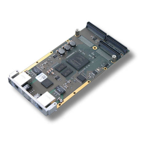
Table of contents
Other ESD Recording Equipment manuals

ESD
ESD C.2076.63 User manual

ESD
ESD VME - ASIO16 User manual

ESD
ESD CAN-ISA/331 User manual

ESD
ESD DN-PC104/331 Instruction manual

ESD
ESD CAN-CBX-THERMO User manual

ESD
ESD CPCI-CAN/400-4 User manual

ESD
ESD ECS-PMC/FPGA User manual

ESD
ESD CAN-PCI/402 User manual

ESD
ESD CPCI-ETH2 User manual

ESD
ESD CAN-CBM-CLOCK User manual

ESD
ESD CAN - PCC User manual

ESD
ESD CAN-PCI/405-B4 User manual

ESD
ESD CAN-USB/Micro User manual

ESD
ESD DTS2 User manual

ESD
ESD CAN-PCI/405 User manual

ESD
ESD CPCI-CAN/400-2 User manual

ESD
ESD ECS-PCIe/1100 User manual

ESD
ESD CAN-PCI104/200 User manual

ESD
ESD ECS-XMC User manual

ESD
ESD CAN-PC104/200 Instruction manual