flamco GPAIII Series User guide

ENG Installation and operating instruction
www.flamcogroup.com
Energy-saving Pipeline Canned Motor Pump
GPAIII series

2We reserve the right to change designs and technical specifications of our products.GPA III manual - 20211008
Table of Content
Notes ������������������������������������������������������������������������������������������������������������������������3
1� Symbol description �������������������������������������������������������������������������������������������������4
2.1. GPA III series circulating pump for water circulation... .............................................................. 4
2.2. Advantages of installation of the pump....................................................................................... 4
3� Service conditions���������������������������������������������������������������������������������������������������5
3.1. Ambient Temperature ................................................................................................................. 5
3.2. Relative humidity (RH) ................................................................................................................. 5
3.3. Media (conveying liquid) temperature ........................................................................................ 5
3.4. System Pressure ........................................................................................................................... 5
3.5. Protection Level ........................................................................................................................... 5
3.6. Inlet Pressure: .. ........................................................................................................................... 5
3.7. Pumping Liquid ........................................................................................................................... 5
4� Installation�������������������������������������������������������������������������������������������������������������5
4.1 Installation..................................................................................................................................... 6
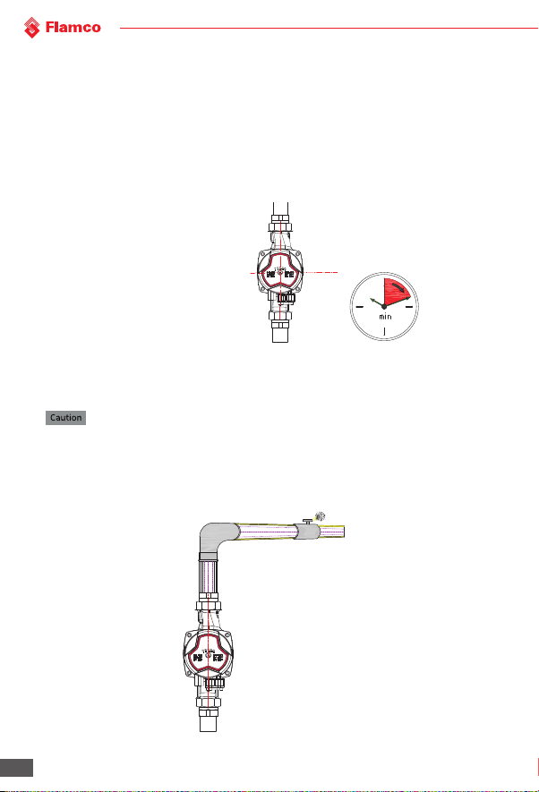
4.2 Position of Junction Box ............................................................................................................... 6
4.3 Position of junction box ................................................................................................................ 6
4.4 Thermal insulation of the pump body. ........................................................................................ 7
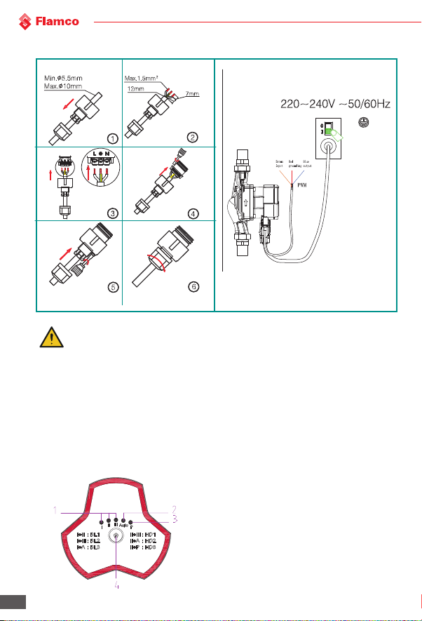
5� Electrical Connection ����������������������������������������������������������������������������������������������8
6� Control Panel����������������������������������������������������������������������������������������������������������8
6.1 Controls on Control Panel............................................................................................................. 8
6.3 Light area displaying the settings of the pump.... ....................................................................... 9
6.4 Button for selecting the pump settings........................................................................................ 9
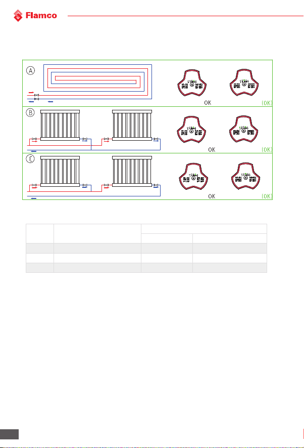
7� Setting of the pump�����������������������������������������������������������������������������������������������10
7.1 The pump should be set according to system type ...... ............................................................ 10
7.2 The control on the pump ............................................................................................................ 11
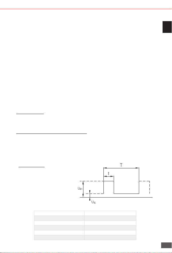
8� PWM Signal Control Mode �������������������������������������������������������������������������������������� 11
8.1 Control and Signal...... ................................................................................................................ 11
8.2 Interface....................................................................................................................................... 12
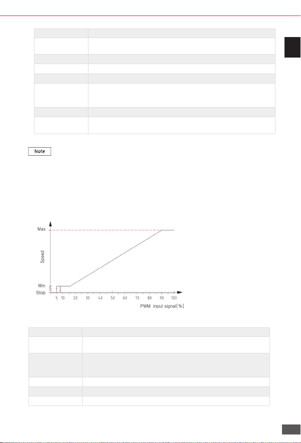
8.3 PWM Input Signal........ ................................................................................................................ 12
8.4 PWM PWM input signal profile PWM2(solar) .............................................................................. 13
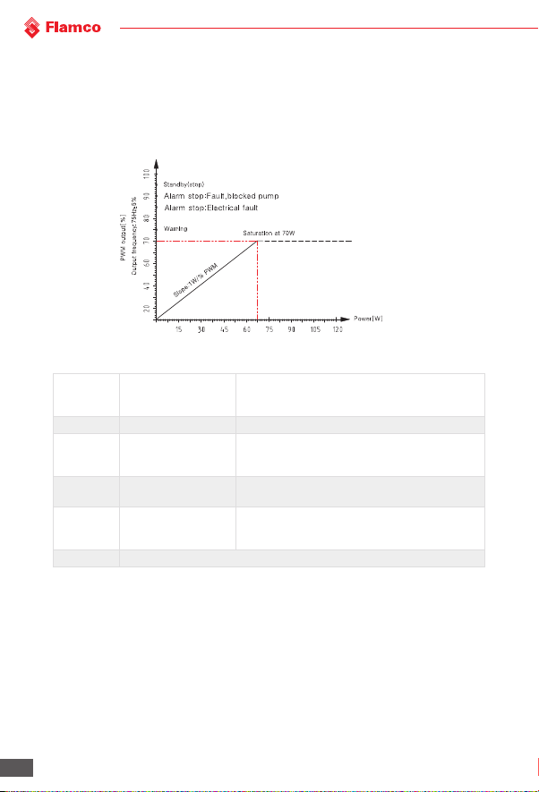
8.5 PWM Feedback Signal ................................................................................................................ 14
8.5 How to use the signals ................................................................................................................ 14
9� Bypass Valve��������������������������������������������������������������������������������������������������������� 15
9.2 Manually-operated bypass valve ............................................................................................... 15
9.3 Automatic bypass valve (temperature control type) .... ............................................................ 15
10� Start up��������������������������������������������������������������������������������������������������������������16
10.1 Before Start Up ......................................................................................................................... 16
10.2 Exhaust the Motor Pump........................................................................................................... 16
10.3 Gas-exhausting of heating system..... ...................................................................................... 16
11� Settings and performance of pump �����������������������������������������������������������������������17
11.1 Relationship between pump settings and its performance .................................................... 17
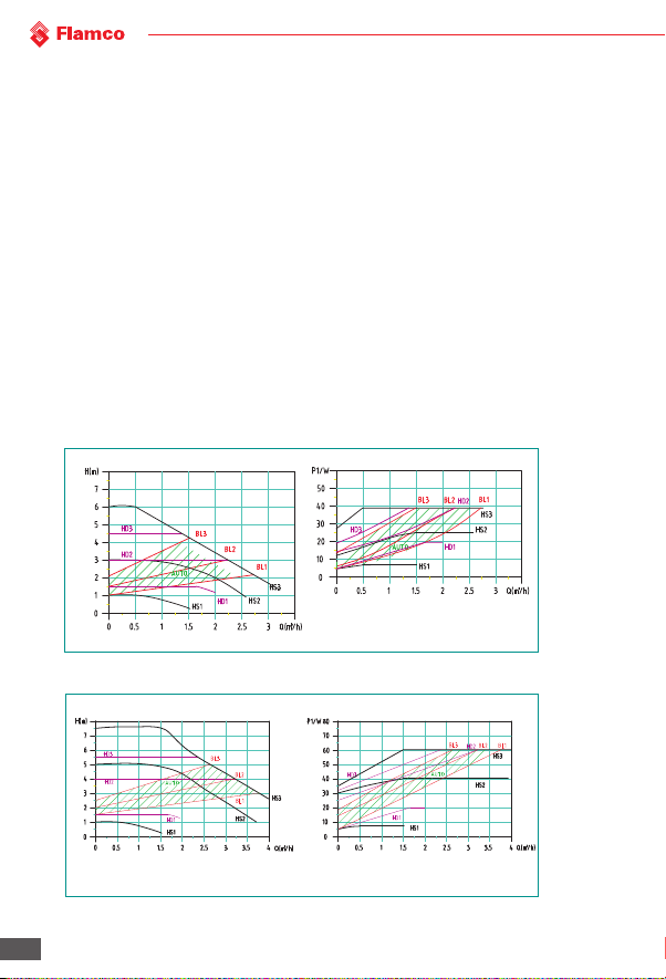
12� Performance Curve���������������������������������������������������������������������������������������������� 18
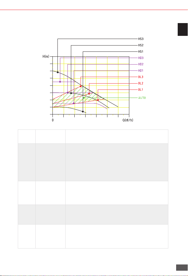
12.1 Performance curve guide ......................................................................................................... 18
12.2 Curve conditions....... ................................................................................................................ 18
12.3 Performance Curve... ................................................................................................................ 18
13� Characteristics����������������������������������������������������������������������������������������������������19
13.1 Description of nameplate.......................................................................................................... 19
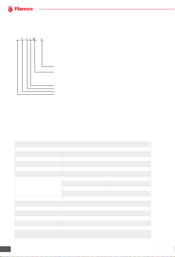
13.2 Model explanation.... ................................................................................................................ 20
14� Technical Parameters and Installation Dimensions�������������������������������������������������� 20
14.1 Technical data.. ......................................................................................................................... 20
14.2 Installation Dimensions............................................................................................................. 21
15� Fault checklist ���������������������������������������������������������������������������������������������������� 22

3
We reserve the right to change designs and technical specifications of our products.GPA III manual - 20211008
ENG
Notes
1. The installation manual should be read carefully before installation and use.
2. Any failure to comply with the content marked by safety warning marks may cause personal
injury, pump damage and other property loss, for which, the manufacturer shall not assume
any responsibility and compensation.
3. Installer, operator and user must comply with the local safety regulations.
4. The user must confirm that installation and maintenance of the product should be conducted by
sta proficient in the instructions and having professional qualification certificates.
5. Pumps must not be installed in damp environment or places that may be splashed by water.
6. In order to facilitate maintenance, one stop valve should be installed on each side of the pump
inlet and outlet respectively.
7. The power supply of pump should be cut o during installation and maintenance.
8. Pump with copper or stainless steel body should be adapted to the domestic hot water circulation.
9. The heat feed pipeline should not be supplemented with non-soened water frequently to avoid
an increase in the calcium in the circulating water of pipeline so as not to clog impellers.
10. It is prohibited to start the pump when there is no pumping liquid.
11. Some models can not be used for diet water.
12. Pumping liquid may be of high temperature and pressure, therefore, liquid in the system should be
drained o or stop valves on both sides of the pump must be switched o to avoid burns before
moving and removing pump.
13. In the summer or when the ambient temperature is high, attention should be paid to ventilation so
as to prevent moisture condensation and cause electrical fault.
14. In the winter, if the pump system does not operate or when the ambient temperature is below 0°C,
liquid in the pipeline system should be emptied to avoid causing frost crack to the pump body.
15. If the pump does not use for a long time, please turn o the conduit valves on pump inlet and outlet
ends and cut o the power of pump.
16. If he flexible cord is damaged, please connect service center to have it replaced together with the
connector.
17. If it is found that the motor is burning hot and abnormal, immediately turn o the valve on the pump
inlet end and cut o the pump power, besides, immediately contact your local dealer or service center.
18. If the pump failure can not be cleared in accordance with the description in the instructions,
immediately turn o the valve on the pump inlet end and cut o the pump power, besides,
immediately contact your local dealer or service center.
19. The product should be placed out of the reach of children, aer installation, isolation measures
should be taken to prevent children from touching.
20. The product should be placed in a dry, ventilated and cool place and stored at room temperature.
21. This appliance can be used by children aged from 8 years and above and persons with reduced
physical, sensory or mental capabilities or lack of experience and knowledge if they have been given
supervision or instruction concerning use of the appliance in a safe way and understand the hazards
involved. Children shall not play with the appliance. Cleaning and user maintenance shall not be
made by children without supervision.

4We reserve the right to change designs and technical specifications of our products.GPA III manual - 20211008
Warning : Before starting installation, the Installation and Operating Instructions of
device must be read carefully. Installation and use of the device must comply with local
regulations and follow good operation specification.
Warning : Personnel with physical decline, dysesthesia or poor mental ability and lacking
of experience and relevant knowledge (including children) should use the pump under
the supervision and guidance of people who can take charge of their safety.
1� Symbol description
Warning : Failure to comply with this security declaration will likely result in personal
injury !
Failure to comply with this security declaration will likely cause failure or damage to the
equipment !
Notes or instructions facilitating the work and ensuring operational safety.
2� Overview
2.1. GPA III series circulating pump for water circulation
(also called in abbreviation of “pump”) is mainly used for the water circulation in home heating
and domestic hot water system.
The pump is most suitable for the following :
• Stable heating system with variable flow
• Heating system with variable pipeline temperature
• Industrial circulation system
• Home heating and domestic water supply system
The pump is equipped with a permanent magnet motor and dierential pressure controller which
can adjust the performance of electric pump automatically and continuously to meet the actual
needs of the system.
The pump is equipped with control panel on the front, which is convenient for the operation of
users.
2�2� Advantages of installation of the pump
Easy installation and start-up
• The pump has auto-adaptation mode AUTO (factory settings). In most cases, you
can start the pump without need to make any adjustments and automatically
adjust it to meet the actual needs of the system.
• High comfort
• The running noise of pump and the whole system is low.
• Low energy consumption
• Compared with the conventional circulating pump, its energy consumption is very
low. The minimum energy consumption of the pump can reach 5W.

5
We reserve the right to change designs and technical specifications of our products.GPA III manual - 20211008
ENG
3� Service conditions
3.1. Ambient Temperature
Ambient temperature: 0°C~+70°C
3.2. Relative humidity (RH)
Max. humidity: 95%
3.3. Media (conveying liquid) temperature
Temperature of liquid conveying +2°C~+110°C. To prevent the control box and stator from appearing
condensate water, the temperature of pump conveying liquid must be always higher than the
ambient temperature.
3.4. System Pressure
The maximum is 1.0 MPa (10 bar).
3.5. Protection Level
The protection level is: I P 44
3.6. Inlet Pressure:
To avoid damage to the pump bearing caused by cavitation noise, the following minimum pressure
should be maintained in the pump inlet:
Liquid Temperature <75°C 90°C 110°C
Inlet Pressure 0.05 bar 0.5 bar 1.08 bar
0.5 m head 5 m head 10.8 m head
3.7. Pumping Liquid
Thin, clean, non-corrosive and non-explosive liquid does not contain any solid particles, fibers or
mineral oil; the pump should not be used for conveying flammable liquid such as vegetable oil and
gasoline absolutely. If the circulating pump is used for the case of high viscosity, the pump perfor-
mance will reduce, therefore, when selecting a pump, the viscosity of liquid must be considered.
4� Installation

6We reserve the right to change designs and technical specifications of our products.GPA III manual - 20211008
4.1 Installation
• Install the pump, arrows on the pump housing indicate the direction of liquid flowing
through the pump body.
• When the pump is installed on the pipeline, its inlet and outlet must be installed with two
leather packings provided.
• During installation, the pump sha must be in the horizontal position.
4.2 Position of Junction Box
4.3 Position of junction box
The junction box can rotate in 90°.To change the position of junction box, follow the operating
steps below:
1. Switch the valves of inlet and outlet and conduct decompression;
2. Loosen and remove the four socket head cap screws that fix the pump body;
3. Rotate the motor to the desired position and match the four screw holes;
4. Put the four socket head cap screws back and tighten them in the cross direction order;

7
We reserve the right to change designs and technical specifications of our products.GPA III manual - 20211008
ENG
5. Open the valve of inlet and outlet.
Warning : Pumping liquid may be of high temperature and pressure, therefore, liquid
in the system should be drained o or valves on both sides of the pump must be
switched o before removing socket head cap screws.
Change the position of junction box, the pump should not be started until the
system has been filled with pumping liquid or valves on both sides of the pump are
open.
4.4 Thermal insulation of the pump body
Restrict the thermal losses of the pump body and pipeline. Conduct thermal
insulation for the pump body and pipeline so as to reduce the thermal losses of
pump and pipeline.
Isolating or Caution covering junction box and control panel is not allowed.

8We reserve the right to change designs and technical specifications of our products.GPA III manual - 20211008
5� Electrical Connection
Electrical connection and protection should
be carried out in accordance with local
regulations.
Warning : The pump must be connected to earth wire. The pump must be connected with
an external power switch; the minimum gap between all the electrodes is 3mm.
• The pump does not need external motor protection.
• Check whether the voltage of power supply and frequency match with the parameters marked by
pump nameplate.
• Use the pump associated plug to connect power supply.
• If the indicator lamp on the control panel lights, it indicates that the power supply is switched on.
6� Control Panel
6.1 Controls on Control Panel
1.The pump I,II,III gear display
2.The pump automatic gearshi display (AUTO)
3.The pump PWM gear display
4.The pump gear shiing button

9
We reserve the right to change designs and technical specifications of our products.GPA III manual - 20211008
ENG
Special Note:
1.1. If I and II display at the same time, means BL1. If I and III display at the same time,If I and II display at the same time, means BL1. If I and III display at the same time,
means BL2. If I and Auto display at the same time, means Bl3.means BL2. If I and Auto display at the same time, means Bl3.
2.2. If II and III display at the same time, means HD1. If II and Auto display at the sameIf II and III display at the same time, means HD1. If II and Auto display at the same
time, means HD2. If II and P display at the same time, means HD3.time, means HD2. If II and P display at the same time, means HD3.
6.2 Fault code display status
Aer the power is turned on, position 6 light area displays the status. During operation, the gear
display light is on constantly. When the electric pump can not operate properly, the gear display
light will flash continuously, the corresponding faults are as shown below:
Fault code Fault description
Gear light 1flickers Over-voltage protection,restart aer voltage returns to normal (low
voltage protection value 270 +5V)
Gear light 2flickers Under-voltage protection,restart aer voltage returns to normal
(low-voltage protection value 165 + 5V)
Gear light 3flickers Over-current protection, restart aer 5S
Gear light 4flickers Under-load protection, restart aer 5S
Gear light 5flickers Over-Phase protection, r estart aer 5S
Gear light 1+2 flickers Locked-rotor protection, restart aer 5S
Gear light 1+3 flickers Start failure(asymmetric motor parameters),restart aer 5S
Gear light 1+4 flickers Over-heat protection, power reduced to half of the maximum
power, ambient temperature restored to the range of use, power
restored to the maximum.
Gear light 1+5 flickers Over-temperature protection, r estart aer environment
temperature restores to 5S in use range
If the fault is displayed, the power supply must be disconnected to facilitate Trouble shooting,
Aer trouble shooting, switch on the power supply again and re-start the electric pump.
6.3 Light area displaying the settings of the pump
The pump has 9 kinds of settings, which can be selected by buttons. The setting of the pump is
indicated by the light lit of 10 locations:
Key position Number of times of key Fixed light area Explanation
4
0AUTO Auto adaptation
1, 2, 3 BL1/BL2/BL3 Proportional pressure curve
4, 5, 6 HD1/HD2/HD3 Constant pressure curve
7, 8, 10 HS1/HS2/HS3 Constant speed curve
6.4 Button for selecting the pump settings
By pressing the button once at 2 seconds interval, the pump setting mode will change once. A
cycle is constituted of every nine presses on the button. For details, please refer to Section 6.3.

10 We reserve the right to change designs and technical specifications of our products.GPA III manual - 20211008
7� Setting of the pump
7.1 The pump should be set according to system type
Factory settings=AUTO (auto adaptation mode) Recommended and available settings of pump
Position System Type Settings of the pump
Optimal settings Or other optional settings
A Floor heating system AUTO HS3
B Dual pipeline heating system AUTO BL3
C Single pipeline heating system AUTO HS3
• AUTO (auto adaptation) mode shall adjust the pump performance automatically according
to the actual heat demand of system. Since performance is adjusted gradually, it is
recommended that leave it in the AUTO (auto adaptation) mode for at least a week before
changing the settings of pump.
• If you choose to change back to AUTO (auto adaptation) mode, the pump can remember the
set points of its previous AUTO mode and continue to adjust the performance automatically.
• Pump settings change from optimal settings to other optional settings, heating system is a
slow system, it is impossible to achieve optimal operation mode within several minutes or
hours. If the optimal settings of pump fail to achieve ideal heat distribution for each room, you
should change the pump settings to other settings.
• For the relationship between pump settings and performance curve, please see Section

11
We reserve the right to change designs and technical specifications of our products.GPA III manual - 20211008
ENG
7.2 The control on the pump
During the operation of pump, control it according to “proportional pressure control” (BL)
principle or “constant pressure control” (HD) principle.
In these two control modes, the performance of pump and corresponding power consumption
should be adjusted according to the heat demand of system.
7.2.1 Proportional pressure control
In this control mode, the pressure dierence on both ends of the pump shall be controlled by
flow. Proportional pressure curve in Q / H diagram is represented by BL1/BL2 /BL3(Section 11).
7.2.2 Constant pressure control
In this control mode, the pressure dierence on both ends of the pump remains constant, having
nothing to do with flow. In Q/H figure, constant pressure curve is a level performance curve,
represented by HD1/HD2 (Section 11).
8� PWM Signal Control Mode
8.1 Control and Signal
1) Control Principle
The pump is controlled by modulated LV PWM (Pulse Width Modulation) digital signal, which
means that the variance of velocity depends on the external input signal. The variance of velocity
is one of the functions of input control.
2) Digital LV PWM (Pulse Width Modulation) Signal
Design frequency scope of square wave PWM signal: 40Hz~4000Hz; PWM input signal (PWM IN)
is used to give velocity commands, and adjusts the velocity commands through adjusting PWM
duty cycle.
PWM output signal (PWM OUT) is the feedback signal of the pump, and the PWM frequency is
fixed at 75Hz
3) Duty Cycle (d%)
d%=t/T
For example:
T = 2 ms(500Hz)
t = 0.6 ms
d%=100×0.6/2=30%
UiH = 4~24V
UiL ≤ 1V
IiH ≤ 10mA
Code Descriptions
T Cycle
d Duty Cycle
UiH Input High Voltage
UiL Input Low Voltage
IiH wInput Current

12 We reserve the right to change designs and technical specifications of our products.GPA III manual - 20211008
8.2 Interface
The pump is controlled by
external electrical elements and
components through interfaces.
The interfaces convert external
signals into signals that can be
recognized by microprocessor
in the pump. In addition, when
the pump is supplied with 230V
voltage, the interfaces can
ensure that users will not be
at risk of high voltage electric
shock when contacting the
signal cable.
“Signal Ref” is a reference earthing, and it is not connected to protective earthing.
8.3 PWM Input Signal
• In area of high duty-cycle PWM signal, when the input signal fluctuates in the critical point,
there will be a delay area to prevent frequent stop and start of the pump.
• In area of low duty-cycle PWM signal, the pump runs at high velocity for the sake of system
safety. For instance, when the signal cable of gas boiler system is damaged, the pump will
continue to run at the maximum rotational speed and transfer heat through main heat
exchanger. This is also applicable to heat pump, ensuring continuous heat transfer in the case
of signal cable of pump is damaged and system safety is guaranteed.
• When PWM input signal is 0% or 100%, the pump will switch to non-PWM mode (normal
mode), and the default system will have no PWM signal input.

13
We reserve the right to change designs and technical specifications of our products.GPA III manual - 20211008
ENG
PWM Input Signal (%) Pump Status
0The pump switches to non-PWM mode (normal mode), and the default
system will have no PWM signal input.
<10 The pump runs at the highest velocity
10~84 The pump curve will drop from the highest to the lowest
85~91 The pump runs at the lowest velocity
91~95
If the velocity variance point of input signal fluctuates, then it will block
the start and stop of the pump according to the principle of magnetic
hysteresis
96~99 Stand-by, the pump stops
100 The pump switches to non-PWM mode (normal mode), and the default
system will have no PWM signal input.
This system is adaptive to the automatic switching of PWM and non-PWM mode. When
there is PWM signal input, the system will enter PWM mode.
8.4 PWM PWM input signal profile PWM2(solar)
• In area of low duty-cycle PWM2 signal, when the input signal fluctuates in the critical point,
there will be a delay area to prevent frequent stop and start of the pump.
• If it is necessary to switch to other control mode, please use manual button.
PWM Input Signal (%) Pump Status
≤5 Stand-by, the pump stops (The signal line is not connected with
PWM signal, and the water pump stops running)
>5/ ≤8
If the velocity variance point of input signal fluctuates, then it will
block the start and stop of the pump according to the principle of
magnetic hysteresis
>8/ ≤15 The pump runs at the lowest velocity
> 15/ ≤90 The pump curve will rise from the lowest to the highest
>90/ ≤100 The pump runs at the highest velocity

14 We reserve the right to change designs and technical specifications of our products.GPA III manual - 20211008
8.5 PWM Feedback Signal
PWM feedback signal can provide operation status of the pump, such as power loss or all kinds of
alarm/warning modes.
PWM feedback signal will feed back exclusive alarming information. If the power voltage detects
under voltage signal values, its output signal will be set to 75%. Provided sundries settlement exists
in the hydraulic system and causes rotor being blocked, the duty cycle of output signal is set to 90%,
the alarm will be given higher priority.
PWM
Output
Signal (%)
Pump Status Descriptions
95 Standby (stop) The pump stops
90
Alarm stops,
malfunctions (pump
blocked)
The pump does not work and will restarts only aer
trouble is addressed
85 Alarm stops, electrical
malfunction/trouble
The pump does not work and will restarts only aer
trouble is addressed
75 Warning
The pump runs, trouble has been detected under
this situation but it is not critical, and the pump can
still work.
0-70 0-70W (slope 1 W/% PWM)
8.5 How to use the signals
The signal can be used to measure power consumption of the pump. The pump signal can be used
to detect the actual operating point of the system rather than measuring by the current controlled
by the system. The signal is also applicable to comparing velocity setting value and feedback.
9� Bypass Valve

15
We reserve the right to change designs and technical specifications of our products.GPA III manual - 20211008
ENG
A bypass valve system is fitted between the inlet pipeline and return pipeline.
9.1 Use of bypass valve
Bypass valve
The role of bypass valve is: when all the valves in the floor heating circuit or the temperature control
valve of radiator are closed, it can be ensured that the heat from the boiler will be assigned.
Elements in the system:
• Bypass valve
• Flowmeter, position L.
The minimum flow must be ensured when all valves are closed. The pump settings depend on the
type of bypass valve it equipped with, i.e. manually-operated bypass valve or temperature-controlled
bypass valve.
9.2 Manually-operated bypass valve
Follow the following steps:
1. When adjusting the bypass valve, the pump should be in setting HS1 (constant speed gear I
mode). The minimum flow of system (Q min) must always be ensured. See the manual of bypass
valve manufacturer.
2. When the bypass valve has been adjusted, set the pump referring to Section 11 Pump Setting.
9.3 Automatic bypass valve (temperature control type)
Follow the following steps:
1. When adjusting the bypass valve, the pump should be in setting HS1 (constant speed gear I mode).
The minimum flow of system (Q min) must always be ensured. See the manual of bypass valve
manufacturer.
2. When the bypass valve has been adjusted, set the pump to the constant pressure mode. For the
relationship between pump settings and performance curve, please see Section 11. Settings
and
Performance of Pump.

16 We reserve the right to change designs and technical specifications of our products.GPA III manual - 20211008
10� Start up
10.1 Before Start Up
Before starting the pump, make sure that the system is filled with liquid, gas has been vented,
and the pump inlet pressure must achieve the minimum inlet pressure as required (see Chapter
3).
10.2 Exhaust the Motor Pump
The pump has automatic gas-
exhausting function. There is no
need for gas-exhausting before
startup. Gas in the pump may
cause noise.
The noise will disappear aer putting it into operation for a few minutes. Set the pump to be HS3
mode in a short time according to the size and structure of system, then gas in the pump will be
vented quickly. Aer gas exhausting of pump, that is, aer the noise disappears, set the pump
according to the recommended instructions. Please refer to Chapter 7.
The pump should not operate without water
10.3 Gas-exhausting of heating system

17
We reserve the right to change designs and technical specifications of our products.GPA III manual - 20211008
ENG
11� Settings and performance of pump
11.1 Relationship between pump settings and its performance
Setting Pump
Characteristics Functions
AUTO
(factory
settings)
Highest to
Lowest
Proportional
Pressure Curve
“Autoadaptation” function will automatically control the pump
performance within the specified range.
· Adjust the performance of the pump according to the size of
system;
· Adjust the performance of the pump according to the load
change of a period of time;
In the “Autoadaptation” mode, the pump is set to proportional
pressure control mode.
BL(1-3) Proportional
Pressure Curve
The pump working point will move up and down on the
proportional pressure curve according to the flow needs of
system, when the flow demand reduces, the pump pressure
supply will drop while when the flow demand increases, it
will rise.
HD(1-3) Constant
Pressure Curve
The pump working point will move back and forth on the
constant pressure curve according to the flow needs of system.
The pressure supply of pump remains
constant, having nothing to do with the flow demand.
HS(1-3) Constant
speed curve
Run on the constant curve at a constant speed. In speed H S (1-
3) mode, the pump is set to run on the maximum curve under
all working conditions.
Set the pump to HS3 mode in a short time, then gas in the
pump will be vented quickly.

18 We reserve the right to change designs and technical specifications of our products.GPA III manual - 20211008
12� Performance Curve
12.1 Performance curve guide
Each setting of the pump will have a corresponding performance curve (Q/H curve). While AUTO
autoadaptation mode covers a performance range. Input power curve (P1 curve) belongs to each
Q/H curve. Power curve represents the power consumption (P1) of pump in watts on the given
Q/H curve.
12.2 Curve conditions
The following description applies to the performance curves in GPA III series manual:
Testing liquid: gas-free water.
Applicable density of curve ρ = 983.2 kg/cubic meter, and the liquid temperature is +60°C .
• All the values expressed by curves are averages, they can not be taken as the guaranteed
curves. If a particular performance is required, measurement must be conducted separately.
Applicable kinematic viscosity of curve υ = 0.474 mm ² / s (0.474CcST)
12.3 Performance Curve
20
·GPAXX-4 III Performance curve
·GPAXX-5 III Performance curve
·GPAXX-6 III Performance curve
GPA III
21
·GPAXX-7 III Performance curve
·GPAXX-7.5 III Performance curve
13.Characteristics
13.1 Description of nameplate
GPA III

19
We reserve the right to change designs and technical specifications of our products.GPA III manual - 20211008
ENG
21
·GPAXX-7 III Performance curve
·GPAXX-7.5 III
Performance
curve
13.Characteristics
13.1 Description of nameplate
GPA III
13� Characteristics
13.1 Description of nameplate
21
·GPAXX-7 III Performance curve
·GPAXX-7.5 III Performance curve
13.Characteristics
13.1 Description of nameplate
GPA III
22
13.2 Model explanation
Pump model is consisted of upper Latin letters and Arabic numerals etc.,
whose meanings are as follows:
1
2
3
4
5
6
7
8
9
10
11
12
13
Maximum mode maximum power
Minimum mode minimum power
Maximum mode maximum current
Minimum mode minimum current
Power
Maximum pressure-bearing of system (Mpa)
Product No.
Motor steering
Voltage (V)
Insulation class
Protection Lever
Certification mark
Frequency (Hz)
Temperature grade
Energy efficiency label
Model
No. Explanation
Current
Type key example:GPA25-6B III 26 stands for a pump with nominal
diameter (DN)of suction and discharge ports of 25mm,maximum head
of 6m, and copper pump housing,third-generation products,with
functions of nine shifts+AUTO+PWM
GPA III
GPA
1. Power (max & min mode)
2. Current (max & min mode)
3. Maximum pressure bearing of system (Mpa)
4. Product No.
5. Motor steering
6. Voltage (V)
7. Insulation class
8. Protection Lever
9. Certification mark
10. Frequency (Hz)
11. Temperature grade
12. Energy eiciency label
13. Model

20 We reserve the right to change designs and technical specifications of our products.GPA III manual - 20211008
13.2 Model explanation
Pump model is consisted of upper Latin letters and Arabic numerals etc., whose meanings are
as follows:
22
13.2 Model explanation
Pump model is consisted of upper Latin letters and Arabic numerals etc.,
whose meanings are as follows:
1
2
3
4
5
6
7
8
9
10
11
12
13
Maximum mode maximum power
Minimum mode minimum power
Maximum mode maximum current
Minimum mode minimum current
Power
Maximum pressure-bearing of system (Mpa)
Product No.
Motor steering
Voltage (V)
Insulation class
Protection Lever
Certification mark
Frequency (Hz)
Temperature grade
Energy efficiency label
Model
No. Explanation
Current
Type key example:GPA25-6B III 26 stands for a pump with nominal
diameter (DN)of suction and discharge ports of 25mm,maximum head
of 6m, and copper pump housing,third-generation products,with
functions of nine shifts+AUTO+PWM
GPA III
GPA 29 : nine shis + AUTO (Head Integration Model)
28 : nine shi + AUTO + PWM (Head Integration Model)
27 : nine shis + AUTO
26 : nine shis + AUTO + PWM
function code
product series code
P : plastic pump housing
N : stainless steel pump housing
B : brass pump housing, vacancy stands for cast iron pump housing pumphousing material
maximum head (m)
nominal diameter (DN) of suction and discharge ports
A - class pipeline canned motor pump
Type key example:GPA25-6B III 26 stands for a pump with nominal diameter (DN)of suction and
discharge ports of 25mm,maximum head of 6m, and copper pump housing,third-generation
products,with functions of nine shis+AUTO+PWM
14� Technical Parameters and Installation Dimensions
14.1 Technical data
PH value of medium 6.5-8.5
Supply Voltage 220~240V, 50/60Hz
Motor Protection Pump does not need external protection
Protection Level IP44
Insulation Class H
Relative Humidity (RH) Max95%
System Load Bearing 1.0 MPa
Suction Inlet Pressure
Liquid Temperature Minimum Inlet Pressure
≤+75°C 0.005 Mpa
≤+ 90°C 0.028 Mpa
≤+ 110°C 0.100 MPa
EMC Standard EN61000-6-1 and EN61000-6-3
Sound Pressure level The sound pressure level of pump is lower than 42dB(A)
Ambient Temperature 0~+70°C
Temperature Grade TF110
Surface Temperature Maximum surface temperature should not exceed +125°C
Liquid Temperature +2~+110°C
To prevent the control box and stator from appearing condensate water, the temperature of
pump conveying liquid must be always higher than the ambient temperature
This manual suits for next models
15
Table of contents
Other flamco Water Pump manuals

flamco
flamco Flamcomat User manual

flamco
flamco Flamcomat MK-C G4 User manual

flamco
flamco Flamcomat Starter User manual

flamco
flamco 10 User manual

flamco
flamco Flamcomat MP G4 Remote User manual

flamco
flamco Meibes MeiFlow Top S MF User guide

flamco
flamco Flamcomat G4 User manual

flamco
flamco Flamcomat G4 User guide

flamco
flamco ENA 7 User manual
Popular Water Pump manuals by other brands

Wilo
Wilo Stratos-D Series Installation and operating instructions

Vogelsang
Vogelsang VX100Q operating instructions

Wilo
Wilo TOP-Z 20/4 EM Installation and operating instructions

BUSCH
BUSCH COBRA BA 0100 C instruction manual

TeichTip
TeichTip Sunsun CQB-2003 Operation manual

Sensidyne
Sensidyne Gilian 800i Quick start manual