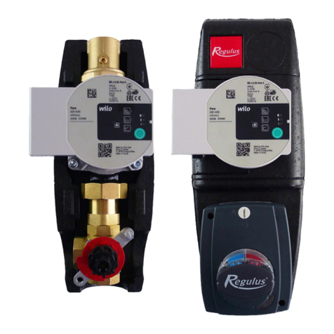
flamco Meibes MeiFlow Top S MF User guide

www.flamcogroup.com/manuals
MeiFlow Top S MF
GBR Installation and operating instuction

Manual MeiFlow Top S
2

We reserve the right to change designs and technical specifications of our products.
3
Abbreviation English
FL Flow line
RL Return line
FT Female thread
MT Male thread
Chap. Chapter
Pos. Position

Manual MeiFlow Top S
4

We reserve the right to change designs and technical specifications of our products.
5
GBR
Table of contents
1. Basic information.................................................................................................... 7
1.1 Safety instructions.............................................................................................................. 7
1.2 Intended use ...................................................................................................................... 9
1.2. Intended use....................................................................................................................................9
1.2.2 Improper use ....................................................................................................................................9
1.3 Device designation ............................................................................................................. 9
1.4 Residual hazards .............................................................................................................. 10
1.5 What to do in the event of breakdown or leaks .................................................................. 10
1.6 Spare and wear parts........................................................................................................ 10
1.7 Requirements on trained engineers .................................................................................. 11
2. Description and functions ...................................................................................... 12
2.1 Technical data .................................................................................................................. 12
2.2 Dimensions, using the example of 3-way manifold ............................................................ 14
2.3 Functions, using the example of 3-way manifold............................................................... 15
3. Installation and operation...................................................................................... 16
3.1 Installation ....................................................................................................................... 16
3.1.1 General installation instructions: ..................................................................................................16
3.1.2 Configuration and scope of delivery of wall bracket ....................................................................16
3.1.3 Adjustable wall clearance for wall bracket....................................................................................17
3.1.4 Installation of heating circuit manifold on the wall......................................................................17
3.1.5 Installation of pump groups on the heating circuit manifold ......................................................19
4. Commissioning and servicing ...................................................................................... 20

Manual MeiFlow Top S
6

We reserve the right to change designs and technical specifications of our products.
7
GBR
1. Basic information
Please follow these safety instructions carefully to eliminate hazards, personal injury and material
damage. The installation, commissioning, inspection, maintenance and servicing may only be
performed by an approved, specialist company. Please familiarise yourself with all the parts and
their handling before starting work. Observe all applicable safety regulations, environmental
regulations and legislation for the assembly, installation and operation of the system. In addition,
observe the applicable safety provisions of the DIN, EN, DVGW, VDI and VDE and all relevant country-
specific standards, laws and guidelines. When working on the system: Disconnect the system from
the mains and monitor it to ensure that no voltage is being supplied (e.g. at the separate cut-out
or a main switch). Secure the system against being restarted. Repairs to say components are not
permitted, these must be replaced. The installation location must be dry and frost proof. Be aware of
surround equipment and the local environment in relation to the safe operation of this equipment
Free access to the equipment is required.
Please also refer to the separately enclosed instructions from other manufacturers for additional
information (e.g. pumps, servomotors, controllers).
1.1 Safety instructions
Please follow these safety instructions carefully to prevent accidents and injury to persons and
property.
These operating instructions are primarily designed for the safe use and installation of the device
and make no claims to completeness.
These operating instructions describe the functionality of the device and are intended to provide
information about the required safety instructions and to draw attention to possible hazards.
These operating instructions are valid only for the described device and are not subject to the
manufacturer’s revision service. The sketches and drawings they contain are not to scale.
• Keep the operating instructions within easy reach of all employees instructed to carry out work on
the device so that they can refer to them as required.
• Keep the operating instructions in a clean, complete and legible condition throughout the entire
period of use.
• Read the operating instructions before working on the device for the first time and consult them
whenever uncertainties or doubts arise as to how the device should be handled.
• Should you come across any discrepancies when reading these operating instructions or should
anything remain unclear, please contact the manufacturer.

Manual MeiFlow Top S
8
Target group
These instructions are intended exclusively for authorised trained experts.
Only trained experts or installers authorised by the respective competent utility companies are
permitted to work on heating systems and domestic water, gas and electric circuits.
Regulations
When carrying out work, you must comply with:
- The statutory accident prevention regulations,
- The statutory environmental protection regulations,
- The German Employer's Liability Insurance Association regulations,
- The pertinent safety requirements of DIN, EN, DVGW, TRGI, TRF and VDE,
- ÖNORM, EN, ÖVGW-TR Gas, ÖVGW-TRF and ÖVE,
- SEV, SUVA, SVGW, SVTI, SWKI and VKF.
- and all region- or country-specific regulations and standards
Instructions for working on the system
- Disconnect the system from the mains and monitor it to ensure that no voltage is being supplied
(e.g. at the separate cut-out or a main switch).
- Secure the system against being restarted.
- WARNING! Risk of scalding at media temperature: > 60°C
Permissible mains supply und operating parameters
- heating side / primary side:
max. permissible operating pressure: 6 bar
- permissible operating temperature: 16-110°C (depending on pump)
- permissible ambient temperature: 5-50 °C (non-condensing)
- permissible media: heating water (in accordance with
VDI 2035, non-corrosive)
- The devices must be installed in enclosed, frost-free spaces
- any noise emissions or radiant heat from the station must be taken into account in the choice of
installation site
- observe the safety areas in accordance with EN 60529 when designing and installing the system
- prevent oxygen from entering the medium.

We reserve the right to change designs and technical specifications of our products.
9
GBR
1.2 Intended use
1.2. Intended use
All instructions in the operating instructions must be followed and the maintenance plan adhered to.
Any deviation from the intended use may cause hazards and is fundamentally not permitted.
The components listed in the following instructions are intended for use in heating systems
according to DIN EN 12828. The manifold is an optional system component that simplifies the
installation of a heat distribution system with several pump groups. Heating circuit groups (each
with the supply line on the right-hand side) are usually positioned on the top of the manifold. The
pipes of a heat generator are usually connected to the open lower connections. Additional lower
connections may be used as required, e.g. for additional heat generators, additional heating circuits,
buer tank, safety devices, etc.
1.2.2 Improper use
Improper use of the device of any kind may result in deviations from the specified performance data.
In particular, the following are not allowed:
• The use of liquids other than water with the described properties
• Use of the device without prior knowledge of the operating instructions
• Use of the device without legible warning and information signs
• Use of the device in a faulty condition
1.3 Device designation
Designation: MeiFlow Top S
Function: Manifold bar up to 70 kW
Type: MF
Manufacturer: Meibes System-Technik GmbH

Manual MeiFlow Top S
10
1.4 Residual hazards
The safety and warning information draws attention to residual hazards that cannot be avoided
due to the design and construction of the device. Please always observe the measures shown for
avoiding these hazards.
The device has been built according to the state of the art and in accordance with recognised safety
regulations.
The following residual hazards may occur during installation, commissioning, maintenance and
disassembly:
Warning: Risk of scalding from high media temperature
• Work particularly carefully.
• Use safety clothing (e.g. heat-resistant protective gloves).
• If necessary, surfaces must be thermally cleared before commencing work.
• Use stipulated tools.
Hazard: Risk of injury from electrical voltage
• Only instructed, qualified electricians are permitted to work on electrical equipment.
• Electrical installation spaces must always be kept locked.
1.5 What to do in the event of breakdown or leaks
• Close media lines using the appropriate valve.
• Contact a suitable trained expert or customer service of the manufacturer.
The device will only be released for operation again when the trained engineer has remedied the
fault and restored the device to its intended condition.
1.6 Spare and wear parts
All spare and wear parts used must correspond to the technical requirements defined by Meibes
System-Technik GmbH. This is guaranteed only with genuine spare parts. The manufacturer is not
liable for damage caused by the use of unapproved spare and wear parts or ancillary materials.

We reserve the right to change designs and technical specifications of our products.
11
GBR
1.7 Requirements on trained engineers
A trained expert has undergone advanced technical training and has suicient experience to
independently perform complicated tasks or work associated with residual hazards. Such experience
will in each instance refer to a specific specialism, e.g. maintenance, working on electrical systems,
systems mechanic for sanitary, heating and air conditioning technology. In preparation for
impending work, a trained expert must be able to correctly estimate the feasibility, risks and hazards
as well as the equipment required. A trained expert is expected to be able to understand complex,
minimally prepared plans and descriptions, and to obtain missing and required detailed information
by suitable means.
The trained expert must be able to restore and check the intended condition of a system.
A worker can be a trained expert in several fields.
For work on the electrical equipment, only electrically skilled persons according to DGUV regulation
3 may be used.

Manual MeiFlow Top S
12
2. Description and functions
2.1 Technical data
Heating circuit manifold including wall brackets, either hydraulically separated or with low
dierential pressure
for max. number of heating circuits 3 5 7
Connection pairs at top 2 3 4
Connection pairs at bottom 2 3 4
Total width (E) 500 mm 750 mm 1000 mm
Clearance of bracket (F) 250 mm 500 mm 750 mm
Upper connections (heating circuit) 1 1/2" FT (union nut)
Lower connections (heat generator / boiler guard, heating circuit) choice between 1 ½″ MT or FT (flat sealing, half-shell technology 2x open,
remainder closed with caps)
Clearance between supply and return line 125 mm
Material - manifold Steel (interior untreated, exterior primed: black or orange)
Material for removable insulation EPP
max. temperature of heat transfer medium 110°C
permissible positive operating pressure: 6 bar
Kvs value approx. 15 (-> 0.04 bar primary at 3 m³/h)
Nominal flow rate / power 3 m³/h / 70 kW (at 20K spread)

We reserve the right to change designs and technical specifications of our products.
13
GBR

Manual MeiFlow Top S
14
2.2 Dimensions, using the example of 3-way manifold

We reserve the right to change designs and technical specifications of our products.
15
GBR
2.3 Functions, using the example of 3-way manifold
Pos. Designation Description
(1) thermal insulation Robust insulation shells with locking mechanism minimise the heat losses. Wall installation brackets
(included in delivery) surround the insulation. The bracket is thermally separated and acoustically
insulated.
(2) Identification of the hydraulically
connected areas
The connections which are hydraulically connected to one another inside are colour coded.
(3) Choice of male or female thread The lower connections are fitted with removable half-shells with 1 ½" male thread. A union nut
(female thread) can also be used on the flanged connections in place of the half-shells.
(4) Blind caps Two of the lower connections are only fitted with the half-shells described under (3). The remaining
2, 4 or 6 lower connections are also capped with a union nut including a suitable metal washer. The
connections that are capped for delivery can be used as a connection with a 1 ½" male or female
thread as required.
Depending on the connection configuration, it is possible to change the position of the supply and
return flow accordingly.
Note on low dierential pressure variant: (primed in orange)
Service use includes heat generators with built-in pump.
In this case, the flow and return lines are hydraulically connected to one another by two internal
openings.
Connections, dimensions and outputs as with the hydraulically separated manifold bar (primed in
black).

Manual MeiFlow Top S
16
3. Installation and operation
3.1 Installation
3.1.1 General installation instructions:
• Suicient space for installation, maintenance and service
• Tighten all screw fittings if necessary during a pressure test or following the initial heating
3.1.2 Configuration and scope of delivery of wall bracket
Legend:
(1) Wall bracket for heating circuit manifold bar up to 70 kW
(2) Countersunk Allen bolt M6x10 ISO10642, 10N
(3) adjustable internal brackets U-profiles
(4) Rawlplugs 10x50
(5) Washer 8.4x16x1.6 DIN 125, galvanised steel
(6) Hex. bolt 8x50 DIN 571, galvanised steel

We reserve the right to change designs and technical specifications of our products.
17
GBR
3.1.3 Adjustable wall clearance for wall bracket
Two-stage Pos. A or B
Pos. A) For wall clearance of thermal insulation 29 mm and axial distance from the wall: 96.5 mm
Pos. A) For wall clearance of thermal insulation 68 mm and axial distance from the wall: 135.5 mm
For other dimensions: see chapter 2.2
3.1.4 Installation of heating circuit manifold on the wall
We recommend first securing the manifold with the corresponding wall brackets (included with
delivery) and screwing on the pump groups without additional fixings.
Securing the pipes also secures the system against tilting.
Alternatively, the manifold can be secured to the fastened pump groups without needing its own
wall bracket. The pump groups and pipework must be fastened appropriately to ensure they are
capable of taking the weight and other loads.
Note: With greater manifold wall clearances, later (de)installation of the rear insulation shells of the
Meibes pump groups is correspondingly easier.

Manual MeiFlow Top S
18
Installation steps, using the example of 3-way manifold:
1.) Attach wall brackets to the wall, taking dimensions in Chap. 2 into account.
2.) Set the clearance to the wall by adjusting the internal brackets (see also Chap. 3.1.2)
3.) Insert the manifold bar with insulation into the mounting
4.) Fix manifold bar in place by tightening the remaining internal brackets
5.) Connect the hydraulics, observing the correct assignment of FL/RL connecting pieces

We reserve the right to change designs and technical specifications of our products.
19
GBR
3.1.5 Installation of pump groups on the heating circuit manifold
The pump group is installed on the flat sealing screw fittings of the heating circuit manifold. Secure
the manifold appropriately to ensure it is capable of taking the weight of the pump groups.
Caution: This is only possible if the lower insulation shell can be attached aerwards from the rear.
The combination with our heating circuit manifold provides suicient distance from the wall.)
Installation steps:
1.) Remove the supply and return line from the rear insulation shell
- extend with additional accessories as required (e.g. screw fittings, heat flow meter)
2.) Screw the pump group with flat gaskets to the installed manifold.
3.) Fit the piping to the connections.
4.) Attach the lower insulation shell from the rear
5.) Lock the central insulation shell in place on the lower shell and attach the front insulation
with cover
Hydraulic connection with application example
View of possible use:
In most cases, heating circuit pump groups
with the supply line on the right-hand side are
used. In specific circumstances, heating circuit
pump groups with the supply line on the le-
hand side simplify installation. The choice is
achieved by assigning the connections below
(see hydraulically connected areas). The supply
and return lines must be connected to the
correspondingly identified connectors on the
manifold.
* Radiator heating circuit with FL on le-hand
side
** Return riser (wood boiler) & corresponding
buer tank
*** Conventional heating boiler

Manual MeiFlow Top S
20
4. Commissioning and servicing
1. Check the leak tightness of the system
2. Flush, fill and bleed the pipework (with filling water in accordance with VDI 2035)
Operation:
Please note the application limits:
• see Chap. 1
Maintenance:
We recommend performing regular leak-tightness tests.
Table of contents
Other flamco Water Pump manuals
flamco
flamco Flamcomat G4 User manual
flamco
flamco Flamcomat MK-C G4 User manual

flamco
flamco GPAIII Series User guide
flamco
flamco Flamcomat Starter User manual

flamco
flamco Flamcomat User manual
flamco
flamco ENA 7 User manual
flamco
flamco Flamcomat MP G4 Remote User manual
flamco
flamco 10 User manual

flamco
flamco Flamcomat G4 User guide
Popular Water Pump manuals by other brands
Grundfos
Grundfos Unilift AP12 Installation and operating instructions

SPX
SPX Johnson Pump Viking Power 16 instruction manual
KSB
KSB Etanorm-RX Installation & operating manual

Grundfos
Grundfos UP instructions

Grundfos
Grundfos Redi-Flo4 Installation and operating instructions

EINHELL
EINHELL GH-DP 3730 Original operating instructions

