FLARM ATOM UAV User manual

ATOM UAV MANUAL
Date: 2021-10-28
Version: 1.1
Page: 1 of 35
FLARM Technology Ltd
Hinterbergstrasse 15
CH-6330 Cham
Document Number:
FTD-088
Document status
Published status
Confidentiality status
☐Draft
☒Released
☐Canceled
☐Internal
☐NDA
☒Public
Version control
Ver.
Date
Summary of changes
1.0
2021-10-04
Initial version
1.1
2021-10-28
Adapt maximum antenna gain for FCC compliance

ATOM UAV MANUAL
Date: 2021-10-28
Version: 1.1
Page: 2 of 35
FLARM Technology Ltd
Hinterbergstrasse 15
CH-6330 Cham
Document Number:
FTD-088
Table of contents
1Introduction ...................................................................................... 4
2General Overview .............................................................................. 5
2.1 Specifications.......................................................................... 5
2.2 System Description .................................................................. 6
2.2.1 Abbreviations............................................................ 8
3Installation........................................................................................ 9
3.1 Housing ................................................................................. 9
3.2 Supplying Power...................................................................... 9
3.3 Antennas................................................................................ 9
3.3.1 RF Connectors..........................................................10
3.3.2 Placement ...............................................................10
3.4 Data Interfaces ......................................................................12
3.4.1 JST GH Connector.....................................................12
3.4.2 TFM Connector .........................................................12
3.4.3 USB Connector.........................................................13
3.5 Status LEDs...........................................................................13
4Configuration and Maintenance ....................................................... 15
4.1 Configuration .........................................................................15
4.1.1 FLARM ....................................................................15
4.1.2 Wi-Fi & Bluetooth .....................................................17
4.1.3 Configuration Lock ....................................................17
4.1.4 Remote ID...............................................................18
4.1.5 MAVLink..................................................................18
4.2 Firmware Updates...................................................................19
4.3 Traffic Monitor........................................................................19
4.4 Support Package Download ......................................................19
4.5 Factory Reset.........................................................................19
5Interfaces........................................................................................ 21
5.1 MAVLink Interface...................................................................21
5.1.1 Integration with PX4 .................................................21
5.1.2 External Navigation Source ........................................22
5.1.3 Compatible Ground Control Software ...........................23
ATOM UAV MANUAL
Date: 2021-10-28
Version: 1.1
Page: 3 of 35
FLARM Technology Ltd
Hinterbergstrasse 15
CH-6330 Cham
Document Number:
FTD-088
5.2 JSON Interface.......................................................................23
6Mandatory Firmware Update ........................................................... 24
7Packing List ..................................................................................... 25
7.1 Atom UAV .............................................................................25
7.2 Atom UAV OEM ......................................................................25
8Recommended Accessories.............................................................. 26
9Troubleshooting and Servicing Information .................................... 27
10 Warranty Information and Terms of Use ......................................... 28
11 Release Notes.................................................................................. 29
11.1 FLARM Hub............................................................................29
11.1.1 Version 1.3.4 (66ebbfe4) ...........................................29
11.1.2 Version 1.3.2 (804f5880)...........................................29
11.2 FLARM Atom ..........................................................................29
11.2.1 Version 7.0.5 (421df442f) ..........................................29
12 Conformity Declarations .................................................................. 30
12.1 FCC Compliance Statement ......................................................30
12.2 ISED Compliance Statement.....................................................31
12.3 Supplier's Declaration of Conformity ..........................................32
Appendix A –List of Error Codes ........................................................... 33
Appendix B - End User License Agreement (EULA) ................................ 34

ATOM UAV MANUAL
Date: 2021-10-28
Version: 1.1
Page: 4 of 35
FLARM Technology Ltd
Hinterbergstrasse 15
CH-6330 Cham
Document Number:
FTD-088
1Introduction
Atom UAV is a FLARM device developed specifically for UAVs. Leveraging the Atom
platform, it is a miniature, feature-packed device that can be used standalone as
an add-on or retrofit or integrated into other designs.
Highlights:
Based on the FLARM Atom System-on-Chip platform
Full, worldwide FLARM interoperability
Cortex-M4F processing core
Integrated Wi-Fi and Bluetooth module
72-channel u-blox GNSS engine
Web app for configuration and diagnostics
1090MHz receiver for ADS-B and rebroadcast (TIS-B/ADS-R)
Barometric sensor for pressure altitude
Consolidated, unified traffic stream on JSON or MAVLink
Direct broadcast remote ID, compliant with ASTM F3411-19, EC 2019/945, EC
2020/1058
Atom UAV is available in two functionally equivalent variants:
Atom UAV: For standalone use, housed in a plastic enclosure, using a JST GH
connector for power supply and data streaming, and an integrated Wi-Fi
antenna. Ships with a complete set of antennas and cables.
Atom UAV OEM: Board only, for embedded use with a board-to-board data
connector and RF connectors for using dedicated antennas. Does not contain
the antennas or cables.
ATOM UAV MANUAL
Date: 2021-10-28
Version: 1.1
Page: 5 of 35
FLARM Technology Ltd
Hinterbergstrasse 15
CH-6330 Cham
Document Number:
FTD-088
2General Overview
2.1 Specifications
Atom UAV
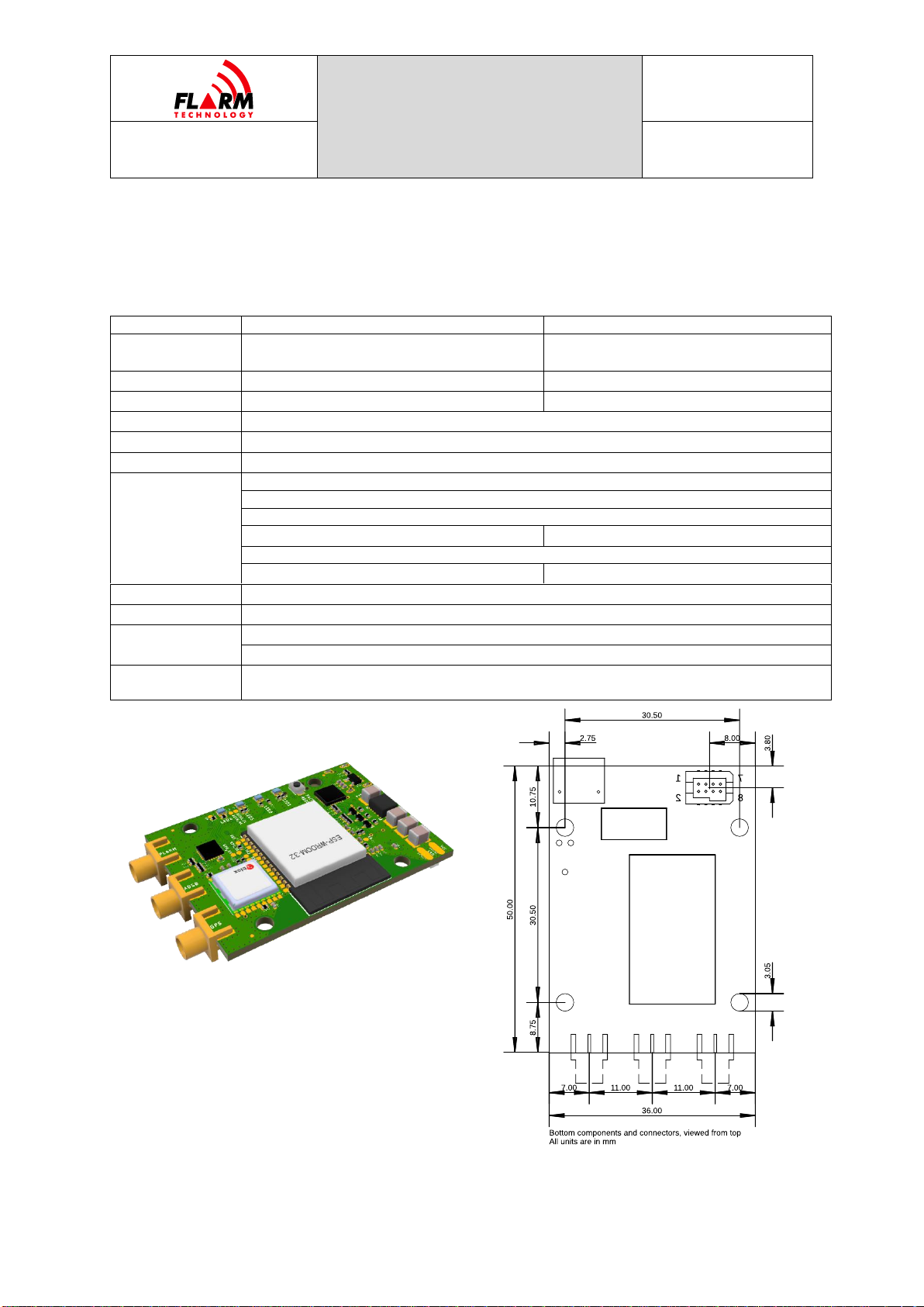
Atom UAV OEM
Dimensions
57x40x15 mm
(54x40x15 mm w/o connectors)
57x36x10 mm
(50x36x8 mm w/o connectors)
Mass
43 g
15 g
Mounting
N/A
4x3 mm holes, 30.5mm grid
Platform
FLARM Atom System-on-Chip
Navigation
u-blox 8th generation multi-GNSS receiver
Storage
32 MB NOR FLASH, microSD card slot
Connectors
FLARM Radio: MCX
ADS-B Receiver: MCX
GNSS: MCX
N/A (internal antenna)
Wi-Fi: U.FL
USB-C (power, virtual serial)
JST GH 6-pin
TFM-104-02-L-D 8-pin B2B
Protocols
JSON, MAVLink
User Interface
4 LED status (bicolor)
Power Supply
5-28 VDC (JST GH/TFM)
5 VDC (USB-C)
Power
Consumption
1.4 W typical

ATOM UAV MANUAL
Date: 2021-10-28
Version: 1.1
Page: 6 of 35
FLARM Technology Ltd
Hinterbergstrasse 15
CH-6330 Cham
Document Number:
FTD-088
2.2 System Description
FLARM is the collision avoidance system and traffic awareness/electronic
conspicuity technology used by General Aviation, light aircraft, and UAVs. It was
designed to support self-separation for both VFR and IFR in applicable airspace
classes. Aircraft with a FLARM system alert the pilots when on a collision course
with another aircraft. Like TCAS/TAS, visual and aural warnings indicate that a
collision is imminent, requiring the pilots to act. However, unlike TCAS, FLARM
does not issue Resolution Advisories (RA), so pilots need to select the appropriate
course of action themselves.
FLARM works by calculating and broadcasting its own predicted future 3D flight
path to nearby aircraft, using a digital radio channel. At the same time, it receives
the future flight path from surrounding aircraft.
The system determines its position, altitude, and movement with a sensitive GNSS
receiver. Based on those and other parameters, a precise projected flight path can
be calculated. The flight path, together with additional information such as an
identification number, is encoded before being broadcast over an encrypted radio
channel twice per second. Flight models are available for most aircraft types,
including piston-engine airplanes, jets, helicopters, gliders, hang gliders,
paragliders, UAVs, etc.
FLARM was invented in 2004 following an increasing number of mid-air collisions.
Research and accident investigations had shown that the see-and-avoid principle
was insufficient to reliably detect approaching aircraft in time. It initially spread in
the domain of non-powered aircraft but was soon followed by rapid expansion in
powered airplanes and helicopters. Over 50,000 manned aircraft and many more
UAVs already have a FLARM-system installed. In Europe, more than 50% of all
General Aviation aircraft have FLARM (including nearly 100% of gliders). The
technology has additionally spread to other parts of the world and is today also
used most prominently in North and South America, Australia, New Zealand, South
Africa, Israel, and some Asian countries.
Atom UAV is a FLARM device for installation in UAVs. It is based on the latest Atom
SoC platform and features a web app called FLARM Hub. Atom UAV has been
designed for worldwide use and connects to a range of flight computers.
Configuration is simple through the web interface.
Atom UAV has a fully functional FLARM radio for receiving and transmitting traffic
information, an ADS-B / Mode-S transponder receiver, and a modern GNSS
receiver, as well as a Wi-Fi/Bluetooth radio for configuration and
transmission/reception of Remote ID messages. This enables aircraft that are not
yet equipped with FLARM to also be detected by Atom UAV.
ATOM UAV MANUAL
Date: 2021-10-28
Version: 1.1
Page: 7 of 35
FLARM Technology Ltd
Hinterbergstrasse 15
CH-6330 Cham
Document Number:
FTD-088
As a transmitter, UAVs mounted with Atom UAV are visible by other FLARM-
equipped devices and can be tracked by Remote ID receivers. As a receiver, it can
receive and process FLARM, ADS-B and Remote ID signals from surrounding
aircraft that are made available on the digital data interface on the JST or USB
interface in various formats.
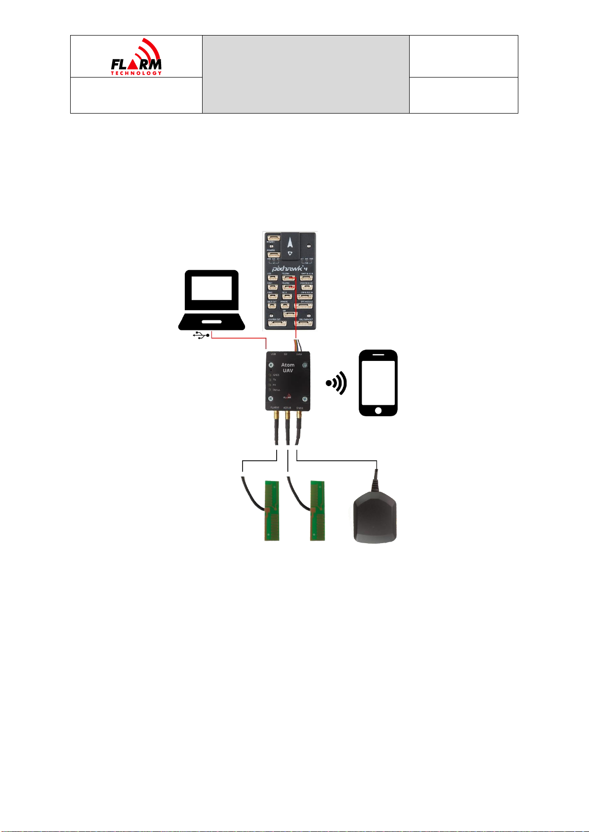
The diagram above shows a typical setup. Atom UAV is connected to a Pixhawk /
PX4 flight controller, with a data interface and power supply. Optionally, power can
be supplied through USB. Two FLARM/ADS-B antennas are connected to the FLARM
and ADS-B RF connectors. A GNSS antenna is connected to the GNSS RF
connector.
Internally, the device contains two microcontrollers. The Atom SoC runs the FLARM
radio protocol. The periphery processor runs FLARM Hub and provides connectivity
via Wi-Fi, USB and the JST/TFM connector. Both processors require individual
firmware updates.

ATOM UAV MANUAL
Date: 2021-10-28
Version: 1.1
Page: 8 of 35
FLARM Technology Ltd
Hinterbergstrasse 15
CH-6330 Cham
Document Number:
FTD-088
2.2.1 Abbreviations
Abbreviation
Meaning/Explanation
ADS-B
Automatic Dependent Surveillance —Broadcast
GNSS
Global Navigation Satellite System
GPS
Global Positioning System (NAVSTAR)
ISM
The ISM radio band (≈915 MHz)
RF
Radio Frequency/Radio
SoC
System-on-Chip
SRD860
The SRD860 radio band (≈868 MHz)
SSID
Service Set Identifier, (Wi-Fi network name)
SSR
Secondary Surveillance Radar
TAS
Traffic Advisory System
TCAS
Traffic alert and Collision Avoidance System
UAV
Unmanned Aerial Vehicle
UI
User Interface

ATOM UAV MANUAL
Date: 2021-10-28
Version: 1.1
Page: 9 of 35
FLARM Technology Ltd
Hinterbergstrasse 15
CH-6330 Cham
Document Number:
FTD-088
3Installation
3.1 Housing
Mount Atom UAV to a suitable mounting location. The orientation of the device is
discretionary. The housing is not waterproof, and ingress of solid particles and
liquids must be avoided. Should the device get moist, it must be completely dried
prior to further use. If the device becomes wet, it may be permanently damaged
and rendered unusable. Should the device be suddenly cooled, this may result in
the formation of condensation.
3.2 Supplying Power
Atom UAV has two interfaces for power supply:
USB connector with 5V (DC)
JST/TFM connector 5-28V (DC)
The chosen cables must be of sufficient diameter to carry the power (1.4 W).
3.3 Antennas
The FLARM system uses a radio communication frequency in the SRD860 band
(≈868 MHz) or in an ISM band (≈915 MHz) in different parts of the world. Atom
UAV will automatically select the applicable frequency based on the GNSS position.
The following frequencies are used within the specified areas.
Area
Frequency
Europe
868.2 –868.4 MHz
North America
902.2 –927.8 MHz
The antennas should be selected for the frequency band applicable in the
geographic area where the aircraft is being operated. Often, such antennas only
cover one band and need to be selected carefully. However, the antennas shipped
with the Atom UAV standalone variant (and listed as suggested accessories in
Section 7) have wide band characteristics and cover the FLARM frequency bands
of all regions, as well as the ADS-B band. Inappropriate antennas, especially
antennas when placed at poor locations, can provide poor system performance.
Note: Atom UAV OEM ships without antennas. The integrator must carefully
select appropriate antennas. Atom UAV will not automatically detect
inappropriate or damaged antennas, including antennas for the wrong
frequency band.

ATOM UAV MANUAL
Date: 2021-10-28
Version: 1.1
Page: 10 of 35
FLARM Technology Ltd
Hinterbergstrasse 15
CH-6330 Cham
Document Number:
FTD-088
Note: Communication between FLARM devices employs an encrypted, patent-
protected protocol. Any unlicensed use, copying, distribution, conversion,
replication, access, interception, de-compiling, reverse engineering, or
further transmission of knowledge so acquired relating to the system
components or software/firmware, in whole or in part, is thus illegal.
3.3.1 RF Connectors
Atom UAV uses MCX connectors for all RF interfaces. The corresponding connector
can be identified as GNSS, ADS-B and FLARM on the device housing (Atom UAV
standalone variant) or on the PCB next to the connectors (Atom UAV OEM variant).
The Atom UAV OEM variant additionally has a U.FL connector for a Wi-Fi antenna.
3.3.2 Placement
For good performance of the FLARM system, the FLARM antenna must be placed
at least 20 mm from larger pieces of conductive materials such as a metal surface.
The FLARM antenna must be installed vertically (perpendicular to the horizontal
plane).
If the aircraft body contains large amounts of conductive materials such as carbon
fiber, the antenna must be placed outside the vehicle body. If the selected antenna
location does not give clear line of sight in all horizontal directions, two Atom UAV
devices can be mounted to increase the coverage, using the radio diversity
functionality described later in this document.
For good performance of the GNSS receiver, the GNSS antenna must be placed
such that signals from the sky are not obstructed. The antenna should be mounted
on a sufficiently large ground plane, either as part of the host PCB or on a separate
metal plane that adds more than 20 mm of ground around the antenna.
Due to the larger transmit power of the ADS-B system, the placement is less
crucial. However, the antenna should also be installed vertically and be placed at
a sufficient distance from conductors.
Note: Atom UAV also receives and decodes Mode-S signals, which do not contain
position information. Instead, the distance is estimated from the received
signal strength. The radiation pattern of the ADS-B antenna installed on
the aircraft should be omnidirectional to give accurate range information.
Due to limitations in the MAVLink protocol, Mode-S targets are not
available on this interface.
ATOM UAV MANUAL
Date: 2021-10-28
Version: 1.1
Page: 11 of 35
FLARM Technology Ltd
Hinterbergstrasse 15
CH-6330 Cham
Document Number:
FTD-088
The Wi-Fi system has two functional modes. The first mode is the FLARM Hub web
application for configuration. In that case, the antenna selection and placement
are not crucial, since the device needs to only cover short ranges.
The second mode is for Remote ID. In that case, for the Atom UAV OEM variant,
an antenna with sufficient gain must selected as described in Section 8. The
antenna must be installed vertically and placed in a location that allows for
omnidirectional radiation characteristics, i.e., without conductors in the vicinity.
When using Remote ID with the Atom UAV standalone variant, the internal Wi-Fi
antenna is used to transmit Wi-Fi NAN packets. In that case it is recommended to
place the device vertically such that the omnidirectional plane of the internal
antenna is aligned with the horizontal plane.
For more general information on the placement of FLARM antennas, please see
document FTD-041

ATOM UAV MANUAL
Date: 2021-10-28
Version: 1.1
Page: 12 of 35
FLARM Technology Ltd
Hinterbergstrasse 15
CH-6330 Cham
Document Number:
FTD-088
3.4 Data Interfaces
The Atom UAV standalone variant is mounted with a JST GH connector to facilitate
connection to popular flight controllers. Atom UAV OEM variant is mounted with a
TFM connector for ease of integration as a component into larger systems. The
basic functionality is the same with both variants.
3.4.1 JST GH Connector
The Atom UAV standalone variant is equipped with a GH connector from JST
1
. It
exposes a 3.3 V UART interface and may be used to supply power. The pin
assignment is shown in the table below.
Table: JST-GH Pinout
Pin
Function
Function Alt
1
Vin 5–28 V
2
TXD UART (Out)
3
RXD UART (In)
4
CANbus TX (Out)
GPIO
5
CANbus RX (In)
GPIO
6
GND
When connecting to a Pixhawk or similar flight controller, the
RX and TX lines must be crossed, i.e., TX of the flight
controller must be connected to RX of the Atom UAV, etc.
The JST GH receptacle is surface mounted to the board; thus,
the mechanical stability is limited. Do not put force on the
solder connections!
3.4.2 TFM Connector
The Atom UAV OEM variant is equipped with a TFM-104-02 board-to-board
connector. The corresponding connector for the main board is the equivalent SFM
connector. The table below shows the pin assignment.
Table: TFM-104-02-L-D Pinout
Pin
Function
Function Alt
1
Vin 5–28 V
2
TXD UART (Out)
3
DO NOT CONNECT
4
RXD UART (In)
5
DO NOT CONNECT
6
CANbus TX (Out)
GPIO
1
https://jst.de/product-family/show/89/gh
ATOM UAV MANUAL
Date: 2021-10-28
Version: 1.1
Page: 13 of 35
FLARM Technology Ltd
Hinterbergstrasse 15
CH-6330 Cham
Document Number:
FTD-088
7
GND
8
CANbus RX (In)
GPIO
3.4.3 USB Connector
The unit may be powered through the USB connector. This is mechanically less
robust and thus not recommended in flight in any type of aircraft. For validation
of the functionality however it provides a simple method for power and data
connectivity.
The Atom UAV uses an CP2102 USB chip. The Virtual COM Port (VCP) drivers
2
must
be installed on the host computer to use this feature. In Windows, use the “Device
Manager”
3
to see what COM-port is used.
3.5 Status LEDs
On the Atom UAV standalone variant, the status LED functionality is described on
the device housing. On the Atom UAV OEM variant, the LEDs are numbered from
LED1 to LED4 on the PCB. The functionality of the LEDs is as follows:
LED1: GNSS reception
LED2: FLARM radio transmitting
LED3: FLARM radio receiving
LED4: Status
Each LED can be either GREEN, AMBER, RED, or OFF. The different states have
the following meaning, depending on whether the device is in bootloader mode or
if the application has booted, indicated by the four multicolor LEDs:
2
Download from: https://www.silabs.com/developers/usb-to-uart-bridge-vcp-drivers
3
In Windows, press the “Windows” key and X together, then M

ATOM UAV MANUAL
Date: 2021-10-28
Version: 1.1
Page: 14 of 35
FLARM Technology Ltd
Hinterbergstrasse 15
CH-6330 Cham
Document Number:
FTD-088
GNSS
Transmit
Receive
Status
Initialization
————
————
————
————
Non-fatal error
————
————
————
————
Fatal error
————
————
————
————
Nominal state, no GPS
fix
————
————
————
————
Nominal state, 3D GPS
fix, transmitting
————
————
————
————
Nominal state, 3D GPS
fix, transmitting and
receiving at least one
aircraft
————
————
————
————
The LED lights are also visualized in FLARM Hub on the Status page.

ATOM UAV MANUAL
Date: 2021-10-28
Version: 1.1
Page: 15 of 35
FLARM Technology Ltd
Hinterbergstrasse 15
CH-6330 Cham
Document Number:
FTD-088
4Configuration and Maintenance
Atom UAV can be configured via the HUB web interface. It runs its own Wi-Fi access
point to which e.g., a mobile phone or laptop computer can connect. The SSID of
the Wi-Fi is set to the (complete) Device ID as printed on the label, e.g.,
FLATMUAVW-000042 when the serial number is 42. The default password is
“password”. Please make sure to change when configuring the device.
Note: On the Atom UAV OEM variant, the Wi-Fi module comes with a U.FL
connector instead of an PCB antenna. An antenna must be connected for
proper operation. If not, the range might be insufficient for a reliable
connection to operate the Web Interface.
Once connected to the Wi-Fi, open the address http://10.10.10.10 in a browser of
the device that is connected to the Atom UAV. The web interface should now load.
On the Status page, the connectivity, system information and GNSS fix are shown.
4.1 Configuration
The different configuration pages can be used to configure FLARM, the Wi-Fi and
Bluetooth interfaces, and FLARM Hub. In the sections below, important aspects
and additional information is given to each of the configuration items.
4.1.1 FLARM
Explanations for each field are available as a tooltip by hovering over or clicking
on the question mark next to each field.
When a configuration item is changed (selecting a dropdown item, radio button,
or moving focus away from a text field), the configuration is automatically applied
to FLARM. No additional step is necessary to apply the value. A successful change
of the configuration item is indicated as a green border around, and a green
checkmark inside, the field. An incorrect value is indicated as a red border around
the field with a red exclamation mark inside.
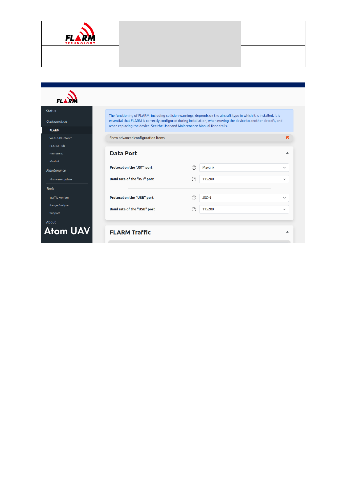
4.1.1.1 Port Configuration
The protocol and baud rate can be configured independently for the JST and USB
ports. There is a choice between JSON and MAVLink for the JST port, and JSON for
the USB port. If desired, output on either one or both ports can be deactivated.
ATOM UAV MANUAL
Date: 2021-10-28
Version: 1.1
Page: 16 of 35
FLARM Technology Ltd
Hinterbergstrasse 15
CH-6330 Cham
Document Number:
FTD-088
Please note that the default on the JST port is MAVLink, and output on the USB
port is deactivated.
For more information on the host settings for the MAVLink interface, please refer
to Section 5.1. For more information on the JSON interface, please see Section
5.2.
4.1.1.2 Radio Diversity
Atom UAV supports radio diversity by using two devices concurrently. This
facilitates achieving sufficient radio coverage in larger airframes with RF
shadowing, e.g., due to large carbon fiber bodies or battery assemblies. In such a
setup, both devices will emit the same ID (and thus be seen as one aircraft by
other receivers) while ignoring signals transmitted by each other.
Diversity can be configured on the web interface under “Configuration”, “FLARM”,
“Radio Diversity”. It requires defining a primary and a secondary device, where
the secondary is explicitly linked to the primary through a reference (part of the
serial number).
In normal operation, i.e., a device that is not as part of a primary/secondary setup,
choose the “No diversity” option. This is the default.
ATOM UAV MANUAL
Date: 2021-10-28
Version: 1.1
Page: 17 of 35
FLARM Technology Ltd
Hinterbergstrasse 15
CH-6330 Cham
Document Number:
FTD-088
To use radio diversity, configure both the primary and secondary. Inappropriate or
incomplete configuration may lead to loss of function or multiple targets being
transmitted from the same vehicle.
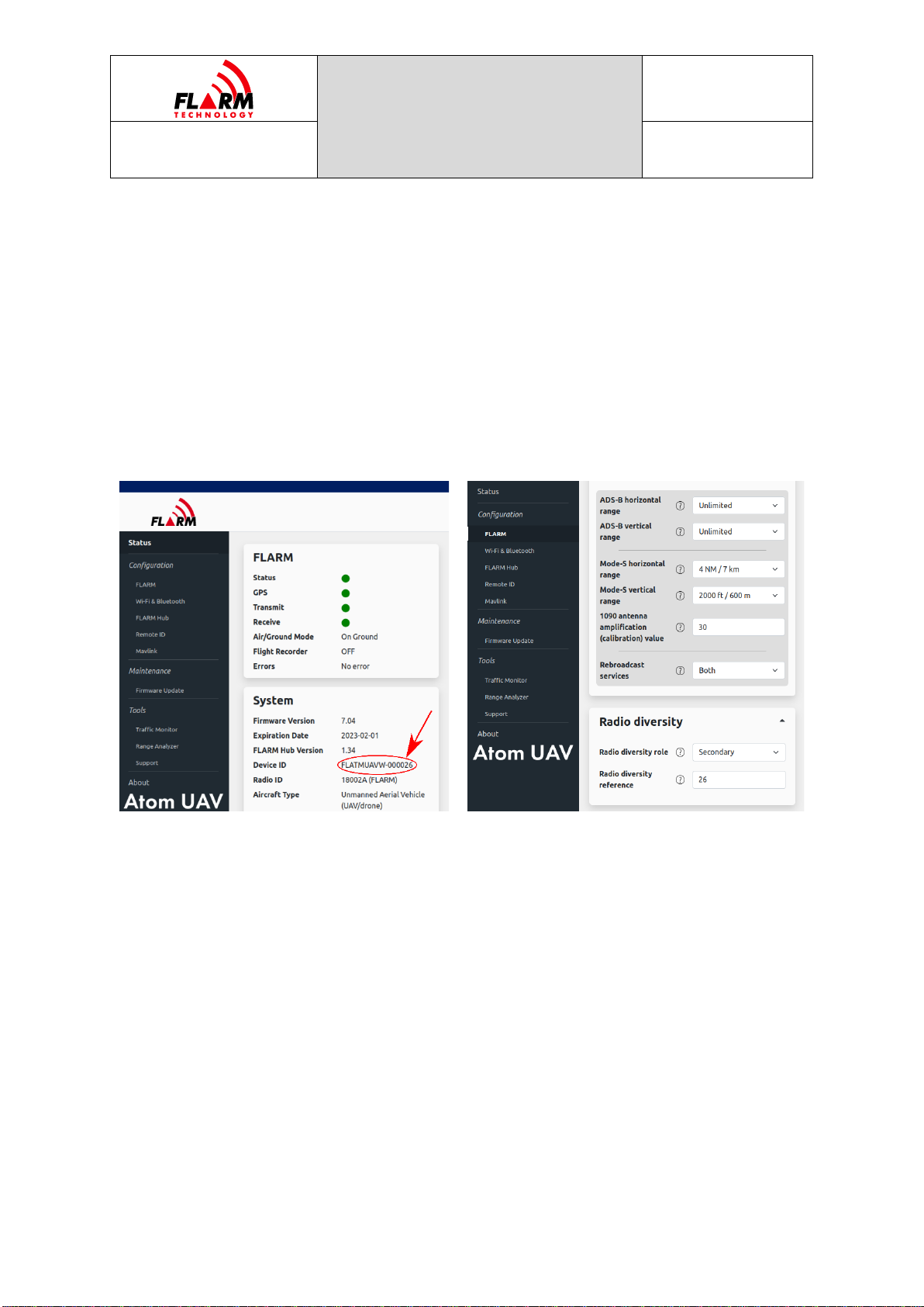
The secondary device requires the reference to the primary device. This reference
is the serial number of the primary device, as can be found on the sticker on the
device or in the web interface, on the “Status” page, under “System”, “Device ID”,
e.g., 26 for the primary with the Device ID FLATMUAVW-000026.
Note: Only devices of the same type can be used in a diversity setup. Specifically,
the OEM variant cannot be mixed with the standalone variant.
Identification of serial number in primary device
Setting radio diversity role in secondary device
4.1.2 Wi-Fi & Bluetooth
Wi-Fi and Bluetooth settings and network names can optionally be changed, e.g.,
to make it easier to identify a particular device. The default password (“password”)
must be changed during initial configuration.
Wireless connectivity (Wi-Fi and Bluetooth) can be disabled under configurable
conditions (in-flight, with valid GPS, or after specific elapsed time since power-on).
4.1.3 Configuration Lock
To prevent unauthorized persons from modifying the configuration, the
configuration can be locked by a password. Set a password that is different from
the Wi-Fi password. Users will still be able to access FLARM Hub but will not be
able to change the locked configuration items.

ATOM UAV MANUAL
Date: 2021-10-28
Version: 1.1
Page: 18 of 35
FLARM Technology Ltd
Hinterbergstrasse 15
CH-6330 Cham
Document Number:
FTD-088
4.1.4 Remote ID
Atom UAV allows to transmit in accordance with ASTM F3411-19/DIN EN 4709-
002, EC 2019/945, EC 2020/1058. The device emits all information through the
Wi-Fi NAN standard and needs to be activated to operate.
The standards allow for multiple types of identifiers. The identifier can be either
based on the Atom UAV serial number (e.g., when used as an “Add-On”), a CAA
registration ID which is validated by the device, or an UTM-assigned UUID.
The other configuration items follow the ASTM and DIN standards, some of which
are optional, depending on the region. Atom UAV implements the full stack of
messages and gives users the option to set all values according to regulations.
Note: Please refer to the local civil aviation authority or legislation to ensure the
requirements are fulfilled.
Note: Atom UAV requires the user to set the correct and valid entries in each
configuration field.
Messages are transmitted immediately after bootup, even if no position is
available. The messages are emitted at a 1 Hz rate using the Wi-Fi NAN message
format. The take-off location is determined as the first available fix. It is therefore
recommended to only power up the Atom UAV at the takeoff location.
Remote ID messages are received only when the transmit function is activated as
well.
Note: The functionality of Remote ID on Atom UAV requires the wireless module
to be enabled (‘Wireless Auto Shut Off’ disabled in Section 4.1.2)
4.1.5 MAVLink
A separate configuration page is available for all functionality related to the
MAVLink integration. Atom UAV supports using an external GNSS solution provided
through the MAVLink interface. For more details on the setup and requirements on
the host, please refer to Section 5.1.
The ports status block on the configuration page shows which port has been
configured through MAVLink, and if Atom UAV receives a heartbeat message
(“Connected”is true). For reference, the System and Component IDs are shown.
Furthermore, a packet counter allows to quickly diagnose the MAVLink data link.
For the configuration of a systematic offset between the GNSS source (e.g., PX4)
and the Atom UAV, a configuration item is available. The procedure is described in
Section 5.1.2.2. The “Timepulse offset valid”flag shows if both Atom UAV and host

ATOM UAV MANUAL
Date: 2021-10-28
Version: 1.1
Page: 19 of 35
FLARM Technology Ltd
Hinterbergstrasse 15
CH-6330 Cham
Document Number:
FTD-088
(e.g., PX4) have a valid fix and time reference, and the “Measured timepulse
offset”shows the difference in the time pulse in milliseconds.
4.2 Firmware Updates
The Atom UAV is equipped with two microcontrollers and thus needs two firmware
files to operate. The Atom chip firmware running the FLARM protocol has an
expiration date and needs to be updated annually.
The update process is as follows. On the navigation bar of the page, go to
“Maintenance”, “Firmware Update”. To update the Atom with a new Atom
Firmware, a .fw file is needed. To update FLARM Hub, a .bin file is needed.
4.3 Traffic Monitor
The traffic monitor displays traffic received by Atom UAV, using symbology like
TCAS. It does not issue collision warnings. Targets for all received types of signals
are shown.
The traffic monitor can be used e.g., to troubleshoot connectivity and configuration
issues. It should not be used for collision avoidance purposes. When on the ground,
aircraft with elevated privacy settings (Stealth or No Track mode enabled, Random
ID selected) will not be shown.
When using the traffic monitor, note the zoom level and vertical axis reference
(North Up or Track Up).
4.4 Support Package Download
FLARM Hub can create a zip file containing configuration and debug data. The
button to create the zip file can be found on the Tools / Support page. The zip file
is saved on the connected computer or mobile device.
Note: The package creation and download take approximately 10 minutes to
complete, during which the device will be inoperable.
4.5 Factory Reset
A factory reset can be triggered by holding the button pressed while powering up
the device (hold for at least 1s).

ATOM UAV MANUAL
Date: 2021-10-28
Version: 1.1
Page: 20 of 35
FLARM Technology Ltd
Hinterbergstrasse 15
CH-6330 Cham
Document Number:
FTD-088
The following items are reverted to factory default:
FLARM configuration
FLARM Hub configuration
Wi-Fi SSID and password
Bluetooth name
The firmware versions (Atom and Hub) do not change.
Other manuals for ATOM UAV
1
This manual suits for next models
1
Table of contents
Other FLARM Industrial Equipment manuals


