FLARM FUSION PowerFLARM Operating instructions

POWERFLARM
FUSION USER AND
MAINTENANCE
MANUAL
Date: 2020-11-10
Version: 1.0
Page: 1 of 49
FLARM Technology Ltd
Hinterbergstrasse 15
CH-6330 Cham
Document Number:
FTD-078

POWERFLARM
FUSION USER AND
MAINTENANCE
MANUAL
Date: 2020-11-10
Version: 1.0
Page: 2 of 49
FLARM Technology Ltd
Hinterbergstrasse 15
CH-6330 Cham
Document Number:
FTD-078
Document Status
Published status
Confidentiality status
☐
Draft
☒Released
☐
Canceled
☐
Internal
☐NDA
☒
Public
Version Control
Ver.
Date
Summary of changes
1.0
2020-11-10
Initial version
Scope and Summary
This manual serves as the maintenance manual for the PowerFLARM Fusion
installation, as well as the Instructions for Continued Airworthiness (ICA), unless
replaced by an ICA as part of the Minor Change Approval or STC in applicable
parts.
This manual also describes the user interfaces of PowerFLARM Fusion, for both
pilots and maintenance personnel. This includes the FLARM Hub web app, Wi-Fi
and Bluetooth interfaces, LEDs, and the USB port.
In addition, this manual contains general advice on operation of FLARM for pilots.
For specific instructions for operating the FLARM displays, see the relevant
display manual.

POWERFLARM
FUSION USER AND
MAINTENANCE
MANUAL
Date: 2020-11-10
Version: 1.0
Page: 3 of 49
FLARM Technology Ltd
Hinterbergstrasse 15
CH-6330 Cham
Document Number:
FTD-078
Table of contents
1General Overview .............................................................................. 6
1.1 System Description .................................................................. 8
1.2 Definitions.............................................................................. 9
1.2.1 Abbreviations............................................................ 9
1.2.2 Terminology.............................................................10
1.3 Housing ................................................................................10
1.3.1 Connections and Cabling ............................................10
1.3.2 Status LEDs and Startup ............................................11
1.3.3 Factory Reset...........................................................12
1.4 Displays ................................................................................14
1.5 Radio Communication and Antennas ..........................................14
1.6 Additional Documents..............................................................15
1.7 Document Revisions................................................................15
2Limitations ...................................................................................... 16
3FLARM Hub ...................................................................................... 17
3.1 Connection ............................................................................17
3.2 General Web Interface Guidance ...............................................19
3.3 Status Page ...........................................................................20
3.3.1 FLARM ....................................................................20
3.3.2 System ...................................................................21
3.3.3 Time & Location .......................................................21
3.3.4 Obstacle Database ....................................................22
3.3.5 Wi-Fi ......................................................................22
3.4 Configuration .........................................................................22
3.4.1 FLARM ....................................................................22
3.4.2 Wi-Fi and Bluetooth ..................................................23
3.4.3 FLARM Hub Settings ..................................................23
3.4.3.1 Device Lock ............................................. 23
3.4.3.2 Language Selection................................... 23
3.5 Firmware and Obstacle Updates ................................................23
3.6 IGC file download ...................................................................24
3.7 Traffic Monitor........................................................................24

POWERFLARM
FUSION USER AND
MAINTENANCE
MANUAL
Date: 2020-11-10
Version: 1.0
Page: 4 of 49
FLARM Technology Ltd
Hinterbergstrasse 15
CH-6330 Cham
Document Number:
FTD-078
3.8 Interactive Data Port...............................................................24
3.9 Range Analyzer ......................................................................24
3.10 Support Package Download ......................................................25
4USB Flash Drive Operation............................................................... 26
5Configuration................................................................................... 27
5.1 Essential Settings ...................................................................27
5.2 Obstacle Databases.................................................................28
6FLARM Operations ........................................................................... 29
6.1 FLARM Displays ......................................................................29
6.1.1 Status and Error Conditions........................................29
6.2 Traffic Collision Warnings .........................................................29
6.2.1 ADS-B and Mode-S Traffic ..........................................30
6.3 Obstacle Collision Warnings......................................................30
6.4 Alert Zones............................................................................31
6.5 Traffic Information..................................................................32
6.6 Radio Range ..........................................................................32
7IGC Flight Recorder ......................................................................... 33
8Wi-Fi and Bluetooth Data Usage ...................................................... 34
8.1 ICD on Wi-Fi, TCP ...................................................................34
8.2 ICD on Wi-Fi, WebSocket .........................................................34
8.3 ICD on Bluetooth ....................................................................34
8.4 GDL 90 .................................................................................35
8.5 Apps.....................................................................................35
9Annual Maintenance ........................................................................ 37
9.1 Mandatory Firmware Update.....................................................37
9.2 Obstacle Database Update .......................................................38
10 Pre-flight Inspection ....................................................................... 39
11 Troubleshooting and Servicing Information .................................... 40
12 Removal, Replacement, and Addition of components ...................... 41
13 Additional Information .................................................................... 42
13.1 Warranty Information and Terms of Use .....................................42

POWERFLARM
FUSION USER AND
MAINTENANCE
MANUAL
Date: 2020-11-10
Version: 1.0
Page: 5 of 49
FLARM Technology Ltd
Hinterbergstrasse 15
CH-6330 Cham
Document Number:
FTD-078
13.2 Conformity Declarations ..........................................................42
13.3 Installation of Mode-S Transponder or ADS-B Out Equipment.........43
Appendix A – Annual Maintenance Checklist ......................................... 44
Appendix B – List of Error Codes ........................................................... 46
Appendix C – End User License Agreement (EULA) ............................... 48

POWERFLARM
FUSION USER AND
MAINTENANCE
MANUAL
Date: 2020-11-10
Version: 1.0
Page: 6 of 49
FLARM Technology Ltd
Hinterbergstrasse 15
CH-6330 Cham
Document Number:
FTD-078
1General Overview
FLARM is the collision avoidance system and traffic awareness/electronic
conspicuity technology used by General Aviation, light aircraft, and UAVs. It has
been designed to support self-separation for both VFR and IFR in applicable
airspace classes. Aircraft with a FLARM system alert the pilots when on a collision
course with another aircraft. Similar to TCAS/TAS, visual and aural warnings
indicate that a collision is imminent, requiring the pilots to take action. However,
unlike TCAS, FLARM does not issue Resolution Advisories (RA), so pilots need to
select the appropriate course of action themselves.
FLARM works by calculating and broadcasting its own predicted future 3D flight
path to nearby aircraft. At the same time, it receives the future flight path from
surrounding aircraft. An intelligent motion prediction algorithm calculates a
collision risk for each aircraft based on an integrated risk model.
The system determines its position, altitude, and movement with a sensitive
GNSS/GPS receiver. Based on those and other parameters, a precise projected
flight path can be calculated. The flight path, together with additional information
such as an identification number, is encoded before being broadcast over an
encrypted radio channel twice per second. Flight models are available for most
aircraft types, including piston-engine airplanes, jets, helicopters, gliders, hang
gliders, paragliders, UAVs, etc.
PowerFLARM Fusion also incorporates an ADS-B and transponder (SSR) Mode-S
receiver. This enables aircraft that are not yet equipped with FLARM to also be
detected and included in the collision prediction algorithm.
FLARM was invented in 2004 following an increasing number of mid-air collisions.
Research and accident investigations had shown that the see-and-avoid principle
was insufficient to reliably detect approaching aircraft in time. It initially spread in
the domain of non-powered aircraft but was soon followed by rapid expansion in
powered airplanes and helicopters. Over 50,000 manned aircraft and many more
UAVs already have a FLARM-system installed. In Europe, more than 50% of all
General Aviation aircraft have FLARM (including nearly 100% of gliders). The
technology has additionally spread to other parts of the world and is today also
used most prominently in North and South America, Australia, New Zealand, South
Africa, Israel, and some Asian countries.
In addition to annunciating collision warnings, many FLARM systems can also show
nearby aircraft on a radar-like screen (CDTI). Similar to the use of weather radar
to avoid thunderstorms, this can be helpful for short to medium term strategic
planning in high traffic density situations.

POWERFLARM
FUSION USER AND
MAINTENANCE
MANUAL
Date: 2020-11-10
Version: 1.0
Page: 7 of 49
FLARM Technology Ltd
Hinterbergstrasse 15
CH-6330 Cham
Document Number:
FTD-078
FLARM can also warn about fixed obstacles like masts and power lines. Obstacle
collision warnings are based on an optionally installed database, which needs to
be kept up to date.
FLARM systems are available from many different manufacturers under different
product names. A system normally consists of a remotely installed FLARM device,
a panel-mounted FLARM Compatible display, one or two externally mounted
FLARM antennas, and internally mounted GNSS and ADS-B/SSR antennas. There
are also portable FLARM devices available (usually with an integrated display), as
well as FLARM systems integrated into other avionics (e.g. EFIS-systems).
FLARM is approved by EASA and others for installation in certified aircraft and is
recommended by many aviation authorities and organizations. The installation is
normally a minor change and can be done by any competent maintenance
organization. Several General Aviation airports have started requiring FLARM for
all aircraft. FLARM is also mandatory in France for gliders and a similar requirement
for light powered aircraft is under investigation.

POWERFLARM
FUSION USER AND
MAINTENANCE
MANUAL
Date: 2020-11-10
Version: 1.0
Page: 8 of 49
FLARM Technology Ltd
Hinterbergstrasse 15
CH-6330 Cham
Document Number:
FTD-078
1.1 System Description
PowerFLARM Fusion is a modern FLARM device for installation in General Aviation
aircraft. It is based on the latest PowerFLARM technology and features a novel web
app called FLARM Hub. PowerFLARM Fusion has been designed for worldwide use
and connects to a range of displays, including tablet apps via Wi-Fi or Bluetooth.
A FLARM system consists of several parts. PowerFLARM Fusion, or Fusion for
short, contains the collision computer, radio circuitry, and peripheral
communication subsystems. It is powered from the aircraft electrical system and
connects to the following equipment and parts:
One or two FLARM antennas. Installed antennas can be either external or
internal. The choice depends on the antenna function and aircraft type.
External antennas are mounted outside the aircraft fuselage (normally on
top and below the aircraft). Internal antennas are mounted inside the aircraft
fuselage (e.g. in the cockpit or in gliders also in the vertical stabilizer). The
use of two antennas (antenna diversity) allows for an improved coverage.
A 1090 ADS-B/SSR antenna (optional) for receiving Mode-S and ADS-B
signals.
A GPS antenna used by Fusion to determine its trajectory.

POWERFLARM
FUSION USER AND
MAINTENANCE
MANUAL
Date: 2020-11-10
Version: 1.0
Page: 9 of 49
FLARM Technology Ltd
Hinterbergstrasse 15
CH-6330 Cham
Document Number:
FTD-078
A panel mount USB socket with extension cord for a USB flash drive.
At least one FLARM Compatible display. These displays have been certified
or validated to have implemented all essential functions.
A number of complementary displays or accessories, parsing the FLARM data
stream.
An audio panel for feeding aural warnings into the aircraft’s audio system
(optional).
An Electronic Flight Bag (EFB) or navigation app running on a mobile device
(tablet or phone), connected through Wi-Fi or Bluetooth.
A web browser running FLARM Hub on a computer or mobile device.
1.2 Definitions
1.2.1 Abbreviations
Abbreviation
Meaning/Explanation
ADC
Analog-to-Digital Converter
ADS-B
Automatic Dependent Surveillance — Broadcast
AIRAC
Aeronautical Information Regulation And Control
AMP
Aircraft Maintenance Program
CARP
Continuous Analyzer of Radio Performance
CDTI
Cockpit Display of Traffic Information
EEPROM
Electrically Erasable Programmable Read-Only Memory
EFB
Electronic Flight Bag
EFIS
Electronic Flight Instrument System
GNSS
Global Navigation Satellite System
GPIO
General-Purpose Input/Output
GPS
Global Positioning System (NAVSTAR)
ICA
Instructions for Continued Airworthiness
ICD
Interface Control Document
IFR
Instrument Flight Rules
ISM
The ISM radio band (≈915 MHz)
PIC
Pilot In Command
RF
Radio Frequency/Radio
SRD860
The SRD860 radio band (≈868 MHz)
SSID
Service Set Identifier, (Wi-Fi network name)
SSR
Secondary Surveillance Radar
TAS
Traffic Advisory System
TCAS
Traffic alert and Collision Avoidance System
UAV
Unmanned Aerial Vehicle
UI
User Interface
VFR
Visual Flight Rules
VMC
Visual meteorological conditions
POWERFLARM
FUSION USER AND
MAINTENANCE
MANUAL
Date: 2020-11-10
Version: 1.0
Page: 10 of 49
FLARM Technology Ltd
Hinterbergstrasse 15
CH-6330 Cham
Document Number:
FTD-078
1.2.2 Terminology
The words shall and must are used to indicate a mandatory requirement.
The word should is used to indicate a recommendation, meaning that there may
exist valid reasons in particular circumstances not to follow a specific item, but the
full implications must be understood and carefully weighed before choosing a
different course.
The word may is used to indicate that an item is truly optional.
1.3 Housing
1.3.1 Connections and Cabling
POWERFLARM
FUSION USER AND
MAINTENANCE
MANUAL
Date: 2020-11-10
Version: 1.0
Page: 11 of 49
FLARM Technology Ltd
Hinterbergstrasse 15
CH-6330 Cham
Document Number:
FTD-078
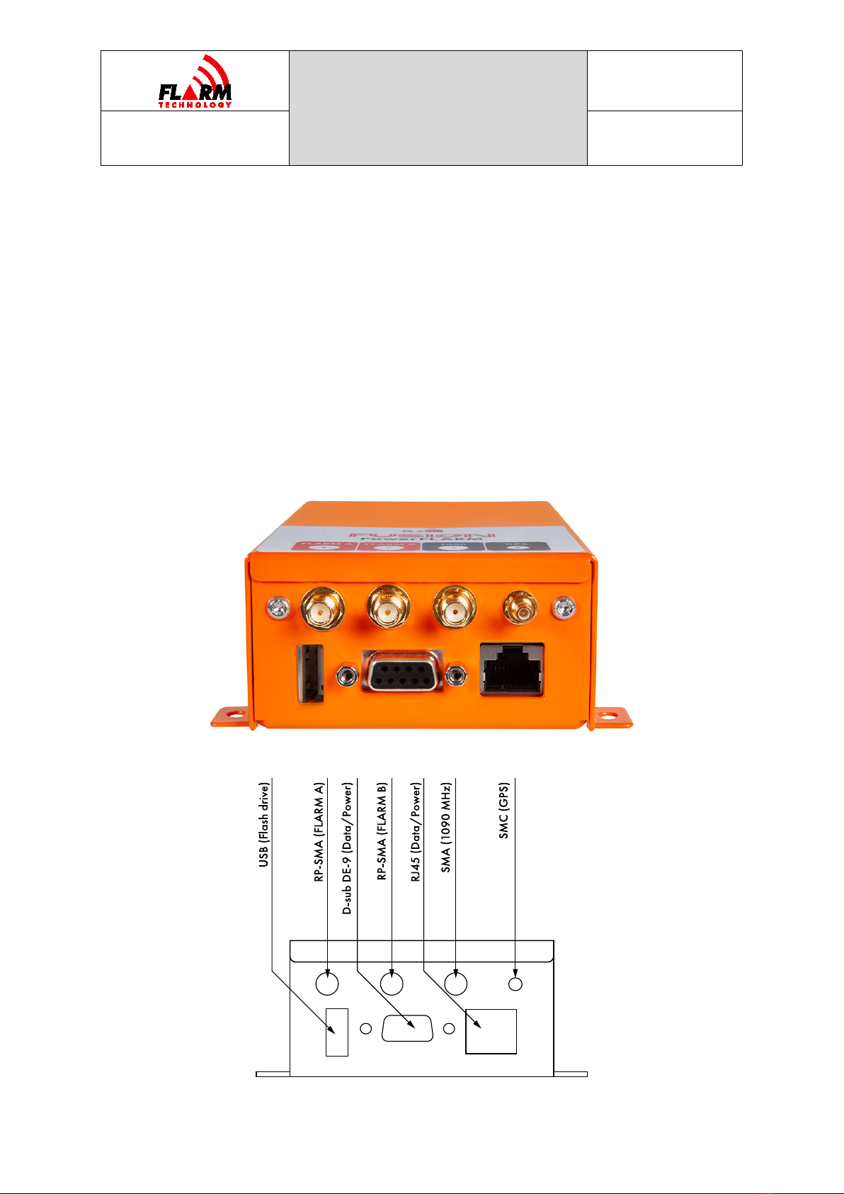
PowerFLARM Fusion has the following connectors:
USB 2.0: Accepts USB flash drive for flight log readout, device update1, and
configuration.
FLARM antennas A and B: When using a single antenna, connect to FLARM
A. The internal FLARM antennas supplied with the device have a RED
marking.
1090 MHz: For receiving SSR transponder and ADS-B 1090ES signals. The
internal antenna supplied with the device has a BLUE marking. This antenna
is optional; however, without it, no traffic will be received on 1090 MHz.
GPS antenna: Must be connected for operation.
RJ45 (Data Port #1) and D-sub DE-9 (Data Port #2): For connecting up to
two independent FLARM Compatible displays and power. Power must only be
supplied on one of the connectors.
For any type of modification, including connected displays, antennas, and other
accessories, see the Installation Manual.
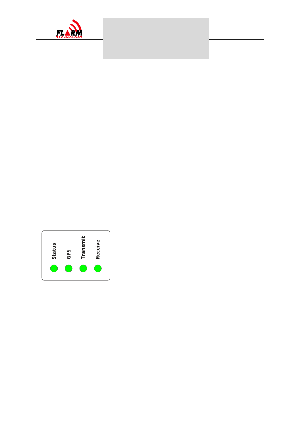
1.3.2 Status LEDs and Startup
PowerFLARM Fusion has 4 LED lights. These lights are normally not visible during
flight. Each LED can be either GREEN, AMBER, RED, or OFF. The different states
have the following meaning, depending on whether the device is in bootloader
mode or if the application has booted, indicated by four amber LEDs:
1The FLARM Hub Firmware cannot be updated using USB.

POWERFLARM
FUSION USER AND
MAINTENANCE
MANUAL
Date: 2020-11-10
Version: 1.0
Page: 12 of 49
FLARM Technology Ltd
Hinterbergstrasse 15
CH-6330 Cham
Document Number:
FTD-078
Status GPS Transmit Receive
BOOTLOADER
Initialization
————
————
————
————
Serial port recovery update
————
————
————
————
Safe update
————
————
————
————
Firmware check error
————
————
————
————
Firmware check successful,
booting application
————
————
————
————
FIRMWARE
Initialization
————
————
————
————
Non-fatal error
————
————
————
————
Fatal error
————
————
————
————
Operation in progress
(obstacle database
installation, IGC readout, etc.)
———————— ———— ————
Nominal state, no GPS fix
————
•—•—•
————
————
Nominal state, 3D GPS fix,
transmitting
————
•—•—•
————
————
Nominal state, 3D GPS fix,
transmitting and receiving at
least one aircraft
————
•
—
•
—
•
————
–––
The LED lights are also visualized in FLARM Hub on the Status page (see Section
3.3).
1.3.3 Factory Reset
PowerFLARM Fusion can be reset to factory defaults if required. The following items
are reverted to factory default:
FLARM configuration
FLARM Hub configuration
Wi-Fi SSID and password
Bluetooth name
The following items are removed/deleted:
IGC flight recordings
FLARM Hub device lock

POWERFLARM
FUSION USER AND
MAINTENANCE
MANUAL
Date: 2020-11-10
Version: 1.0
Page: 13 of 49
FLARM Technology Ltd
Hinterbergstrasse 15
CH-6330 Cham
Document Number:
FTD-078
Bluetooth pairings
Obstacle database
CARP range analyzer data
Diagnostic log files
The firmware versions (PowerFLARM and Hub) do not change.
A factory reset should be applied under the following circumstances:
Installation in another aircraft and/or change of ownership
The Wi-Fi or device lock passwords have been lost
The device can be reset either via FLARM Hub (on the Tools / Support page) or by
using the hardware reset pin. To reset using the pin, push a paperclip or similar
into the hole next to the LED lights (see picture below) with the device OFF, until
the reset pin is pushed in. Hold the pin pushed in while powering on the device.
Hold the pin pushed in for at least 2 seconds and then withdraw the paperclip. The
device will revert to factory configuration during startup.

POWERFLARM
FUSION USER AND
MAINTENANCE
MANUAL
Date: 2020-11-10
Version: 1.0
Page: 14 of 49
FLARM Technology Ltd
Hinterbergstrasse 15
CH-6330 Cham
Document Number:
FTD-078
1.4 Displays
PowerFLARM Fusion must be connected to a FLARM display. Displays originate from
third party manufacturers implementing the FLARM ICD protocol, an extension of
NMEA 0183. To ensure that collision warnings and traffic information work correctly
and that critical status and error conditions are correctly annunciated to the pilots,
Fusion should be connected to at least one FLARM Compatible display. The display
should be installed in the primary field of view of the pilots. In aircraft with tandem
seating, each pilot should have a display in its primary field of view.
Fusion also supports connections to supplementary displays and navigation
systems over Wi-Fi and Bluetooth.
For detailed requirements for FLARM displays, see the Installation Manual.
1.5 Radio Communication and Antennas
The FLARM system uses a radio communication frequency in the SRD860 band
(≈868 MHz) or an ISM band (≈915 MHz) in different parts of the world.
PowerFLARM Fusion will automatically select the applicable frequency based on the
GNSS position.
The following frequencies are used within the specified areas.
Area
Frequency
Africa
868.2 – 868.4 MHz
Australia
917.0 – 926.6 MHz
Europe
868.2 – 868.4 MHz
Israel
916.2 MHz
New Zealand
869.2 MHz
North America
902.2 – 927.8 MHz
South America
917.0 – 926.2 MHz
The antennas should be designed for the frequency band applicable in the
geographic area where the aircraft is being operated. Internal antennas, including
the antennas that are shipped with Fusion, are normally designed for only one of
the frequency bands. The external AV-75 antenna is designed for worldwide use.
Only antennas supplied or approved by FLARM Technology should be used.
Inappropriate antennas, especially antennas without complete insulation, can
damage devices and should not be used.
Note: Fusion will not detect inappropriate antennas, including antennas for the
wrong frequency band.

POWERFLARM
FUSION USER AND
MAINTENANCE
MANUAL
Date: 2020-11-10
Version: 1.0
Page: 15 of 49
FLARM Technology Ltd
Hinterbergstrasse 15
CH-6330 Cham
Document Number:
FTD-078
PowerFLARM Fusion can use two antennas concurrently for better coverage
(antenna diversity). Normally, one antenna is placed on top of the aircraft and one
below. In especially fiberglass gliders, they can also be placed inside the aircraft
fuselage in a way that ensures 360° coverage. Antenna diversity is recommended
for all aircraft and is strongly recommended for aircraft fuselages containing a lot
of metal or carbon fiber.
Note: Communication between FLARM devices employs a proprietary, encrypted,
and copyright protected protocol. The design is patent protected. Any
unlicensed use, copying, distribution, conversion, replication, access,
interception, de-compiling, reverse engineering, or further transmission of
knowledge so acquired relating to the system components or
software/firmware, in whole or in part, is forbidden and will result in legal
enforcement action.
For detailed requirements for antennas and their installation, see the Installation
Manual.
1.6 Additional Documents
The PowerFLARM Fusion Installation Manual (FTD-077) is an integral part of the
maintenance documentation and must be used for maintenance where referenced.
The Installation Manual, together with additional documents for installation,
maintenance, operation, and support can be found under the following link:
https://flarm.com/support/manuals-documents/
For questions, first consult the FAQ:
https://support.flarm.com/hc/en-us
For questions not answered in the FAQ, contact FLARM Technology:
1.7 Document Revisions
This document will occasionally be updated. The latest version can be found under
the link to additional documents above. Always make sure that you are using the
latest document. Updates will be communicated to official FLARM dealers, in the
FLARM blog, and the official FLARM newsletter. Sign up to the newsletter from the
FLARM website to ensure that important communication is not missed:
https://flarm.com/blog/

POWERFLARM
FUSION USER AND
MAINTENANCE
MANUAL
Date: 2020-11-10
Version: 1.0
Page: 16 of 49
FLARM Technology Ltd
Hinterbergstrasse 15
CH-6330 Cham
Document Number:
FTD-078
2Limitations
PowerFLARM Fusion has been designed as a non-essential situation awareness only
device, whose task is solely to support the pilot; it is not always in a position to
provide a reliable warning. In particular, Fusion does not provide any resolution
advisories. Under no circumstances does Fusion facilitate a change in flight tactics
or pilot conduct. Operation of Fusion is solely at the discretion of the PIC. The
system may only be used after completing familiarization training.
A display attached to Fusion can only alert of the presence of other moving aircraft
if the other aircraft is equipped either with a FLARM system, an ADS-B Out 1090ES
device, or an interrogated Mode-S transponder. Fusion does neither interrogate
transponders nor operate as a transponder and is thus not detected by TCAS or
ATC.
FLARM firmware development was conducted in accordance with industry best
practice for industrial electronics products. The use of public access license-free
radio bands in the air is subject to a number of limitations, with some national
differences. The PIC is solely responsible that Fusion is operated in accordance
with applicable regulations.
The use of Fusion is limited to flights in VMC (both VFR and IFR). Fusion may not
be used for navigation.

POWERFLARM
FUSION USER AND
MAINTENANCE
MANUAL
Date: 2020-11-10
Version: 1.0
Page: 17 of 49
FLARM Technology Ltd
Hinterbergstrasse 15
CH-6330 Cham
Document Number:
FTD-078
3FLARM Hub
FLARM Hub is the web app that makes configuring and maintaining FLARM easier
than ever before. It runs directly on the Wi-Fi network of Fusion and can be used
from any smartphone, tablet, or computer.
The following main features are available in FLARM Hub:
Device status
Firmware updates
Interactive configuration
Obstacle database update
IGC file download
Traffic Monitor
Interactive Data Port
Integrated CARP Range Analyzer
Diagnostics
FLARM Hub pages can be printed to paper or PDF for documentation purposes,
using the browser’s print function.
3.1 Connection
Connecting to FLARM Hub is done over Wi-Fi. Fusion presents its own Access Point
(AP) to which a client device can connect. The Wi-Fi is identified via its name
(SSID). When accessing it, the user is prompted to enter the password. SSID and
password can be set in the configuration to restrict access.
Fusion comes with a default SSID and password programmed. Both values are
printed on the black serial number sticker on the device. The sticker also contains
a QR code which can be used to easily connect, provided the SSID and password
have not been changed. For this, simply scan the QR code with the phone’s camera
app. An additional device sticker is included with the device and can preferably be
attached to maintenance documentation to facilitate future connections.
Note: A phone or computer can usually be connected to only one Wi-Fi network
at a time. When connecting to Fusion, you may thus lose Wi-Fi connectivity
to the internet. Phones with a data plan can use the internet while
connected to Fusion.
POWERFLARM
FUSION USER AND
MAINTENANCE
MANUAL
Date: 2020-11-10
Version: 1.0
Page: 18 of 49
FLARM Technology Ltd
Hinterbergstrasse 15
CH-6330 Cham
Document Number:
FTD-078
Next, open a web browser and enter the address http://10.10.10.10/. This will
bring up the Status Page.
FLARM Hub web address (URL):
http://10.10.10.10/
The status page contains another QR code which can be used to connect additional
devices by scanning it (see Section 3.3.5). This QR code always contains the
current settings for Wi-Fi network name and password.
Note: Internet is not available over the Wi-Fi connection. If asked when
connecting, select to use the connection even if no internet is available.
Note: FLARM Hub is not available over TLS/SSL (https).
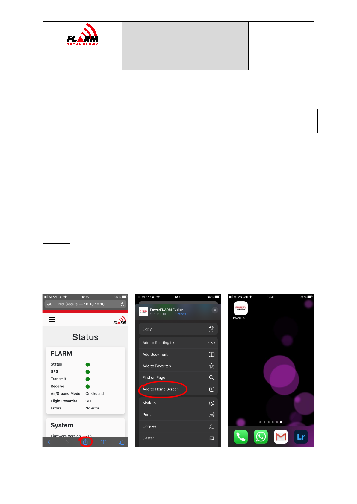
On mobile devices, it is recommended to create a bookmark for FLARM Hub on the
springboard (home screen):
On iOS:
1. Open FLARM Hub in Safari (visit http://10.10.10.10/ and make sure you are
on the Status page)
2. Click the Share button at the bottom of the screen
3. Select “Add to Home Screen”

POWERFLARM
FUSION USER AND
MAINTENANCE
MANUAL
Date: 2020-11-10
Version: 1.0
Page: 19 of 49
FLARM Technology Ltd
Hinterbergstrasse 15
CH-6330 Cham
Document Number:
FTD-078
On Android:
On Android, the procedure depends on the flavor of the OS and the browser. In
general:
1. Open FLARM Hub in e.g. Chrome (visit http://10.10.10.10/ and make sure
you are on the Status page)
2. Click the Menu button to the right of the address bar
3. Select “Add to Home screen”
3.2 General Web Interface Guidance
FLARM Hub has been designed following modern user interface principles and is
easy and intuitive to use. It uses a responsive design and is accessible on both
desktop and mobile. Each page also prints nicely to PDF or paper (great for
documentation purposes).
All dynamic information in FLARM Hub is “live”, i.e. it is updated automatically
when the underlying data changes. Thus, there is normally no need to refresh the
page or to push a button to commit changed settings to the device. If there is a
connection problem, this will be indicated at the top of the page.
The language of the interface can be changed on the Configuration / FLARM Hub
page (see Section 3.4.3.2). Independently of the selected language, all dates are
shown in the international standard format (YYYY-MM-DD).
Note: Some features (e.g. file downloads) do not work on Chrome for iOS
because of how Chrome has been implemented on iOS. Please use Safari
instead.

POWERFLARM
FUSION USER AND
MAINTENANCE
MANUAL
Date: 2020-11-10
Version: 1.0
Page: 20 of 49
FLARM Technology Ltd
Hinterbergstrasse 15
CH-6330 Cham
Document Number:
FTD-078
3.3 Status Page
The Status Page is the first page shown when accessing FLARM Hub and can always
be accessed by clicking on “Status” (first item) in the navigation menu. The Status
Page shows information about FLARM. It also shows connection information to
connect additional mobile devices to FLARM Hub.
The different sections on the Status page are explained below.
3.3.1 FLARM
This section depicts the physical device LEDs and shows their corresponding status
(color). See Section 1.3.2 for details. An LED that is OFF is indicated by a white
LED with a black border. If using a mouse, hover over the Receive LED to see the
number of aircraft being received.
Air/Ground Mode
Indicates if FLARM considers the aircraft to be in flight or on the ground. This
depends on ground speed and the configured aircraft type. When on the ground:
Other manuals for FUSION PowerFLARM
1
Table of contents
Other FLARM Industrial Equipment manuals


