envea M-Sens WR3 User manual

OPERATING INSTRUCTIONS
M-Sens WR3
ONLINE EXTENDED MOISTURE MEASUREMENT FOR SOLIDS
ENVEA Process GmbH - Gutedelstraße 31 – 79418 Schliengen - GERMANY
Tel.: +49 (0) 7635 827248-0 / info.process@envea.global / www.envea.global
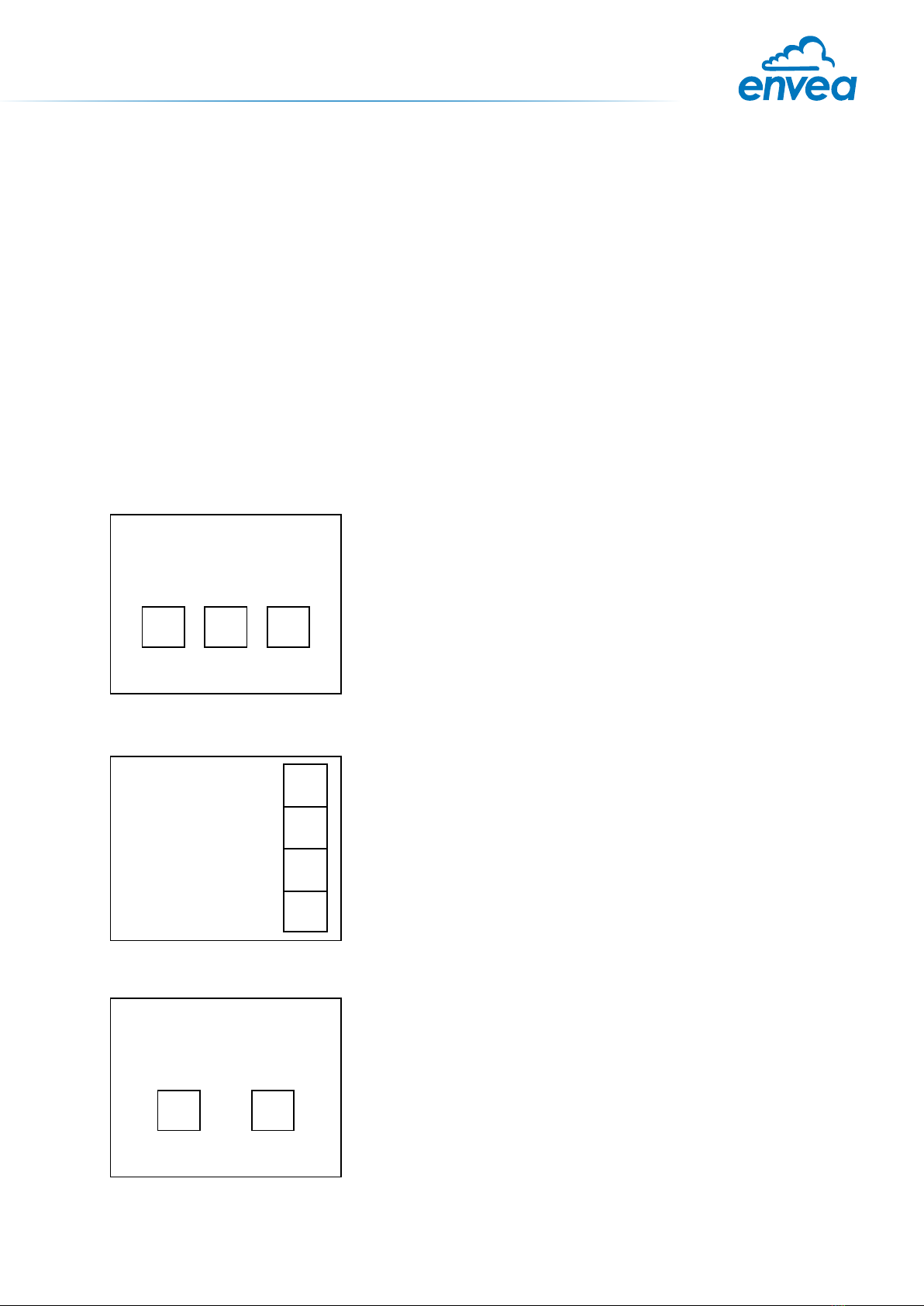
The display is touch-sensitive. Available keys are displayed directly in context. When the measuring
system is rst started, a query is initiated to select the language and sensor.
Initialization screen when the Evaluation unit in the eld housing
started rst time.
Selection of the menu language: Deutsch, English, Français.
If a language has been selected, the sensor to be used must be
selected. To be available:
SolidFlow 2.0, Paddy, PicoFlow, MaxxFlow HTC, DensFlow,
SpeedFlow 2.0, SlideControl 2.0, ProSens, M-Sens 2, M-Sens 3,
M-Sens WR3, AirFlow P.
If any data has been changed, the change will only be taken
into account when you exit the complete menu structure and
answer [Yes] when asked if you wish to save the changes.
Afterwards the start page appears.
If you want to communicate with our sensor using our dedicated software, you need to download the
latest version on our website and install it.
https://www.envea.global/solutions/process-optimization/dahs-software/
It might also be necessary to install drivers, also available on our website.
1st start note
For the 1st use of the sensor, correct sensor type should be selected via the screen or the software.
Software must be installed if needed.
1. SOFTWARE INSTALLATION
2. MSE 300-FH (WITH SCREEN)
Select Language
D E F
E
#
$
8
Sensor
SolidFlow
Save changings?
J N

1st start note
Our dedicated software must be used to connect to the sensor evaluation unit.
Select software language
Right click on „Sprache/Language/
Langue“ and select desired language.
Connect to sensor
Select the correct COM port and
connect to the device using the „read
device“ button.
Select correct sensor
In the menu „System“, under „Sensor“
(8.2.5 or 7.2.5), the correct sensor must
be selected.
After selecting the sensor, check the
box „Overwrite measurement calib.“
and conrm with the button „Device
program“.
For more informations and details, ple-
ase refer to the user manual of the sen-
sor.
3. MSE 300-DR / -DR2 (NO SCREEN)

2
CONTENTS Page
1. System overview . . . . . . . . . . . . . . . . . . . . . . . . . . . . . . . . . . . . . . . . 3
2. Function. . . . . . . . . . . . . . . . . . . . . . . . . . . . . . . . . . . . . . . . . . . . . .5
3. Safety . . . . . . . . . . . . . . . . . . . . . . . . . . . . . . . . . . . . . . . . . . . . . . 6
3.1 Regular use . . . . . . . . . . . . . . . . . . . . . . . . . . . . . . . . . . . . . . . . . 6
3.2 Identication of dangers . . . . . . . . . . . . . . . . . . . . . . . . . . . . . . . . . 6
3.3 Operational safety . . . . . . . . . . . . . . . . . . . . . . . . . . . . . . . . . . . . 6
3.4 Technical progress . . . . . . . . . . . . . . . . . . . . . . . . . . . . . . . . . . . . 6
4. Montage and installation . . . . . . . . . . . . . . . . . . . . . . . . . . . . . . . . . . . . 7
4.1 Delivery parts . . . . . . . . . . . . . . . . . . . . . . . . . . . . . . . . . . . . . . . . 7
4.2 Auxiliary . . . . . . . . . . . . . . . . . . . . . . . . . . . . . . . . . . . . . . . . . . 7
4.3 Mounting of the sensor. . . . . . . . . . . . . . . . . . . . . . . . . . . . . . . . . . .7
4.4 Mounting of the Evaluation unit. . . . . . . . . . . . . . . . . . . . . . . . . . . . . .11
5. Electrical connection . . . . . . . . . . . . . . . . . . . . . . . . . . . . . . . . . . . . . 13
5.1 DIN Rail housing . . . . . . . . . . . . . . . . . . . . . . . . . . . . . . . . . . . . . . 13
5.2 Field housing terminal layout . . . . . . . . . . . . . . . . . . . . . . . . . . . . . . 14
5.3 Terminal layout C-Boxes . . . . . . . . . . . . . . . . . . . . . . . . . . . . . . . . . 15
6. Commissioning . . . . . . . . . . . . . . . . . . . . . . . . . . . . . . . . . . . . . . . . . 16
7. Menu structure of M-Sens WR3 . . . . . . . . . . . . . . . . . . . . . . . . . . . . . . . 17
8. Operator interface . . . . . . . . . . . . . . . . . . . . . . . . . . . . . . . . . . . . . . . 27
8.1 Differences between the DIN Rail and eld housing Evaluation unit . . . . . . . . 27
8.2 Display . . . . . . . . . . . . . . . . . . . . . . . . . . . . . . . . . . . . . . . . . . . 28
8.3 PC interface . . . . . . . . . . . . . . . . . . . . . . . . . . . . . . . . . . . . . . . . 30
9. Wiring example. . . . . . . . . . . . . . . . . . . . . . . . . . . . . . . . . . . . . . . . . 32
10. Maintenance . . . . . . . . . . . . . . . . . . . . . . . . . . . . . . . . . . . . . . . . . . 32
11. Warranty . . . . . . . . . . . . . . . . . . . . . . . . . . . . . . . . . . . . . . . . . . . . 32
12. Troubleshooting . . . . . . . . . . . . . . . . . . . . . . . . . . . . . . . . . . . . . . . . 33
13. Reliability . . . . . . . . . . . . . . . . . . . . . . . . . . . . . . . . . . . . . . . . . . . . 33
14. Technical data . . . . . . . . . . . . . . . . . . . . . . . . . . . . . . . . . . . . . . . . . 34

3
max. 300 m
C1-box
MSE 300-DRSensor
1
2
3
4
1
2
3
4
16 (+ 24 V)
15 (GND)
14 (A)
13 (B)
2 m cable converted
fixed at the sensor
up to 300 m with
correct cablediameter
1. System overview
A complete M-Sens WR3 unit consists of the following components:
•Flange (mounting in screw, hopper)
•1 to 3 sensors with 2 m connecting cable
•Evaluation unit MSE 300
•Optional: C1-box for connecting of sensor and Evaluation unit
The sensor is connected by a shielded, 4-wired cable to the Evaluation unit; the maximal
distance between these devices can be at most 300 m.
Fig. 1: Overview with C1-box and MSE 300-DR
Fig. 2: Overview with C1-box and MSE 300-FH
up to 300 m with
correct cablediameter
max. 300 m
MSE 300-FH
1
2
3
4
S
1
2
3
4
S
1 (+ 24 V)
2 (GND)
3 (A)
4 (B)
Shield
2 m cable converted
fixed at the sensor
Sensor
C1-box
Table of contents
Other envea Industrial Equipment manuals


