Flashcut CNC 401A Installation instructions
™
Computer Numerical Control for Windows
Model 401A
Motor Signal Generator
Hardware Guide
Z
Y
XA
LIMIT
ON
OFF
RXD TXD POWER
© 1998 FlashCut CNC, Inc.
1263 El Camino Real, Suite W, Menlo Park, CA 94025
Phone (650) 853-1444 •Fax (650) 853-1405 •www.flashcutcnc.com


Table of Contents
GETTING STARTED..........................................................................................................................................1
ABOUT THIS MANUAL..........................................................................................................................................1
SYSTEM SAFETY..................................................................................................................................................2
HARDWARE GUIDE..........................................................................................................................................3
OVERVIEW OF THE MOTOR SIGNAL GENERATOR...................................................................................................3
FRONT PANEL .....................................................................................................................................................3
REAR PANEL .......................................................................................................................................................3
TURNING OFF THE CONTROLLER ..........................................................................................................................6


FlashCut CNCFlashCut CNC SectionSection 11 Getting StartedGetting Started 11
1. Getting Started
About this Manual
FlashCut CNC is a unique application involving both hardware and software, so
you’ll need some instruction to get started.
Since automated machining is potentially dangerous, please take
the time to completely read through this manual and the Software
User’s Guide to understand the operation of the electronics,
software and machine before cutting a part.
Section

FlashCut CNCFlashCut CNC SectionSection 11 Getting StartedGetting Started22
System Safety
If you do not understand and agree with all of the above safety
guidelines, do not use this product.
1. Never let the machine run unattended.
2. Any person near a running machine tool must wear safety goggles.
3. Allow only trained people to operate the machine. Anyone
operating this machine must have:
•Knowledge of machine tool operation.
•Knowledge of personal computer operation.
•Knowledge of microsoft windows.
•Good common sense.
4. Place safety guards around the machine to prevent injury from
flying objects. FlashCut CNC highly recommends building a
plexiglass safety shield around the entire tool envelope.
5. A computer controlled machine tool is potentially dangerous.
Unexpected machine movement can occur at any time. Never
place any part of your body within the tool envelope while the
machine is online.
6. Be aware and on alert for computer crashes at all times.
7. Always keep the tool envelope tidy and free of any loose objects.
8. FlashCut CNC is not responsible for the safe installation and use
of this product. You and only you are responsible for the safety of
yourself and others during the operation of your CNC machine
tool. FlashCut CNC supplies this product but has no control over
how it is installed or used. Always be careful!
When running any machining operation, safety is of utmost
importance. For proper and safe use of the FlashCut CNC program
and your CNC machine, the following safety guidelines must be
followed:

FlashCut CNCFlashCut CNC SectionSection 22 Hardware GuideHardware Guide 33
2. Hardware Guide
Overview of The Motor Signal Generator
The Motor Signal Generator provides a flexible interface that controls up to 4
stepper motor drivers, 8 output lines and 8 input lines.
Front Panel
The front panel of the signal generator has the power on/off switch and 8 LED’s
which have the following functions:
Z
Y
X
A
LIMIT
ON
OFF
RXD TXD POWER
Limit - Turns red when any limit/input switch is open (using normally
closed switches).
X, Y, Z, Α- Turns green when the respective motor is stepping. Note that
the polarity of these lights will be reversed if the Park Signal is set to Low
in the Motor Signals setup screen.
RXD - Turns yellow when receiving data from the host PC.
TXD - Turns yellow when transmitting data to the host PC.
Power - Turns green when the power switch is turned on.
On/Off Switch - Turns the unit on and off. If there is ever a
communications error while running FlashCut CNC, turn the switch off and
on to reset the internal microprocessor.
Rear Panel
The rear panel has connectors for input and output signals as described below.
Model No. 401A
S.N.__________
WPI
Menlo Park, CA
POWER
RS-232
INPUT
OUTPUT
MOTOR SIGNALS
FUSE
Section

FlashCut CNCFlashCut CNC SectionSection 22 Hardware GuideHardware Guide44
DC IN - Receptacle for the power supply. The unit is shipped with a 9V
DC, 800-1000mA wall transformer power supply.
Fuse - Cartridge for the fuse. If the fuse blows, replace it with a 3AG,
1.5A slow-blow fuse.
RS-232 - Serial port connector for communication with the host PC ( 9 pin
female). Most PC’s have 9 pin male or 25 pin male. Use either a 9 Pin
Male - 9 Pin Female or a 9 Pin Male - 25 Pin Female cable depending on
the serial port on your PC.
INPUT - The connector for up to 8 input lines. The most common use of
the input lines is for limit or safety switches. These lines are all TTL level
inputs. When a switch is open, its input signal is high (+5V). When the
switch is closed, its input signal is grounded low (0V).
The 401A is wired for normally closed (NC) switches. Each line that is not
connected to a switch must be wired directly to its ground. When any of
the input lines are open the red limit light will illuminate and a signal will be
sent to the host PC to indicate which input line(s) went high. You can use
normally open (NO) switches, however the red limit light will not function
properly. Note that all 8 input lines must be normally open, or all 8 input
lines must be normally closed. If you are not using the input lines, the limit
light will always be illuminated.
If you are using normally closed switches, make sure the Signal Generator
Model 401A option is chosen in the System Options setup screen. If you
are using normally open switches, make sure the Signal Generator Model
401 option is chosen in the System Options setup screen. All input lines
must be properly defined in the Input Lines Setup screen .
BE VERY CAREFUL WHEN DOING ANY WIRING. IMPROPER
WIRING WILL DAMAGE THE MOTOR SIGNAL GENERATOR.
The receptacle that plugs into this connector is a Molex-Waldom Mini-Fit
Jr. Series 16 pin receptacle (part number 39-01-2160), with female pins
(part number 39-00-0039). The input lines as seen from the back of the
box are arranged as follows:
GGGG
GGGG
8642
7 5 3 1
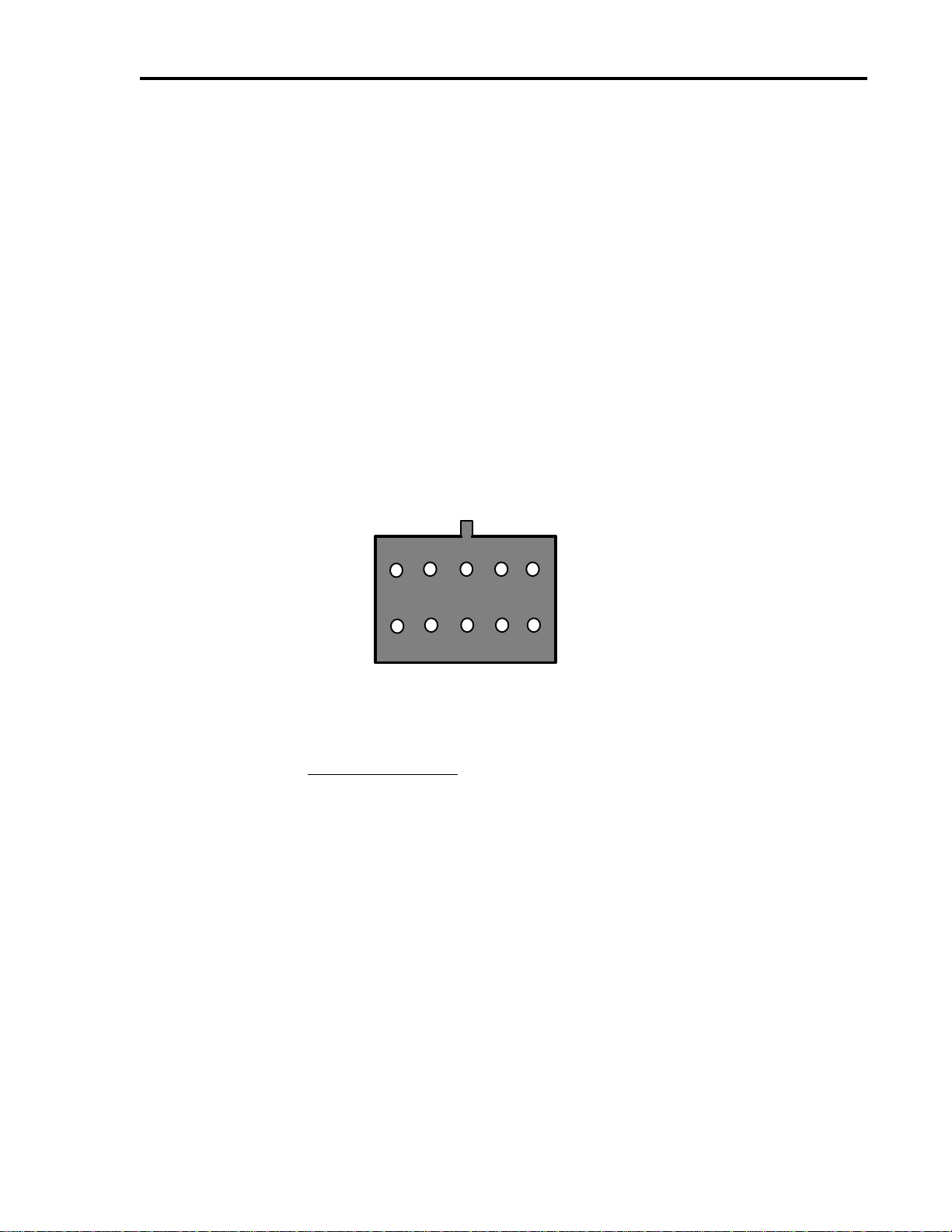
OUTPUT - The connector for up to 8 output lines. These lines are all
optically isolated, TTL level outputs. Low is 0V and high is +5V.
FlashCut CNCFlashCut CNC SectionSection 22 Hardware GuideHardware Guide 55
Two input pins are provided for optical ground and optical +5V. You
must connect these pins to ground and +5V from an external power
supply for the output signals to operate. Note that these pins are
internally connected to the optical ground and optical +5V pins on the
motor signal connector. Therefore, if you are connecting a power
supply to the optical ground and optical +5V pins on the motor signal
connector, do not connect an external power supply here.
BE VERY CAREFUL WHEN DOING ANY WIRING. IMPROPER
WIRING WILL DAMAGE THE MOTOR SIGNAL GENERATOR.
The output lines are all initialized to low (0V) when you turn on the Motor
Signal Generator.
The receptacle that plugs into this connector is a Molex-Waldom Mini-Fit
Jr. Series 10 pin receptacle (part number 39-01-2100), with female pins
(part number 39-00-0039). The output lines as seen from the back of the
box are arranged as follows:
GND
+5V
8
6
42
7531
OPT
OPT
MOTOR SIGNALS - The DB-25 male connector for all signals going out
to the stepper motor driver(s). If you are using one of the FlashCut CNC
stepper motor drivers, connect this to the DB-25 female connector on the
stepper motor driver using a DB25 M-F interface cable.
The cable used must be a DB-25 Interface Cable with all 25-pins
wired straight through.
The motor signal lines are all optically isolated, TTL level outputs.
Two input pins are provided for optical ground and optical +5V. You
must connect these pins to ground and +5V from an external power
supply or the internal power supply for the output signals to operate.
Note that these pins are internally connected to the optical ground
and optical +5V pins on the 10-pin output connector. Therefore, if
you are connecting an external power supply to the optical ground
and optical +5V pins on the 10-pin output connector, do not connect
an external power supply here.
FlashCut CNCFlashCut CNC SectionSection 22 Hardware GuideHardware Guide66
BE VERY CAREFUL WHEN DOING ANY WIRING. IMPROPER
WIRING WILL DAMAGE THE MOTOR SIGNAL GENERATOR.
Two pins are directly connected to ground and +5V from the internal
power supply. These are provided for convenience as a source for the
optical ground and optical +5V if there is no external power source
available. Using the internal supply to power the optical isolators will
negate most of the isolation provided by the optical isolators. To use the
internal supply, directly connect DB-25 pin 24 to 25 and pin 22 to 23.
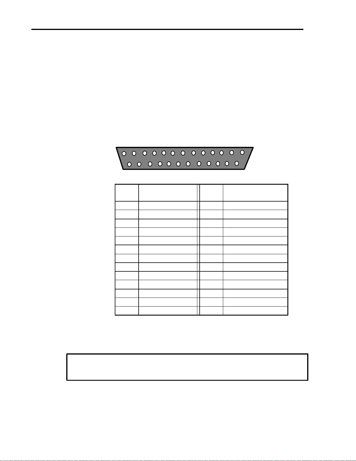
The motor signal lines as seen from the back of the box are arranged as
follows:
113
14 25
DB25
Pin Signal DB25
Pin Signal
1NC 14 ENABLE ALL
2NC 15 θPARK
3NC 16 Z PARK
4NC 17 Y PARK
5NC 18 X PARK
6NC 19 θDIRECTION
7NC 20 Z DIRECTION
8NC 21 Y DIRECTION
9X DIRECTION 22 Internal VCC +5V
10 θSTEP 23 OPT VCC (INPUT)
11 Z STEP 24 Internal GND
12 Y STEP 25 OPT GND (INPUT)
13 X STEP
Turning off the Controller
Always turn off the motor signal generator when it is not in
use.
Other manuals for 401A
1
Table of contents


