BEAMEX MC6-Ex User manual

USER MANUAL FOR BEAMEX MC6-EX,INTRINSICALLY SAFE
ADVANCED FIELD CALIBRATOR AND COMMUNICATOR
Applies to firmware version 3.10
Dear user,
We have made every effort to ensure the accuracy of the contents of this man-
ual. Should any errors be detected, we would greatly appreciate to receive sug-
gestions to improve the quality of the contents of this manual.
For more detailed technical data about Beamex MC6-Ex, Intrinsically Safe Ad-
vanced Field Calibrator and Communicator, please contact the manufacturer.
8861000 / MC6-ExuEng / Version 3.10
© Beamex 2018
BEAMEX OY AB
Ristisuonraitti 10
FIN-68600 Pietarsaari
FINLAND
Tel +358 - 10 –5505000
Fax +358 - 10 –5505404
E-mail: [email protected]m
service@beamex.com
Internet: https://www.beamex.com


MC6-Ex User Manual - Contents i
CONTENTS
Part 1, Introduction
General 2
About This Manual..................................................................2
Where Am I?....................................................................2
Typographical Conventions .............................................3
Unpacking and Inspection ......................................................3
About MC6-Ex 4
Starting MC6-Ex.....................................................................4
Firmware ................................................................................5
Hardware................................................................................7
General............................................................................7
Connectors on Top of MC6-Ex.........................................8
Connectors on the Right Side of MC6-Ex ........................8
Internal Barometric Pressure Module...............................9
Memory ...........................................................................9
Display.............................................................................9
Front Panel LED..............................................................9
The support ...................................................................10
About the Charger and the Charging Procedure............10
Batteries........................................................................10
Removing/Replacing the Battery Back...........................11
Checking the Charge Level of the Battery Back.............11
PC Communication / Calibration Software............................12
USB Communication Driver...........................................12
MC6-Ex Related Tools Available for PC ........................12
Options 13
Software Options ................................................................. 13
Hardware Modules/Options and Accessories....................... 14
Related Products ................................................................. 14
Part 2, Active Terminals and Connections
General 16
Measurements 17
Pressure Measurement........................................................ 17
Connecting and Disconnecting External Pressure
Modules ........................................................................ 17
Zeroing a Pressure Module........................................... 17
Current Measurement.......................................................... 18
Voltage Measurement.......................................................... 18
Temperature Measurement (Thermocouple)........................ 19
Temperature Measurement (RTD)....................................... 19
Resistance Measurement .................................................... 20
Frequency Measurement..................................................... 20
Pulse Counting..................................................................... 21
Switch Sensing .................................................................... 21
Generations/Simulations 22
Changing the Generated/Simulated Value........................... 22
Using the Soft Numeric Keypad .................................... 22
Spinning........................................................................ 23
Current Generation (Source or Sink).................................... 24
Voltage Generation.............................................................. 24
Thermocouple Simulation .................................................... 25
RTD Sensor Simulation........................................................ 25
Resistance Simulation.......................................................... 26
Frequency Generation ......................................................... 26
Pulse Generation................................................................. 27
Thermocouple Connections 28

ii MC6-Ex User Manual - Contents
Part 3, Meter
About Meter 30
Part 4, Calibrator
About Calibrator 32
Tools 33
General................................................................................33
Part 5, Documenting Calibrator
General 36
Calibration Software............................................................. 36
Calibrating Instruments 37
Generating/Simulating the Input Value..........................37
Instrument List .....................................................................38
Instruments...................................................................38
Instrument List Window Menu .......................................39
Plant Structure Levels................................................... 39
Work Order View Mode................................................. 40
Instrument Overview Window............................................... 41
Calibrating an Instrument Using MC6-Ex ............................. 41
Changing the Pressure Module During Calibration........43
About Fieldbus and HART Device Specifics..................44
Group Calibration 45
Collecting Instruments/Functions for Group Calibration........45
Editing a Group..............................................................46
Calibrating a Group ..............................................................46
Group Settings...............................................................47
Performing the Calibration.............................................47
Calibration Results 48
Deleting Calibration Results .................................................48
Digital Communication and MC6-Ex's Instrument Data 49
Getting and Editing Mapped Data.........................................49
Preparations..................................................................49
Getting Default Mappings ..............................................50
Customizing the Mappings.............................................50
Part 6, Data Logger
General 54
Doing a Data Log 55
Configuring...........................................................................55
Saving and Opening Configurations ..............................55
Starting the Data Log............................................................56
Viewing and Saving or Deleting the Results .........................57
Viewing Saved Data Log Results..........................................57
Transferring Data Log Results to a Personal
Computer .............................................................................58

MC6-Ex User Manual - Contents iii
Part 7, Communicator
General 60
Warnings..............................................................................61
Connections 62
Selecting the Instrument 63
List of Found Devices...........................................................63
About Instrument Parameters 64
Instrument Parameters in General........................................64
Calibrating or Data Logging HART instruments ....................65
Calibrating or Data Logging Fieldbus Instruments ................65
Editing Parameters...............................................................66
Trimming a Fieldbus instrument............................................67
Trimming a HART instrument ...............................................68
HART Device Description Specifics 69
General ................................................................................69
Basic View.....................................................................70
Managing Smart Transmitter Configurations 71
General ................................................................................71
Tools in MC6-Ex...................................................................71
Saving Configurations....................................................71
Viewing/Managing Configurations..................................72
Beamex MC6 Fieldbus Configuration Viewer........................72
Uploading Configurations...............................................72
Linking Configurations to CMX.......................................72
Part 8, Settings
Settings 74
Optional Security Tool 75
General................................................................................ 75
Applied Restrictions ...................................................... 75
Supervisor Window....................................................... 76
Part 9, Additional Information
Additional Information 78
User Defined Pressure Units................................................ 79
User Defined PRT / RTD Sensors........................................ 80
General......................................................................... 80
Callendar van Dusen Formula for PRTs........................ 81
ITS-90 PRT Sensor....................................................... 81
Factor............................................................................ 83
Check Sensor Conversion............................................. 83
User Defined Transfer Functions.......................................... 84
User Defined Steps / Calibration Points ............................... 85
Controller Communication.................................................... 86
What Can be Done With Controller
Communication............................................................. 86
Configuring Controller Communication.......................... 87
Changing Controller During Calibration......................... 87

iv MC6-Ex User Manual - Contents
Appendix
Safety 90
Approvals............................................................................. 90
Symbols Used...................................................................... 91
Safety Precautions and Warnings........................................ 91
Operating Conditions..................................................... 91
General Warnings......................................................... 92
Warnings Concerning Electrical Measurement
and Generation .............................................................92
Warnings Concerning the Ni-MH Battery Pack..............93
General Warnings Concerning Pressure
Measurement................................................................94
Warnings Concerning High Pressure ............................ 95
Safety Information Related to Intrinsical Safety.................... 96
Input Parameters, Simple Connections .........................96
Output Parameters, Simple Connections.......................96
Combined Connections................................................. 96
Ex Approvals.................................................................97
Special Conditions for Safe Use.................................... 97
Disposal of Waste Electrical and Electronic Equipment 98
Beamex and WEEE .............................................................98
Disposal of Battery Pack ...............................................98
Service 99
Sending MC6-Ex for Service ................................................99
Updating MC6-Ex Firmware and Battery Pack
Firmware ..............................................................................99
MC6-Ex's Firmware Update...........................................99
Battery Pack's Firmware Update....................................99
Resetting MC6-Ex ..............................................................100
The Battery Charger...........................................................100
Recalibrating MC6-Ex.........................................................100
Cleaning MC6-Ex ...............................................................100
Statements 101
Disclaimer...........................................................................101
CE......................................................................................101
Intellectual Property Rights.................................................102
Copyright.....................................................................102
Trademarks .................................................................102
Third-party Licenses in MC6-Ex's Battery Pack's
Software......................................................................103
Index 105

MC6-Ex User Manual - Feedback v
FEEDBACK
We want to improve our products and services constantly. Therefore we’d like
to know Your opinion of the product You use. Please spend a moment of Your
valuable time in filling this form. All respondents will receive a surprise gift in
return.
Certain questions can be answered immediately after receiving the product.
Others require some use of the product before You are able to answer them.
The best way to fill the form is to answer the items as it applies, and send the
form to us when all items are answered. There are however no definite re-
strictions; fill in the form when you feel like it (all items need not be answered).
Then send it to Beamex using one of the possibilities listed to the right.
Mail: Beamex Oy Ab
Quality Feedback
Ristisuonraitti 10
FIN-68600 Pietarsaari
FINLAND
Fax: +358 - 10 - 5505404
Only the next page needs to be
faxed to us.
Internet: https://www.beamex.com
A similar form is available as a web page
E-mail: [email protected]
Refer to the numbered items on the next
page in Your e-mail message.
vi MC6-Ex User Manual - Feedback
1. Name of the product you give feedback of:
_____________
2. Serial number and software version number
_____________ / _____________ (if applicable)
3. Any comments when receiving the product. Did the package con-
tain all required items and was it as expected?
____________________________________________
____________________________________________
____________________________________________
4. For how long have you been using the product?
_____________
5. How helpful was the manual in using the product?
(Tick a box in the percentage scale below)
6. How well did the product suit your needs?
7. How satisfied are you with the product?
8. Did anything in the product exceed your expectations? In that
case, what was it?
____________________________________________
____________________________________________
____________________________________________
9. Did anything in the product disappoint you? In that case, please
specify.
____________________________________________
____________________________________________
____________________________________________
10. Any ideas You want to propose to Beamex so that we can im-
prove our products, operations and/or services.
____________________________________________
____________________________________________
____________________________________________
Title & Name: ______________________________________
Address: ______________________________________
__________________________________
__________________________________
Please contact me concerning the Feedback I have given.
I want to receive more information on Beamex products.

Things discussed in this part:
About this manual
Briefly about MC6-Ex's hardware and firmware
Available software and hardware options
Part 1
INTRODUCTION

2 MC6-Ex User Manual –Part 1, Introduction
GENERAL
Thank you for buying Beamex MC6-Ex, Intrinsically Safe Advanced Field Cali-
brator and Communicator. Because of its versatile features, it really is "more
than a calibrator".
MC6-Ex is one device with five different operational modes: Meter, Calibrator,
Documenting Calibrator, Data Logger and Fieldbus Communicator.
Attention!
Before taking MC6-Ex into use, please read the warnings
available in Appendix.
ABOUT THIS MANUAL
MC6-Ex User Manual is divided into several parts as follows:
Part 1, Introduction discusses general matters.
Part 2, Active Terminals and Connections. Whatever you measure,
generate or simulate, here's how to make the necessary connections.
Part 3, Meter introduces the metering tool, which is handy for making
quick measurements. One measurement at a time.
Part 4, Calibrator. A more versatile tool which allows you to meas-
ure/generate/simulate two things simultaneously etc.
Part 5, Documenting Calibrator concentrates on instrument calibration
using the full featured documenting calibrator.
Part 6, Data Logger. Collecting and reviewing
data and transferring logged data to a PC.
Part 7, Communicator. Invoking digital com-
munication with modern instruments.
Part 8, Settings. How to customize MC6-Ex
and what the About window contains.
Part 9, Additional Information. About ad-
vanced tools for, e.g. adding custom pressure
units, connecting external devices etc.
WHERE AM I?
The header of each spread in MC6-Ex User Manual informs you of where you
are: The even page shows the part you are in and the odd page shows the
main topic you are currently viewing.
Example of even page header:
2 MC6-Ex User Manual –Part 1, Introduction
Example of odd page header:
General - About This Manual 3

General - Unpacking and Inspection 3
TYPOGRAPHICAL CONVENTIONS
The following typographical conventions apply to MC6-Ex User Manual:
Bold text is used in following situations:
References to User Manual topics and parts,
MC6-Ex keywords, i.e. terms shown in the User Interface and
other keywords, e.g. the names of fieldbus parameters.
Notes are shown in Narrow text with a border above and to the
left of the note text. Notes typically inform you of something
useful concerning the current topic.
Warnings are shown in Narrow and Bold. They also have a
shaded background and are surrounded by a border line.
Whenever you see a warning, read it carefully and take it
seriously. By not observing warnings, you may - at worst -
damage the calibrator and/or even risk your life.
UNPACKING AND INSPECTION
At the factory each new MC6-Ex passes a careful inspection. It should be free
of scrapes and scratches and in proper operation order upon receipt. The re-
ceiver should, however, inspect the unit for any damage that may have oc-
curred during transit. If there are signs of obvious mechanical damage, package
contents are incomplete, or MC6-Ex does not operate according to specifica-
tions, contact the purchasing sales office as soon as possible.
If you have to return the instrument to the factory for any reason, use the origi-
nal packing whenever possible. Include a detailed description of the reason for
the return. Read also chapter Sending MC6-Ex for Service in Appendix.
For a description of available options, see Options on page 13.
Standard accessories:
Accredited calibration certificate,
this User Manual and a leaflet entitled
"MC6-Ex Safety Information",
Warranty Card,
pre-installed internal rechargeable Nickel Met-
al Hydride (NiMH) battery pack,
test leads,
clips as follows:
a pair of Grabber clips and
two pairs of Alligator clips,
battery charger/eliminator and
USB cable.

4 MC6-Ex User Manual –Part 1, Introduction
ABOUT MC6-EX
STARTING MC6-EX
Start MC6-Ex by pressing the Power button for a few seconds. The startup pro-
cedure ends in Home View (see picture on the right). From MC6-Ex's Home
View you may advance to any of the available main functions. This manual con-
tains detailed information of main functions as follows:
Meter in Part 3,
Calibrator in Part 4,
Documenting Calibrator in Part 5,
Data Logger in Part 6,
Communicator in Part 7 and
Settings in Part 8.
With the Home button (see picture on the right) you can always return to Home
View from wherever you are.
When MC6-Ex is already running, pressing the Power button briefly opens a
dialog with the following options:
Power Off to shut down MC6-Ex in Backup Mode, i.e. minimum power
consumption and full startup procedure.
Standby to set MC6-Ex in Standby Mode allowing faster startup when
the Power button is pressed again.
Backlight Off to temporarily set the backlight off.
The buttons available in the dialog (top to bottom):
Power Management to define Backlight Brightness and other power
management related settings. More in Part 8, Settings.
MC6-Ex Safety Information. Detailed information in Appendix.
Power button (left) and Home button (right).
Home View
Note.
Certain main functions are options. They may not be available
in your MC6-Ex. More of this in chapter Options on page 13.
About MC6-Ex - Firmware 5
FIRMWARE
You can interact with MC6-Ex by tapping on available buttons/controls dis-
played on the touch screen. Optionally: use the hardware arrow keys to move
between the available buttons/controls. The first time you push a hardware ar-
row key the Hardware Focus Indicator is displayed (a blue border around the
active button/control). When using the hardware arrow keys, use the hardware
Enter key to select ("tap") a button/control.
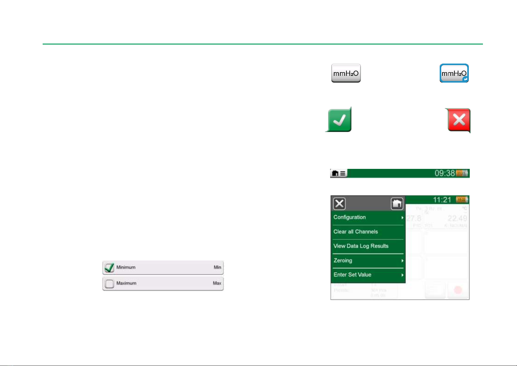
Buttons often open a pop-up window for entering data, e.g. a unit button with
the text "mmH2O" opens a pop-up window of available units. Certain buttons do
have special functionality, like "Accept" and "Close" buttons. They close a pop-
up window and either accept or reject the changes. There are other buttons,
e.g. for going to the next/previous page pages, scrolling through a wide table of
data, removing a number in a numeric field (backspace), clearing a numeric
field, etc. Most of them are familiar since they look similar as in personal com-
puter software.
One important button is the Menu button which is available in the upper left
corner of almost any window. Tap on it to open a context-sensitive menu with,
among other things, a software version of the Home button presented on previ-
ous page.
Check Boxes are special buttons that are either "checked" or "unchecked".
See picture below. Again, the functionality is familiar from personal computers.
Check Boxes, both a checked
and an unchecked one.
Button without and with a Hardware Focus Indicator.
Accept button. Close button.
Menu button to the left.
Example of an opened menu.
6 MC6-Ex User Manual –Part 1, Introduction
MC6-Ex also has some "flat" buttons. They are used in, e.g lists. The color of
the flat buttons may vary depending on the context.
The following editable fields are available:
Text Fields,
Numeric Fields, in certain cases including Spinning and
Date/Time Fields.
The letters/numbers on all editable fields are blue to indicate that they are ed-
itable. Black texts are descriptive user interface texts that are not editable. An
example of a Text Field and the Text Edit Window is at the bottom right of this
page.
Use of Numeric Fields and Spinning is described in Part 2, Active Terminals
and Connections and Part 5, Documenting Calibrator.
Date Fields are actually special cases of Numeric Fields. Entering the date is
just like entering any numeric value.
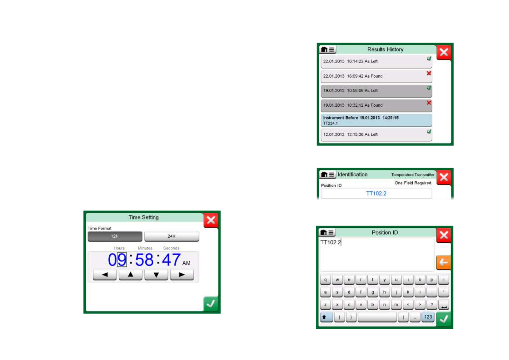
Setting MC6-Ex's time is a special case of the Spinning functionality. See pic-
ture below. The "Left" and "Right" arrow buttons move the highlight to another
digit. The "Up" and "Down" arrow buttons change the value of the highlighted
digit.
Time Setting window
Example of a list with flat buttons.
Text Field
Text Edit window

About MC6-Ex - Hardware 7
HARDWARE
GENERAL
MC6-Ex, front and right side shown.
Legend:
1. Thermocouple connector (TC1) with release
buttons. For cables and standard TC plugs.
2. Thermocouple connector (TC2). For TC plugs
with flat contacts.
3. RTD and Resistor connector (R1). An R2
connector is on the top of MC6-Ex. More of R2
connector on next page.
4. Voltage, Current and Frequency output
(OUT).
5. Voltage, Frequency and Switch input (IN and
Com).
6. Current Measurement (mA), Supply voltage
and Smart instrument (HART®and Fieldbus)
connection.
7. Home button. Press this button to return to
Home View.
8. Arrow buttons. First press displays the Hard-
ware Focus Indicator. Further presses move
the indicator on the touch screen.
9. Enter button for selecting the item surrounded
with the Hardware Focus Indicator.
10. Connectors on the right side of MC6-Ex.
More in chapter Connectors on the Right
Side of MC6-Ex on page 8.
11. Power button. More in chapter Starting MC6-
Ex on page 4.
12. Light Emitting Diode (LED). More in chapter
About the Charger and the Charging Pro-
cedure on page 10 and Front Panel LED on
page 9.

8 MC6-Ex User Manual –Part 1, Introduction
CONNECTORS ON TOP OF MC6-EX
Items from left to right:
R2. A possibility to connect an external RTD sensor to MC6-Ex. See al-
so Hardware Modules/Options and Accessories on page 14.
P1 and P2. Internal Gauge Pressure Module connectors. These are op-
tional. You may have zero to two Internal Gauge Pressure Modules on
your MC6-Ex. See also note to the right and chapter Internal Baromet-
ric Pressure Module on page 9.
PX. A possibility to connect Beamex External Pressure Modules to
MC6-Ex. See also adjacent warning.
MC6-Ex, top view.
Warnings!
Use only EXT-IS or EXT-s-IS pressure modules in Ex area.
If you have EXT-modules that are not intrinsically safe,
they may be used in safe area only.
After cleaning the overpressure blow holes of pressure
modules, tighten the pressure module shield (green high-
light in picture above) using max 0.4 Nm torque.
If you use other pressure hoses than the one delivered by
Beamex, remove the connector meant for Beamex's pressure
hoses and replace them with your own connectors. The thread
available in a Pressure Module's body is 1/8" BSP.
R2 connector's pin order:
Outside view of the female
connector in MC6-Ex.
1 Excitation current +
2 Sense +
4 Sense -
5 Excitation current -
Note.
Leave pins 3, 6 and 7 unconnected in the male connector
meant for MC6-Ex's R2 connector.
CONNECTORS ON THE RIGHT SIDE OF MC6-EX
The Connectors on the right side of MC6-Ex are:
USB-A connector for connecting USB devices to MC6-Ex. For exam-
ples, see External Controllers in chapter Options on page 13 and Firm-
ware Update in section Appendix.
USB-B connector for communicating with a Personal Computer. For de-
tails concerning communication, see PC Communication / Calibration
Software on page 12.
Connectors on the right side of MC6-Ex
WARNING!
USE THE USB CONNECTORS IN SAFE AREA ONLY.
Display
R2 P1 P2 PX

About MC6-Ex - Hardware 9
INTERNAL BAROMETRIC PRESSURE MODULE
The optional Internal Barometric Pressure Module is located inside MC6-Ex. It
has a venting hole on the back side of MC6-Ex. To ensure valid barometric
pressure measurements, do not plug the venting hole.
MEMORY
MC6-Ex maintains data very much like personal computers. Data is saved on a
solid state memory that does not need any power to maintain its state. Solid
state memory is shock-proof so the data is not lost when the calibrator is trans-
ported. Also, you can safely save a large amount of instruments, calibration
results and data log results.
Available memory can be used for anything that requires it (e.g. instrument da-
ta, calibration results etc.).
DISPLAY
MC6-Ex has a backlit 640 × 480 pixel 5.7" TFT touch screen display. Use the
touch screen with your fingers, gloves on or off. Optionally, use a stylus meant
for touch screen use.
See also brightness settings in Part 8, Settings.
FRONT PANEL LED
MC6-Ex's Light Emitting Diode (LED) indicates battery/charging status as fol-
lows:
When charger is connected and charging is in progress, the LED flashes
approximately once every second.
The LED is constantly lit when the charging of the batteries is ready
(with charger still connected).
When battery charge level is low, the LED is lit for a second in approx.
10 second intervals.
Venting hole of the Internal Barometric Module.
Note.
The Internal Barometric Pressure Module is not located in the
space reserved for Internal Gauge Modules, so you may have
both a barometric module and up to two gauge modules in your
MC6-Ex.
Warning!
Using sharp tools such as a screwdriver on the touch
screen may damage it. More warnings in Appendix.
Note.
When batteries have capacity enough to continue working with
MC6-Ex, the LED is not lit during normal operation.
10 MC6-Ex User Manual –Part 1, Introduction
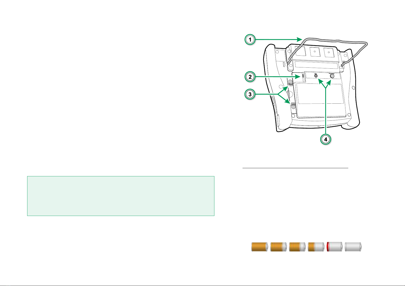
THE SUPPORT
The support (#1in the adjacent picture) can be lifted up to support MC6-Ex
when it is placed on a table. At the same time the support is out of Battery
Pack's way, if you need to change the Battery Pack. If you rotate the support
further up, it can be used to hang MC6-Ex to e.g. a pipeline leaving your hands
free during instrument calibration.
ABOUT THE CHARGER AND THE CHARGING PROCEDURE
The charger connector is marked #2in the adjacent picture. MC6-Ex may be
used while the batteries are charged. Charging time from empty to full batteries
is approximately 6 to 8 hours. Charge within the following temperature range: 0
°C to +40 °C (+32 °F to +104°F). During charging, the battery pack's led (#4in
the adjacent picture) indicates the charge status as described in the table to the
right.
When charging the batteries, a battery symbol and a plug symbol alternate on
the status bar. When charging is ready, only the plug symbol is shown. If MC6-
Ex is shut off and the charger is connected, a battery symbol appears. After a
while, an estimate of the remaining charge time appears below the battery
symbol.
Warning!
THE CHARGER MAY BE USED IN SAFE AREA ONLY.
USE THE CHARGER PROVIDED WITH THE CALIBRATOR ONLY. FURTHER WARNINGS
PRESENTED IN CHAPTERS WARNINGS CONCERNING THE NiMH BATTERY PACK AND
CHARGING THE NiMH BATTERY PACK,
BOTH IN APPENDIX.
BATTERIES
MC6-Ex has a removable, rechargeable Nickel Metal Hydride (NiMH) battery
pack type RB-796-Ex. A picture of a battery (or a plug, when charging or run-
ning on AC power) is shown on many of MC6-Ex's views. The "content" of the
battery corresponds to the approximated charge level of MC6-Ex's rechargea-
ble batteries.
Rear view of MC6-Ex
Charge Status Led Color Explanation
Initiating Yellow Charging starts
Failure Blinking Red/Green Failed to start charging
Soft start Blinking Red In special cases*
Rapid Charge Blinking Yellow Main charge phase
Trickle Charge Blinking Green Approaching full charge
Full Green Battery full
* Battery voltage is low or temperature inside the battery pack is
high or low
On User Interface:
Full battery Empty Battery

About MC6-Ex - Hardware 11
See also chapter Front Panel LED on page 9. The maximum operating time of
the batteries without recharging varies depending on the usage of the display
back light. The usage of the MC6-Ex's supply voltage for transmitters also af-
fects the maximum operating time. Even with constant maximum load, the
standard rechargeable batteries should last for 4 hours. A good average operat-
ing time is 6 hours.
REMOVING/REPLACING THE BATTERY BACK
To remove or replace the Batteries Pack, perform the following procedure:
1. Important! Make sure charger is not connected to MC6-Ex.
2. Shut off MC6-Ex and turn it upside down (the display facing the table
top). Raise the support (#1in the picture on previous page).
3. Pull the tabs (#3on previous page's picture) towards each other and lift
off the Battery Pack from the groove between the tabs.
4. Bend the clip holding the battery pack connector and gently pull the
connector out to fully release the Battery Pack.
5. To replace the battery pack, push the connector of the new battery pack
in its place (noting the polarity!) and put the battery pack in its slot.
6. Put the Battery Back on its place. When the tabs emit a "click", the Bat-
tery Pack is secured on place.
CHECKING THE CHARGE LEVEL OF THE BATTERY BACK
The Status LED on the back side of MC6-Ex (#4in the picture on previous
page) indicates the charge level of the Battery Pack. Use the Push for Status
button to check the status. See the adjacent list for explanations.
Notes.
A time approximate (hh:mm) is shown on the battery symbol.
During charging it is the charging time left, otherwise it is re-
maining usage time.
MC6-Ex's internal clock/calendar uses a small amount of pow-
er even when the calibrator is switched off. Remember to
check the capacity of the batteries from time to time although
MC6-Ex is not in use. Recharge if needed.
Tap the battery icon to open a window displaying detailed bat-
tery/charging information.
Important!
The Battery Pack may be removed and replaced also in the
hazardous area.
Read the warnings presented in chapter Warnings Con-
cerning the NiMH Battery Pack in Appendix.
Note.
"Teach" MC6-Ex the capacity of the new battery pack by
charging and fully discharging the battery pack at least once
before taking it into normal use.
Capacity Led Color
Less than 20% Blinking Red
20% to less than 40 % Red
40% to less than 60 % Yellow
60% to less than 80 % Green
80% to 100 % Blinking Green

12 MC6-Ex User Manual –Part 1, Introduction
PC COMMUNICATION /CALIBRATION SOFTWARE
MC6-Ex is supported in Beamex CMX Calibration Software, from version V2,
revision 2.11 onwards and also in Beamex LOGiCAL, a cloud based tool for
handling calibration results.
USB COMMUNICATION
MC6-Ex uses Windows' generic USB driver (WinUSB) provided by Microsoft.
Supported operating systems: Windows®7 …Windows®10. Starting from Win-
dows 8, the driver installation is self-contained, older versions may require Win-
dows Update connection.
MC6-EX RELATED TOOLS AVAILABLE FOR PC
The following tools are available for download at Beamex's web site:
https://www.beamex.com. Look for Download Center and Software tools
for MC6 family.
Beamex MC6 Data Log Viewer, for transferring Data Log results to a
PC and viewing them on the PC.
Beamex MC6 Device Description Installer, for installing new Device
Descriptions of smart transmitters from a PC to MC6-Ex.
Beamex MC6 Remote Controller, for control-
ling MC6-Ex via a PC.
Beamex MC6 Fieldbus Configuration View-
er, for downloading smart transmitter configu-
rations read into MC6-Ex to a PC.
Table of contents
Other BEAMEX Test Equipment manuals


