Flavor Burst CTP 80SNS-R User manual

©2021 Flavor Burst Company Printed in January Printed in
All Rights Reserved The United States of America
Flavor Burst ®
Flavor Dispensing System
Model CTP 80SNS-R
Model CTP 80SNS-L
Equipment, Maintenance and
Operations Manual
Manufactured by
Flavor Burst Company
499 Commerce Drive
Danville, IN 46122
For general information and to locate a
distributor near you, call or visit our website:
Phone: (317) 745-2952
Toll Free Number: (800) 264-3528
Fax: (317) 745-2377
www.flavorburst.com
For pricing, ordering and support,
contact one of our qualified distributors.
NOTE: THIS SYSTEM USES XXX SYRUPS ONLY (xxx) This system is
NOT compatible with the standard Flavor Burst syrups. To reorder syrups, contact......
Warranty
An installation and warranty form is provided with every Flavor Burst system, located inside the SNS
series unit with this manual. It is important that the operator carefully review the warranty and installation
documents accompanying the unit before using this system. Any questions or concerns regarding the
warranty should be clarified upon delivery or installation. For more information, contact your local
authorized Flavor Burst ® distributor.

1
TABLE OF CONTENTS
FCC ID……………………………...………………………………………….………………...3
Introduction……………………………...………………………………………….………….4
Safety Precautions……………………………..…………….………..……..….…………....4
Environmental Notices………………...………………………………………….………….6
Parts Identification/Function……...……………………….……..…..……….……..….…..7
Daily Opening Procedures……..………………………….…….…..…….………..……...26
Cup Holder and Base Panel………………………….......….………………..…...…26
Daily Closing Procedures………………………………………….……………….……….28
Cup Holder and Base Panel………………………….......….………………..…...…28
Door Assembly Interior.........................………………..……………………….……29
Other External Parts..................…………………………………..……………...…..30
Cup Holder and Base Panel………………………….......….………………..…...…30
Replacing the Syrup Flavors…………...…………………………..…….………...……...32
Scheduled Maintenance…………...……………………………….…….………...…...….36
Clean-In-Place Procedure……………………………..........……....…………..…...36
Miscellaneous Cleaning Procedures………………………………….………......…43
Area Under the Cabinet………………………………….....….…………...…43
Inside the Cabinet………………………………….....………………….....…43
Tube and Cable Rail and Exposed Tubing...…………………...…….…..…43
Touch Panel and Door Assembly............………………….………….…..…44

2
TABLE OF CONTENTS (continued)
Equipment Setup……………………………………………………...…..……….……..….46
Installing the Door Assembly.........................................…………………….......…46
Right Side Door Assembly Installation.........................................………...46
Left Side Door Assembly Installation.................….……………………...…47
Installing the Cup Holder Arm Support..……………………….………...…………..48
Connecting the Draw Switch ..………………………………….………...…………..49
Right Side Switch Connection......................................................………...49
Left Side Switch Jack Installation.......................….……………………...…49
Installing the Tube and Cable Rail……………………………….…...…………...…50
Right Side Rail Installation...........................................................………...50
Left Side Rail Installation...................................….……………………...…51
Aligning and Adjusting the Cup Holder....……………………….…....……...…...…52
Connecting the Auto Draw Lift and Closing the Door Assembly......…………...…53
Connecting the Sanitizer Tank.............................................……….…………...…54
Power Connections and Power Up……………………………………….…........…55
Installing the Syrups....................................………………………...……….…...…56
Touch Panel Setup..................…….………………..…………………………....……...…58
Accessing the Maintenance Menu..............………………………...……….…...…58
Equipment Setup Wizard............................………………………...……….…...…58
Time and Date Settings................................................................………...58
Cup Bounce Sensitivity......................................….……………………...…60
Driver Board Setting..........................................….……………………...…60
Change Switch Input....................................................................………...61
Enable Weight Sensor / Enable Auto-Dispense Lift……………………...…61
Priming the Syrups......................………..…….……………………..…...….....…...61
Calibrating the System..................……………………………….…...…………...…62
Weight Sensor Calibration...........................................................………...62
Syrup / Syrups Calibration.................................….……………………...…62
Ice Cream Dispense Calibration........................….……………………...…64
Contact and System Info.............................………………………...……….…...…68
Other Touch Panel Features.......………..…….……………………..…...….....…...69
Drawing a Serving...................…….………………..…………………………....……...…70
Dispense Both Ice Cream and Syrup............................…..……...…….………….70
Dispense Ice Cream Only...........………..…….……………………..…...….....…...70
Dispense Syrup Only..................………..…….……………………..…...….....…...71
Recommended Maintenance Items Replacement Schedule………………....…....…73
Ordering/Service Information…………….…….…...…………………..……….........…..74

3
FCC Conformity Statement
This device complies with Part 15 of the FCC Rules. Operation is subject to the following two
conditions: (1) this device may not cause harmful interference, and (2) this device must accept any
interference received, including interference that may cause undesired operation.
Changes or modifications not expressly approved by the party responsible for compliance could void
the user's authority to operate the equipment.
NOTE: This equipment has been tested and found to comply with the limits for a Class B digital device,
pursuant to Part 15 of the FCC Rules. These limits are designed to provide reasonable protection
against harmful interference in a residential installation. This equipment generates, uses and can
radiate radio frequency energy and, if not installed and used in accordance with the instructions, may
cause harmful interference to radio communications. However, there is no guarantee that interference
will not occur in a particular installation. If this equipment does cause harmful interference to radio or
television reception, which can be determined by turning the equipment off and on, the user is
encouraged to try to correct the interference by one or more of the following measures:
-- Reorient or relocate the receiving antenna.
-- Increase the separation between the equipment and receiver.
-- Connect the equipment into an outlet on a circuit different from that to which the receiver is
connected.
-- Consult the dealer or an experienced radio/TV technician for help.
FCC RF Radiation Exposure and SAR Statements SAR Statement.
The Flavor 10* has been tested for body-worn Specific Absorption Rate (SAR) compliance. The FCC
has established detailed SAR requirements and has established that these requirements. RF Exposure
Information. The radio module has been evaluated under FCC Bulletin OET 65C (01-01) and found to
be compliant to the requirements as set forth in CFR 47 Sections, 2.1093, and 15.247 (b) (4)
addressing RF Exposure from radio frequency devices. This model meets the applicable government
requirements for exposure to radio frequency waves. The highest SAR level measured for this device
was 0.293W/kg.
*The Flavor 10 is also referred to as the Touch Panel throughout this manual.

4
Congratulations on your Flavor Burst series
flavoring system! As a food and beverage
provider, your customers are your greatest
asset. Your primary concern must be the
health and welfare of your customers. This
manual provides everyday operating guidelines
and procedures. Special functions have been
incorporated into the equipment to provide
simple and effective cleaning and sanitizing of
your unit. We urge you to follow these
instructions carefully and maintain strict sanitary
practices in your daily operating routine.
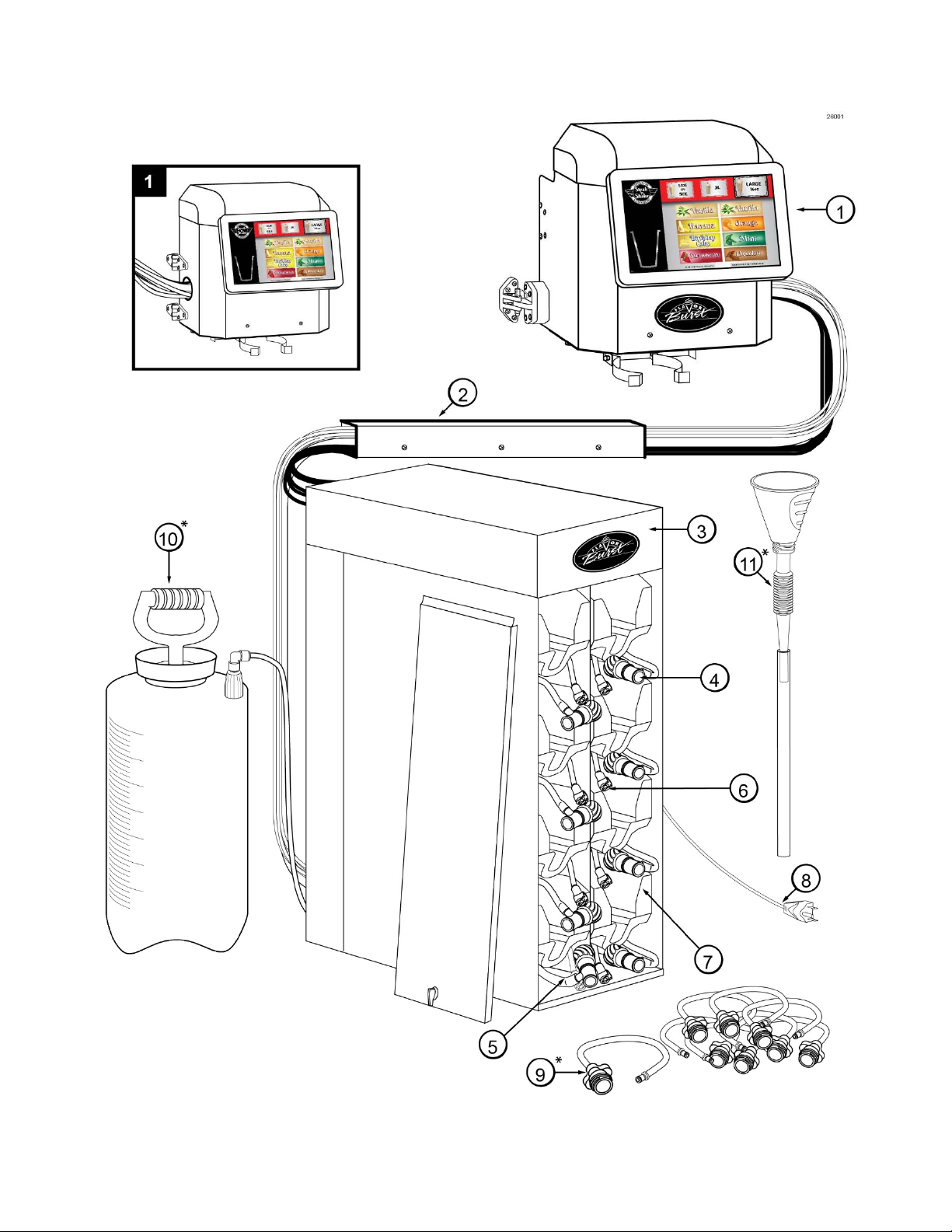
The SNS series system is an add-on flavoring
system compatible with a specific ice cream
freezer. It is designed to dispense concentrated
flavorings next to the ice cream product as it is
dispensed. Dispensing a serving using the
Flavor Burst system is very simple. Simply
place the cup into the cup holder, select a size
and flavor from the Touch Panel, and touch the
dispense button on the screen. The Flavor
Burst system will signal the freezer to dispense
ice cream product as it is dispensing the syrup
at the same time.
Flavor Burst® compatible syrup is stored within
the equipment cabinet in 1 gallon disposable
bags. Proper syrup dispense rate is maintained
by adjusting the flavor level on the Touch
Panel. See the Color Touch Panel Manual for
instructions and features related to the Panel.
Components of the Flavor Burst system should
be cleaned daily to ensure the highest standard
of sanitation. When your equipment is
delivered or if it has been unused for more than
24 hours, follow the DAILY OPENING
PROCEDURES.
The CTP 80SNS-R system attaches to the right
side of the freezer, while the CTP 80SNS-L is
designed to attach to the left side. When used
together, they share the same sanitizer tank,
flush adapters, and funnel. Additional hardware
may be included with the CTP 80SNS-L
system.
NOTE: EQUIPMENT AND PRODUCT
IMAGES IN THIS MANUAL MAY DIFFER
SLIGHTLY FROM YOUR CURRENT SETUP.
Always follow these safety precautions when
operating the Flavor Burst® system:
DO NOT operate the system without
reading this operator’s manual. Failure to follow
this instruction may result in equipment
damage, poor system performance, health
hazards, or personal injury.
DO NOT operate the system unless it is
properly grounded. Failure to follow this
instruction may result in electrocution.
DO NOT operate the system with larger
fuses than specified on the system data label.
Failure to follow this instruction may result in
electrocution or damage to the machine.
Consult your electrician.
DO NOT put objects or fingers near the
door spout area. Failure to follow this instruction
may result in contaminated product or personal
injury from blade contact.
The Flavor Burst cabinet system must be
placed on a level surface capable of supporting
at least 220 lbs of weight. Failure to comply
may result in personal injury or equipment
damage.
DO NOT place more than 25 lbs of
weight on top of the FB 80M cabinet. Failure to
comply may result in personal injury or
equipment damage.
Operate unit under normal ambient
temperatures between 60 and 80 degrees
Fahrenheit. Unit should never be exposed to
freezing temperatures.
INTRODUCTION
INTRODUCTION SAFETY PRECAUTIONS

5
DO NOT install the unit in an area where
a water jet could be used, and do not use a
water jet to clean or rinse the system. Failure to
follow these instructions may result in serious
electrical shock.
HAZARD COMMUNICATION STANDARD
(HCS) – The procedure(s) in this manual
include the use of chemical products. These
chemical products will be highlighted in
bold-faced letters followed by the
abbreviation (HCS) in the text portion of the
procedure. See the Hazard Communication
Standard (HCS) manual for the appropriate
Material Safety Data Sheet(s) (MSDS).
NOISE LEVEL: Airborne noise emission
does not exceed 70 dB(A) when measured at a
distance of 1.0 meter from the surface of the
machine and at a height of 1.6 meters from the
floor.
NOTE: Operations Manual subject to
change. Contact your local distributor for most
recent updates concerning the Flavor Burst
unit.
NOTE: Access to the service area is
restricted to persons having safety / hygiene
knowledge and practical experience of the
appliance.
NOTE: This appliance can be used by
children aged from 8 years and above and
persons with reduced physical, sensory, or
mental capabilities or lack of experience and
knowledge if they have been given supervision
or instruction concerning use of the appliance in
a safe way and understand the hazards
involved.
NOTE: Children shall not play with the
appliance.
NOTE: Cleaning and user maintenance
shall not be made by children without
supervision.
NOTE: Operate unit under normal
ambient temperatures between 60 and 80
degrees Fahrenheit. Unit should never be
exposed to freezing temperatures.
ENVIRONMENTAL NOTICES
If the crossed out wheeled bin symbol is affixed to this product, it signifies that this product
is compliant with the EU Directive for Waste Electric/Electronic Goods (WEEE) as well as
other similar legislation in affect after August 13, 2005. Therefore, it must be collected
separately after is use is completed, and cannot be disposed of as unsorted municipal
waste.
The user is responsible for returning the product to the appropriate collection facility, as specified by your
local codes. For additional information regarding applicable local laws, please contact the municipal
facility and/or local distributor.

6
PAGE INTENTIONALLY LEFT BLANK

7
General System Overview (See Figure 1)
ITEM PART NO. DESCRIPTION QTY. FUNCTION
1 FAC 900R
TOUCH PANEL DOOR
ASSEMBLY – SNS SYSTEM –
RIGHT SIDE
1 RIGHT ASSEMBLY INSTALL: Right side
Flavor Burst SNS unit command center.
1 FAC 900L
TOUCH PANEL DOOR
ASSEMBLY – SNS SYSTEM –
LEFT SIDE
1 LEFT ASSEMBLY INSTALL: Left side
Flavor Burst SNS unit command center.
2 MIS 3519
STAINLESS TUBE / CABLE
CASING ASSEMBLY – SNS
SYSTEM
1 Attaches the flavor lines and/or cables to the
side of the freezer.
3 N/A FLAVOR BURST SNS CABINET
ASSEMBLY 1 Houses syrup trays and bags.
4 SYR 944SNS
SYRUP BAG CONNECTOR
ASSEMBLY FOR THINNER
SYRUPS
7 Transports the thinner syrups (except
chocolate) from the bag to the pumps.
5 SYR 944SNS-C
SYRUP BAG CONNECTOR
ASSEMBLY FOR CHOCOLATE
SYRUP
1 Transports chocolate syrup from the bag to
the pumps.
6 MIS 3028SNS SNS INTERNAL FLUSH LINE
ASSEMBLY 8 Transports sanitizer from the sanitizer tank to
the sanitizer adapter.
7 CAB 113SNS FLAVOR TRAY - SNS 8 Houses syrup bags.
8 ELE 434 POWER CABLE 1 Supplies the electronics board with power.
9* MIS 3029* SNS FLUSH ADAPTER
ASSEMBLY 8
Connects the internal flush line assembly to
the syrup line in order to sanitize the flavor
line.
10* SAN 740* SANITIZER TANK ASSEMBLY 1 Houses sanitizer cleaning solution.
11* MIS 3533A* SNS FUNNEL ASSEMBLY 1 Collects and carries discarded syrup and
sanitizer solution from the cupholder to a bin.
* NOTE: Not included with FAC 900L “left” system when system is purchased with the Dual System Promo.
PARTS IDENTIFICATION / FUNCTIONS

8
General System Overview
Figure 1

9
Cabinet – (See Figure 2)
ITEM PART NO. DESCRIPTION QTY. FUNCTION
1 N/A ELECTRONICS SYSTEM 1 Control system for the unit.
2 CAB 135R-SNS RIGHT SIDE PANEL - SNS 1 Right outer wall of the cabinet.
3 CAB 145 TRAY SUPPORT BRACKET 16 Supports trays and flavor / sanitizer tubes.
4 FAS 2024 8-32 X 1/4 PAN HEAD 28 Attaches various panels of the cabinet.
5 FAS 2014 8-32 X 1/2" PAN HEAD 25 Attaches various panels of the cabinet.
6 SYR 944SNS SYRUP TUBE ASSEMBLY –
SNS SOFT SERVE 7 Transports syrup from bag to pump.
7 ELE 932 PUMP & SANITIZER CABLE
HARNESS 1 Provides power to the syrup and sanitizer
pumps.
8 MIS 3067 #2874 OPEN/CLOSED BUSHING 1 Protects flush tube.
9 SYR 944SNS-C SYRUP TUBE ASSEMBLY –
CHOCOLATE 1 Transports chocolate syrup from bag to pump.
10 CAB 139 FRONT DOOR PANEL 1 Provides access to syrups and connectors.
11 CAB 136-SNS REAR PUMP COVER - SNS 1 Back panel to cover pumps.
12 MIS 3218 CLOSURE PLUG 5/8 INCH 1 Closes up extra opening in the base panel.
13 CAB 134-SNS DIVIDER PANEL - SNS 1 Holds tray support brackets and divides trays.
14 CAB 144R RIGHT PANEL BRACKET 3 Holds tray support rails.
15 CAB 144L LEFT PANEL BRACKET 3 Holds tray support rails.
16 CAB 143 LATCH BRACKET 1 Provides latching tab for front panel latch.
17 FAS 2001 FRONT DOOR PANEL LATCH 1 Latches front door to cabinet front.
18 MIS 3188 CABINET UNIT OPEN CLOSE
BUSHING 1 Protects the 8-Tube Assembly exiting cabinet.
19 N/A PERISTALTIC SYRUP PUMP
A
SSEMBLY
–
SNS CHOCOLATE 1 Pumps chocolate / thick syrups from flavor
ba
g
into flavor line.
20 N/A PERISTALTIC SYRUP PUMP
A
SSEMBLY- SNS 7 Pumps syrup from flavor bags into flavor lines.
21 CAB 155L-SNS PUMP MOUNTING STRIP LEFT -
SNS 1 Support for syrup trays and spacing between
panels.
22 CAB 155R PUMP MOUNTING STRIP RIGHT
- SNS 1 Support for syrup trays and spacing between
panels.
23 CAB 545 SYRUP BOX RAIL GEN NEXT 8 Supports trays and the tray support brackets.
24 MIS 3029 SNS FLUSH ADAPTER
A
SSEMBLY 8 Connects the cabinet flush lines to the syrup
ba
g
connectors.
25 MIS 3028SNS SNS INTERNAL FLUSH LINE
A
SSEMBLY 8 Transports sanitizer from the sanitizer tank to
the sanitizer adapter.
26 N/A TRAY RAMPS 16 Props up the trays to cause the syrup to flow
down towards the ba
g
fitment.
27 FIX 1033 1/4" X 1/4" BLKHD (PUSH-TO-
CONNECT
)
1 Connects Sanitizer Tank tube to the unit.
28 MIS 3030 INTERNAL SANITIZER TUBE
A
SSEMBLY 1 Transports sanitizer solution from the tank to
the flavor lines and pumps.
29 CAB 133 BASE PANEL 1 The foundational panel of the cabinet.
30 RUB 618 RUBBER BUMPER W/ WASHER 6 Provides spacing between under the cabinet.

10
Cabinet (Continued)
ITEM PART NO. DESCRIPTION QTY. FUNCTION
31 FAS 2035 8-32 NUTS - EXT. LOCK WASHER 6 Attaches screw and secures rubber bumper.
32 MIS 3074 SHORTY PLUG #1672 6 Covers screw hole in rubber bumper.
33 FAS 2040 6-32 X 1/4" TAPPING SCREW 24 Secures tray support bracket to side panels.
34 CAB 135L-SNS LEFT SIDE PANEL - SNS 1 Left outer wall of the cabinet.
35 TUB 803 10' 8-TUBE ASSEMBLY TUBE 7 Brings syrup from pump (#1-7) to Door
A
ssembl
y
.
36 TUB 803-SNS-8 8' 8-TUBE ASSEMBLY TUBE -
LARGE 1 Brings thicker syrup from pump #8 to Door
A
ssembl
y
.
Figure 2

11
Door Facade Assembly – Exterior Features (See Figure 3A)
ITEM PART NO. DESCRIPTION QTY. FUNCTION
1 N/A INTERNAL DOOR ASSEMBLY
FEATURES 1 See Figure 3B
2 MIS 3516A SNS LID COVER ASSEMBLY 1 Protects the top of the Door Assembly.
2A MIS 3516 SNS LID COVER BLACK 1 Protects the top of the Door Assembly.
2B MIS 3521A SNS LID BRACKET FRONT
LATCHING 1 Depresses the micro switch, signaling the lid
is in place on the Door Assembl
y
.
2C MIS 3521 SNS LID BRACKET 2 Allow the lid to rest on top of the door façade.
2D FAS 2018 CLAMPING KNOB WASHERS 2 Creates space between the lid and bracket.
2E FAS 2024 8-32 X 1/4 PAN HEAD SCREW 4 Attaches brackets to lid cover.
2F FAS 2014 8-32 X 1/2" PAN HEAD SCREW 2 Attaches bracket to lid cover.
3 MIS 3525R SNS FACADE FACE RIGHT 1 RIGHT ASSEMBLY INSTALL: Main outer
panel of “ri
g
ht” Door Assembl
y
.
3 MIS 3525L SNS FACADE FACE LEFT 1 LEFT ASSEMBLY INSTALL: Main outer
panel of “left” Door Assembl
y
.
4 ELE 906SNS F10 DRIVER BOARD CTP - SNS 1 Flavor Burst unit command center.
5 MIS 3526 FACADE CTP MOUNT SNS 1 Mounts Touch Panel to front of Door panel.
6 MIS 3150 FLAVOR BURST LOGO DECAL 1 Displays Flavor Burst trademark logo.
7 MIS 3528 3.5 MM MALE - MALE CABLE 26"
SNS 1 Electronically connects Touch Panel to
freezer.
8 ELE 427SNS MICRO SWITCH CABLE - SNS 1 Electronically connects the micro switch of
the lid to the Touch Panel.
9 ELE 462 V7-3S17D8-022 MICRO SWITCH SNS 1 Signals the Touch Panel whether or not the
lid is in place.
10 FAS 2140 4-40 x 5/8" PHILLIPS PH S.S. SCREW 2 Fastens the micro switch to the Door panel.
11 MIS 3210 1" OPEN CLOSE BUSHING 1 Protects the Touch Panel cables around the
Door panel openin
g
.
12 MIS 3518 HEYCO 246 2" HOLE BUSHING 1 Protects the Touch Panel cables and tubes
around the Door panel openin
g
.
13 FAS 2136 10-32 TWO PIECE HEX CAPNUTS 14 Caps the ends of various screws.
14 FAS 2064 10-32 X 3/8 S.S. PHLP PH M/SCREW 14 Attaches brackets and hinges to Door panel.
15 FAS 2139 M4 x 6 PHILLIPS PH S.S. SCREW 4 Attaches mounting bracket to Touch Panel.
16 FAS 2177 10-32 NYLON LOCK NUT ST/ST 4 Locks and protects the ends of screws.
17 FAS 2007 MOTOR MOUNTING HOUSING
SCREW 2 Attaches upper frame to Door panel.
18 MIS 3502 S3822-0100 HINGE SNS 2 Allows the Door Assembly to swing open
awa
y
from freezer door.
19 MIS 3508 HINGE SPACERS BLACK SNS 1 Provides more depth to the latch.
20 MIS 3501 S3824-1075 HINGES SNS (2pc) 1 Locks Door Assembly against the freezer.
21 FAS 2022 8-18 X 1/2 PAN HEAD-SELF DRILL 7
LEFT ASSEMBLY INSTALL: Attaches door
latch and tube rail to freezer where pre-
drilled holes are not available.
22 MIS 3517 DETENT PIN 1/4 x 3/4 SS316PL 1 Locks the two Door Assembly latch pieces.
23 MIS 3527 12" STAINLESS TETHER WIRE SNS 1 Keeps the detent pin tethered to the latch.

12
Door Facade Assembly – Exterior Features (Continued)
ITEM PART NO. DESCRIPTION QTY. FUNCTION
24 FAS 2135 10-32 x 5/8 TRUSS PHILLIPS MS
SCREW 4 Secures the receiving latch part to the
freezer.
25 FAS 2191 10-32 x 1" PHILLIPS PH S.S. SCREW 4 Secures the Door’s latch to the Door
A
ssembl
y
.
26 MIS 3519 STAINLESS TUBE / CABLE CASING
A
SSEMBLY
–
SNS SYSTEM 1 Channels and protects the tubes and
cables alon
g
the side of the freezer.
26A MIS 3519A SNS TUBE RAILING RESTRAINT A -
BRACKET 1 Holds the tubes and cables.
26B MIS 3519B SNS TUBE RAILING RESTRAINT B -
COVER 1 Covers and closes the tube railing
assembl
y
.
26C N/A ADHESIVE SEAL 1
Seals gap between rail assembly and
freezer to prevent buildup of foreign
material.
26D FAS 2064 10-32 X 3/8 S.S. PHLP PH M/SCREW 3 Secures the rail cover against the base.
26E FAS 2135 10-32 x 5/8 TRUSS PHILLIPS MS 3 Attaches the tube rail assembly to the
freezer.
27 FAS 2042 4/40 LOCK NUTS 04NK 2 Secures the micro switch to the door
façade.
28 TUB 803 10' 8-TUBE ASSEMBLY TUBE 7 Brings syrup from pump (#1-7) to Door
A
ssembl
y
.
29 TUB 803-SNS-8 8' 8-TUBE ASSEMBLY TUBE - LARGE 1 Brings thicker syrup from pump #8 to
Door Assembl
y
.

13
PAGE INTENTIONALLY LEFT BLANK

14
Door Facade Assembly – Exterior Features
Figure 3A

15
Door Facade Assembly – Interior Features (See Figure 3B)
ITEM PART NO. DESCRIPTION QTY. FUNCTION
1 N/A EXTERNAL DOOR ASSEMBLY
FEATURES 1 See Figure 3A
2 MIS 3520-R CUP HOLDER ASSEMBLY RIGHT -
SNS 1 RIGHT ASSEMBLY INSTALL: Holds serving
cup and funnel under spout.
2A MIS 3520A CUP HOLDER FRAME SNS 1 ea. Attaches cup holder spring arms to bracket.
2B MIS 3520B CUP HOLDER SPRING SNS 2 ea. Holds the cup / funnel in place.
2C FAS 2136 10-32 TWO PIECE HEX CAPNUTS 4 ea. Covers the ends of the screws.
2D MIS 3520D-R CUP HOLDER SUPPORT B RIGHT 1 ea. Main bracket arm of left cup holder assembly.
2E FAS 2064 10-32 X 3/8 S.S. PHLP PH SCREW 2 ea. Secures the spring arms to the frame.
2 MIS 3520-L CUP HOLDER ASSEMBLY LEFT -
SNS 1 LEFT ASSEMBLY INSTALL: Holds serving
cup and funnel under spout.
2A MIS 3520A CUP HOLDER FRAME SNS 1 ea. Attaches cup holder spring arms to bracket.
2B MIS 3520B CUP HOLDER SPRING SNS 2 ea. Holds the cup / funnel in place.
2C FAS 2136 10-32 TWO PIECE HEX CAPNUTS 4 ea. Covers the ends of the screws.
2D MIS 3520D-L CUP HOLDER SUPPORT B LEFT 1 ea. Main bracket arm of left cup holder assembly.
2E FAS 2064 10-32 X 3/8 S.S. PHLP PH SCREW 2 ea. Secures the spring arms to the frame.
3 MIS 3524 MOUNT FACADE FRAME SNS 2 Supports inner plates of Door Assembly.
4 MIS 3529 MOUNT PLATE - TOP 1 Supports upper parts inside Door Assembly.
5 MIS 3530 MOUNT PLATE - MIDDLE 1 Supports middle parts inside Door Assembly.
6 MIS 3531A LOWER SPLASH PANEL
A
SSEMBLY - REVERSIBLE 1 Covers and protects bottom of Door
A
ssembl
y
.
6
A
MIS 3531 MOUNT PLATE - BOTTOM 1 Protects bottom of Door Assembly.
6B FAS 2185 1/4 x 1" L THUMBSCREW - SNS 2 Allows for lower plate to be removed easily.
6C FAS 2188 SNS SPACER 16FW250125 2 Allows for space between the middle and
bottom plates of the Door Assembl
y
.
6D FAS 2190 RETAINER RING TY-21SS 2 Holds the thumbscrew in place.
7 MIS 3503A ST MODEL LINEAR ACTUATOR
A
SSEMBLY - SNS 1 Lifts the freezer draw pin when activated.
8 FAS 2187 STAINLESS BOLT FOR LIFT PLATE 1 Connects the auto draw linear actuator to the
lift adapter bracket.
9 MIS 3505 COTTER PIN, HAIRPIN, 11/64" 1 Secures the lower end of the linear actuator
under the middle panel.
10 MIS 3522 SNS LIFT ADAPTER 1 Plate that connects the linear actuator to the
freezer draw pin.
11 FAS 2199 1/4 x 1/2" L THUMBSCREW SNS 1 Secures lift bracket to freezer draw bracket.
12 FAS 2190 RETAINER RING TY-21SS 4 Holds the thumbscrew in place.
13 MIS 3504 QL-55 LOAD CELL 20KG
CAPACITY 1 Measures the weight of object connected to
the cup holder.
14 MIS 3523 SNS LOAD CELL MOUNT 1 Mounts the weight sensor to the middle plate
of the Door Assembl
y
.
15 MIS 3534 CABLE CLAMP 1 Secures the Load Cell cable in place.
16 FAS 2197 10-32 x 7/8 PHILLIPS PH SCREW 2 Attaches cup holder to weight sensor.
17 FAS 2007 10-32 X 1/2" PAN HEAD SCREW 10 Attaches the mounting plate to the middle
plate of the Door Assembl
y
.

16
Door Facade Assembly – Interior Features (Continued)
ITEM PART NO. DESCRIPTION QTY. FUNCTION
18 FAS 2136 10-32 TWO PIECE HEX CAPNUTS 8 Covers the ends of the screws.
19 FAS 2192 10-32 x 1 1/4 PHILLIPS PH S.S.
SCREW 2 Attaches the spacers to the weight sensor.
20 FAS 2188 SNS SPACER 16FW250125 8
Allows for space between the middle and
bottom plates of the Door Assembly and load
cell bracket.
21 SYR 902 21.5"X3/16IDX1/4OD FLAVOR-IN – 2” 7 Connects the elbow fitments to the check
valves of the flavor lines.
22 TUB 805 1/2" OD x 3/8" ID DELRIN TUBE – 2” 1 Connects the elbow fitments to the check
valves of the flavor line
(
thick s
y
rup
)
.
23 MIS 3520C-R CUP HOLDER SUPPORT A LEFT 1 RIGHT ASSEMBLY INSTALL: Attaches left
cup holder to the wei
g
ht sensor.
23 MIS 3520C-L CUP HOLDER SUPPORT A LEFT 1 LEFT ASSEMBLY INSTALL: Attaches left
cup holder to the wei
g
ht sensor.
24 MIS 3532A SNS ALUMINUM DRIP SHIELD
A
SSEMBLY 1 Protects inside of Door Assembly around
spout.
24A MIS 3532 SNS ALUMINUM DRIP SHIELD 1 Protects inside of Door Assembly from
product.
24B FAS 2014 8-32 X 1/2" PAN HEAD SCREW 4 Attaches drip shield to top and middle plates.
24C FAS 2035 8-32 NUTS - EXT. LOCK WASHER 2 Locks the drip shield screws in place.
25 MIS 3514 100 G SCALE CALIBRATION
WEIGHT 1 Used to calibrate the Touch Panel’s weight
sensor pro
g
rammin
g
with the cup holder.
26 FAS 2193 1/4 - 20 x 5/8" PHILLIPS PH SCREW 8 Secures the top plate to the Door Assembly
lower frame.
27 MIS 3510 316 STAINLESS STEEL TUBE 4"
SNS 3 Shorter tubes that channel syrup as it exits
Door Assembl
y
near spout.
28 MIS 3511 316 STAINLESS STEEL TUBE 5.25"
SNS 2 Tubes that channel syrup as it exits Door
A
ssembl
y
near spout.
29 MIS 3512 316 STAINLESS STEEL TUBE 6"
SNS 2 Longer tubes that channel syrup as it exits
Door Assembl
y
near spout.
30 MIS 3513 316 STAINLESS STEEL TUBE 4.75"
SNS 1 Thicker tube that channels thick / chocolate
s
y
rup as it exits Door Assembl
y
near spout.
31 FIX 1503 3/8 x 1/2 UNION ELBOW SNS 1 Connects the large syrup valve to the large
metal s
y
rup tube
(
thick / chocolate s
y
rup
)
.
32 FIX 1509 1/2" OD CHECK VALVE TRUESEAL
SNS 1 Provides a 1-way flow of syrup (thick /
chocolate s
y
rup
)
.
33 FIX 1036 1/4" TO 1/4" OD UNION ELBOW 7 Connects syrup valve to metal syrup tube
(
thick / chocolate s
y
rup
)
.
34 FIX 1063 GEN NEXT CHECK VALVE 1/4SCV 7 Provides a 1-way flow of syrup.
35 FIX 1061GN 1/4 x 1/4 STEM ELBOW GN 2 Creates a right angle for the syrup line.
36 FAS 2064 10-32 X 3/8 S.S. PHLP PH M/SCREW 3 Secures the steel clamp to the support frame.
37 FAS 2081 STEEL CABLE CLAMPS 3 Secures various cables to the support frame.
38 MIS 3153 EDGE PROTECTORS - BLACK 2 Covers more exposed edges of support
frame.
39 FAS 2194 #10 INTERNAL TOOTH LOCK
WASHER 2 Locks the screws to the weight sensor.

17
ITEM PART NO. DESCRIPTION QTY. FUNCTION
40 FAS 2067 1/4" PLASTIC WASHER 1 Secures the thumbscrew of the lift bracket to
freezer draw bracket.
41 RUB 673 00 FLAT WASHER ½” OD 1 Secures the thumbscrew of the lift bracket to
freezer draw bracket.

18
Door Facade Assembly – Interior Features
Figure 3B

19
Syrup Pump and Related Parts (See Figure 4)
ITEM PART NO. DESCRIPTION QTY. FUNCTION
1 N/A SOFT SERVE SYRUP PUMP
A
SSEMBLY 8 Pumps syrup from flavor bags to flavor lines.
1A SYR 926-SNS SOFT SERVE SYRUP PUMP 1 ea. Pumps syrup from flavor bags to flavor lines.
1B TUB 809T 1/4"ID SHAKE PUMP REPL.
TUBE 1 ea. Transports syrup through pump.
1C FAS 2137 FCB HOSE CLAMP 22HC0468 4 ea. Secures pump tubes to hose barbs.
1D FIX 1506 5/16 TO 5/16 TUBE TO HOSE
BARB 2 ea. Connects syrup pump to flavor line elbow
connectors.
2 ELE 932 PUMP & SANITIZER CABLE
HARNESS 1 Provides power to the syrup pumps.
3 SYR 944SNS SYRUP LINE ASSEMBLY FOR
PUMPS #1-7 - SNS 7 Transports syrup and sanitizer from the
connector to the pumps for tra
y
s #1-7.
3A SYR 928SNS ENCORE PCSS FITMENT
GREEN SNS 1 ea. Connects syrup bag to syrup line.
3B TUB 811 TUBE-SILICONE .188X.375 PE
FB80 5” 1 ea. Connects barb fitment to tube port.
3C FIX 1048 FITTING-1/4x1/4 BARB FB80 1 ea. Connects syrup tube to silicone tube.
3D SYR 902 FLAVOR-IN TUBE 1 ea. Carries syrup from syrup bag (#1-7) to pump
(
#1-7
)
.
4 SYR 944SNS-C SYRUP LINE ASSEMBLY FOR
PUMP #8 - SNS 1 Transports syrup and sanitizer from the
connector to the pump for tra
y
s #8.
4A SYR 928SNS ENCORE PCSS FITMENT
GREEN SNS 1 ea. Connects syrup bag to syrup line.
4B FAS 2196 SNS CHOCOLATE LINE HOSE
CLAMP 1 ea. Clamps the flavor tube to the flavor connector
for s
y
rup line #8.
4C SYR 902-SNS FLAVOR-IN TUBE - SNS 1 ea. Carries syrup from syrup bag to pump #8.
5 FIX 1504 1/4 x 5/16 UNION ELBOW SNS 14
Provides a right-angle connection from the
pump to the syrup lines #1-7 and syrup tubes
of the 8-Tube Assembl
y
.
6 FIX 1502 3/8 x 3/8 UNION ELBOW SNS 1 Provides a right-angle connection from the
pump #8 to the s
y
rup line.
7 FIX 1503 3/8 x 1/2 UNION ELBOW SNS 1 Provides a right-angle connection from the
pump #8 to the s
y
rup line.
8 FIX 1505 3/8 STEM HOSE TO BARB
SNS 1 Connects the syrup tube #8 to the elbow
fitment of the s
y
rup pump #8.
9 FIX 1501 1/2 x 1/2 UNION ELBOW SNS 1 Provides a right-angle connection for the larger
s
y
rup tube of the 8-Tube Assembl
y
.
10 TUB 803-SNS 3/8" x 1/2" LDPE NATURAL
TUBING 1 Connects the syrup pump to the elbow fitment
of the lar
g
er s
y
rup tube of 8-Tube Assembl
y
.
11 TUB 803 10' 8-TUBE ASSEMBLY TUBE 7 Brings syrup from pump (#1-7) to Door
A
ssembl
y
.
12 TUB 803-SNS-8 8’' 8-TUBE ASSEMBLY TUBE -
LARGE 1 Brings thicker syrup from pump #8 to Door
A
ssembl
y
.
13 CAB 113SNS FLAVORING TRAY - SNS 8 Houses syrup bags.
This manual suits for next models
1
Table of contents