Fleck 5600SE User manual

IMPORTANT: Fill in pertinent information on page 2 for future reference.
MODEL 5600SE
Upflow Brining
Service Manual

MODEL 5600SE Upflow
Job Specification Sheet
Printed in U.S.A.
Job Number ____________________________________________________________
Model Number __________________________________________________________
Water Test______________________________________________________________
Capacity Of Unit__________________________Ma ._______________________Per Regeneration
Mineral Tank Size: Diameter _________________________Height _________________________________
Under Bedding ____________________________ Amount______________________________________
Type Of Media ____________________________ Cubic Feet __________________________________
Brine Tank Size ________________________________________________________________________
Salt Setting Per Regeneration _____________________________________________________________
Page 2
Valve Programming
Treated Water Capacity ______________________________ (Gallons / Liters)
Regeneration Day Override _______________________________ (Ma . Days Between Regen.)
Regeneration Time ________________________________ ( A.M. ) ( P.M. )
Notes:
________________________________________________________________________________
________________________________________________________________________________
________________________________________________________________________________
________________________________________________________________________________
________________________________________________________________________________
________________________________________________________________________________
________________________________________________________________________________
________________________________________________________________________________

Printed in U.S.A.
Page 3
MODEL 5600SE Upflow
General Residential Installation Check List
WAT R PR SSUR : A minimum of 25 pounds of water pressure is required for regeneration valve to operate
effectively.
L CTRICAL FACILITI S: An uninterrupted alternating current (A/C) supply is required. Please make sure your
voltage supply is compatible with your unit before installation.
XISTING PLUMBING: Condition of e isting plumbing should be free from lime and iron buildup. Piping that is built up
heavily with lime and/or iron should be replaced. If piping is clogged with iron, a separate iron filter unit should be
installed ahead of the water softener.
LOCATION OF SOFT N R AND DRAIN: The softener should be located close to a clean working drain and
connected according to local plumbing codes.
BY-PASS VALV S: Always provide for the installation of a by-pass valve if unit is not equipped with one.
CAUTION: Water pressure is not to e ceed 120 p.s.i., water temperature is not to e ceed 110°F, and the unit cannot be
subjected to freezing conditions.
alve Installation and Start-up Procedures
1. Place the softener tank where you want to install the unit, making sure the tank is level and on a firm base.
2. During cold weather it is recommended that the installer warm the valve up to room temperature before operating.
3. All plumbing should be done in accordance with local plumbing codes. The pipe size for the drain should be a
minimum of 1/2 ″. Backwash flow rates in e cess of 7 gpm or length in e cess of 20′ require 3/4″ drain line.
4. The 1″ distributor tube (1.050 O.D.) should be cut 2.0″ below the top of each tank. Note: Only use silicone lubricant.
5. Lubricate the distributor o-ring seal and tank O-ring seal. Place the main control valve on tank.
6. Solder joints near the drain must be done prior to connecting the Drain Line Flow Control fitting (DLFC). Leave at
least 6″ between the DLFC and solder joints when soldering pipes that are connected on the DLFC. Failure to do
this could cause interior damage to DLFC.
7. Teflon tape is the only sealant to be used on the drain fitting.
8. Make sure that the floor is clean beneath the salt storage tank and that it is level.
9. Place appro imately 1″ of water above the grid plate. If a grid is not utilized, fill to the top of the air check in the salt
tank. Do not add salt to the brine tank at this time.
10. On units with a by-pass, place in by-pass position. Turn on the main water supply. Open a cold soft water tap
nearby and let run a few minutes or until the system is free from foreign material (usually solder) that may have
resulted from the installation. Once clean, close the water tap.
11. Place the by-pass in service position and let water flow into the mineral tank. When water flow stops, slowly open a
cold water tap nearby and let run until the air is purged from the unit. Then close tap.
12. Plug the valve into an approved power source. Once the valve is powered it will drive to the Service Position.
Page 4
Printed in U.S.A.
MODEL 5600SE Upflow
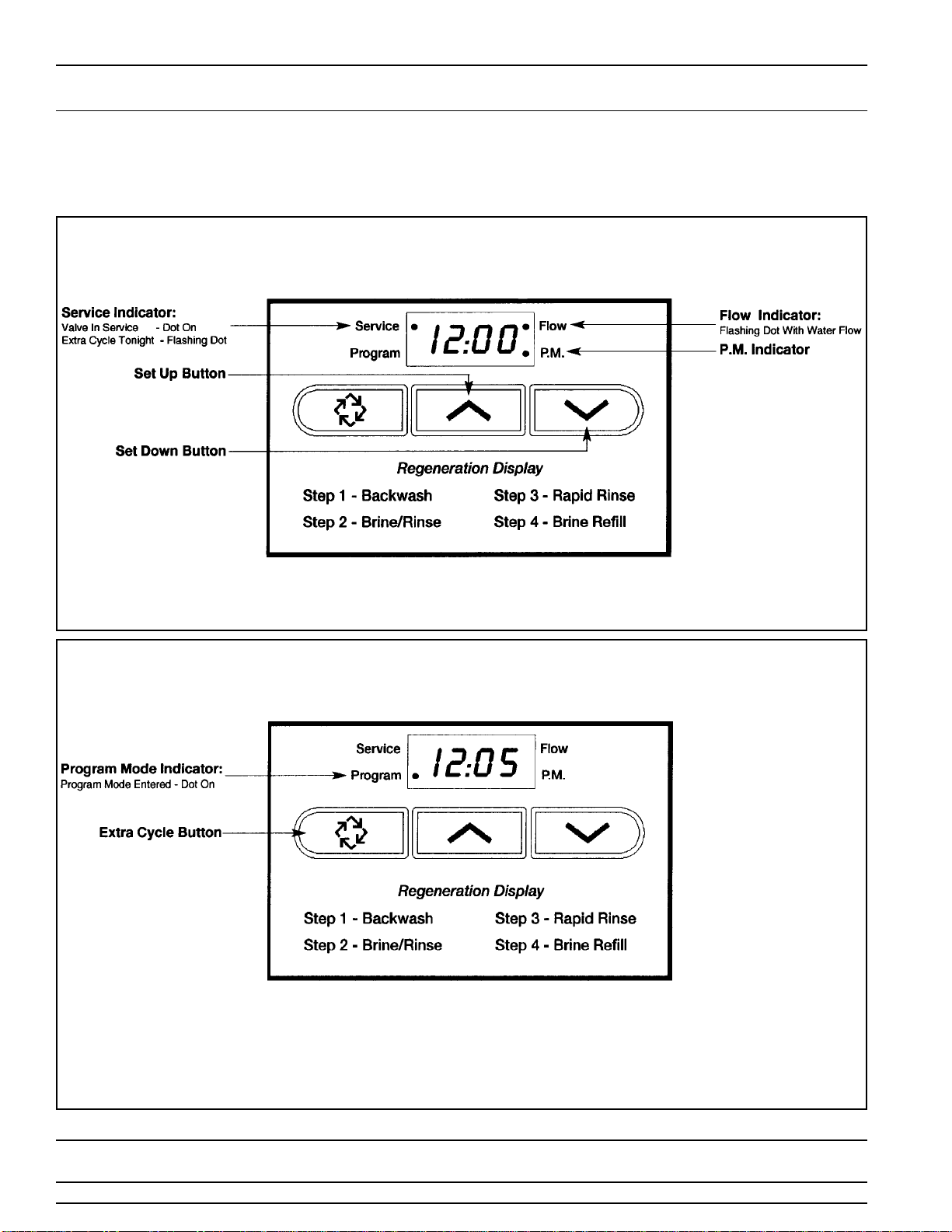
Control Start-up Procedures
Whenever the valve is in
Service
the current time of day can be set, the control programmed, or an
e tra regeneration initiated at any time.
Push either the Up or Down Set Button once to adjust Time Of Day Display by one digit.
Push and hold either Up or Down Set Button to adjust Time Of Day Display by several digits.
1.
Set Time Of Day
1. Push and hold for 5 seconds
both
the Up and down Set Buttons to enter Programming
Mode.
2. Push the E tra
Cycle Button
once per display until all have been viewed and this mode is
e ited and normal operation is resumed.
2. nter Control Programming Mode

Printed in U.S.A.
Page 5
MODEL 5600SE Upflow
Control Start-up Procedures (Cont’d.)
Depending on current control programming, option setting displays that are not required to be set will not be
viewed.
3. Push the E tra Cycle Button. The third option setting display that appears is Regeneration
Day Override. Using the Set Up or Down Buttons, set the ma imum number of days before
a regeneration cycle must occur. For E ample:
4. Control programming is now complete. Push the E tra Cycle Button. This will e it the
control from the Programming Mode, and resume Normal Operation.
1. The first option setting display that appears in the Program Mode is Treated Water
Capacity. Using the Set Up or Down Buttons, set the amount of treated water that can flow
through the unit before a regeneration is required. For E ample:
2. Push the E tra Cycle Button. The second option setting display that appears is
Regeneration time. Using the Set Up or Down Buttons, set the desired time of day when a
regeneration can occur, if required. For E ample:
3. Set Control Programming

Page 6
Printed in U.S.A.
MODEL 5600SE Upflow
Control Start-up Procedures (Cont’d.)
When starting an E tra Cycle, you will have one or two options:
1. Press and Release the xtra Cycle Button:
-With
Immediate Regeneration
controls the control will go into regeneration cycle immediately.
-With
Delayed Regeneration
controls the Service Arrow will begin to flash immediately and a regeneration
will occur at the present regeneration time (i.e. 2:00 a.m.)
2. Press and Hold for 5 seconds the xtra Cycle Button:
- With Delayed Regeneration controls this will force the control to go into regeneration cycle immediately.
The following series of displays appear when the control enters a regeneration cycle:
4. Start An Immediate xtra Cycle
5. Regeneration Cycle Displays

Printed in U.S.A.
Page 7
MODEL 5600SE Upflow
Control Start-up Procedures (Cont’d.)
A. Once the valve reaches Regen Step #1 let water run to drain for about 5 minutes.
Ne t, manually step the valve through a regeneration cycle checking valve operation
in each step:
B. Push the E tra Cycle Button once to advance the valve to Regen Step #2.
C. Push the E tra Cycle Button once to advance the valve to Regen Step #3. (Optional)
D. Push the E tra Cycle Button once to advance the valve to Regen Step #4. (Optional)
With proper valve operation verified:
A. Add water to the top of the air check. Manually step the valve to the Brine Draw Position
and allow the valve to draw water from the brine tank until it stops. Note: The air check will
check at appro imately the midpoint of the screened intake area.
B. Ne t, manually step the valve to the Brine Refill Position and allow the valve to return to
Service automatically.
C. With the valve in Service, check that there is about 1.0″ of water above the grid in the brine
tank, if used.
D. Fill the brine tank with salt.
E. Set-Up is now finished, the control can now be left to run automatically.
6. Fast Cycle Valve Thru Regeneration
7. Final Set-Up
Page 8
Printed in U.S.A.
MODEL 5600SE Upflow
Control Operation
Timeclock Regeneration Valves
In normal operation the Time Of Day Display will be viewed at all times. The control will operate normally until the
number of days since the last regeneration reaches the Regeneration Day Override setting. Once this occurs, a
regeneration cycle will then be initiated at the preset Regeneration Time.
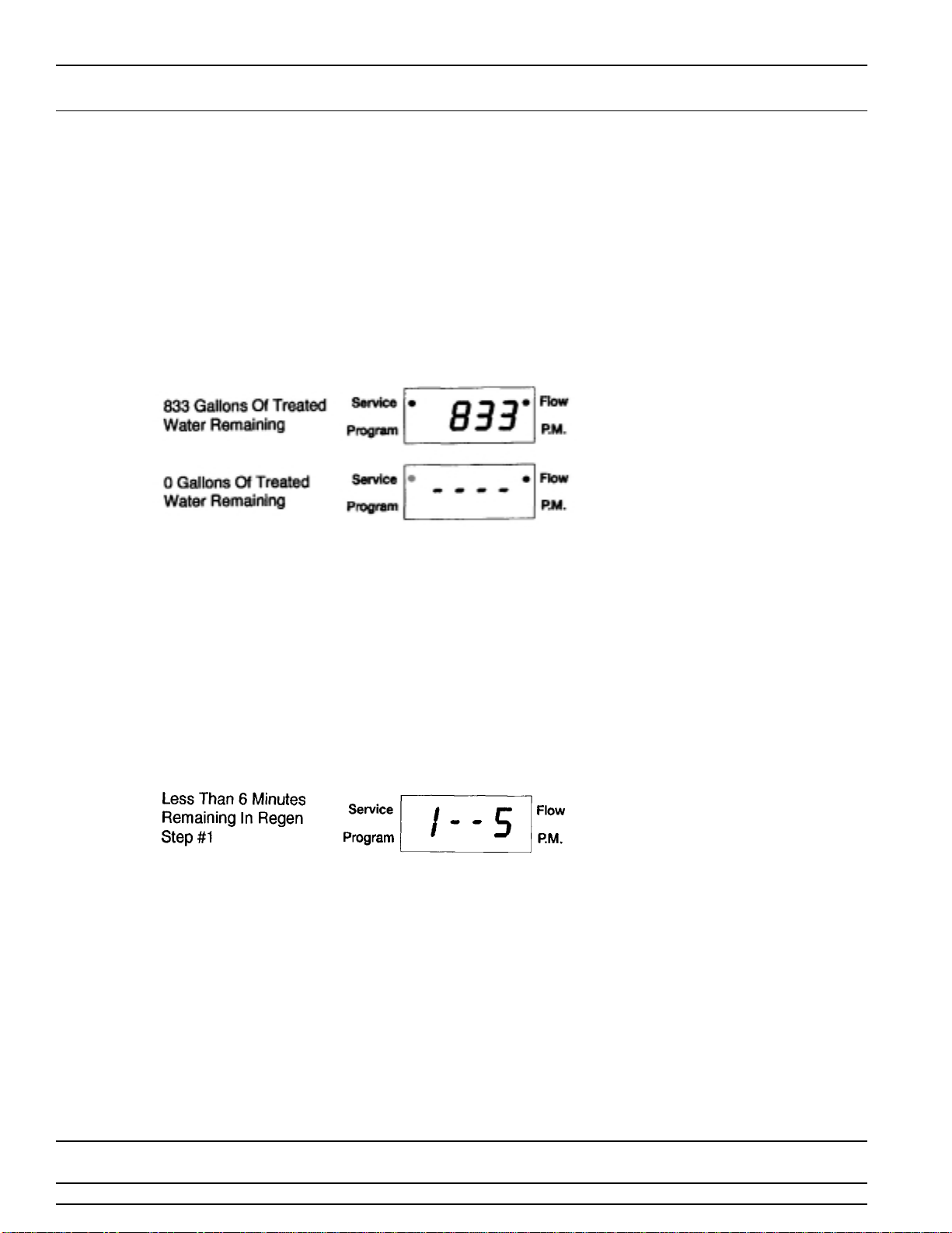
Flow Meter quipped Valves
In normal operation the Time Of Day Display will alternate being viewed with a Volume Remaining Display. This display
will be in gallons. As treated water is used, the Volume Remaining Display will count down from a ma imum value to
zero or (----). Once this occurs a regeneration cycle will then be initiated immediately or delayed to the set
Regeneration Time. Water flow through the valve is indicated by the Flow Dot that will flash in a direct relationship to
flow rate. For E ample:
Immediate Regeneration Valves With Days Between Regeneration Override Set
When the valve reaches its set Days Since Regeneration Override value a regeneration cycle will be initiated
immediately. This event occurs regardless of the Volume Remaining display having reached zero gallons.
Delayed Regeneration Valves With Days Between Regeneration Override Set
When the valve reaches its set Days Since Regeneration Override value a regeneration cycle will be initiated at the
preset Regeneration Time. This event occurs regardless of the Volume Remaining display having reached zero gallons.
Control Operation During Regeneration
In Regeneration the control will display a special
Regeneration Display.
In this display the control will show the current
regeneration step number the valve is advancing to, or has reached, and the time remaining in that step. The step
number displayed will flash until the valve has completed driving to this regeneration step position. Once all
regeneration steps have been completed the valve will return to Service and resume normal operation. For E ample:
Pushing the E tra Cycle Button during a regeneration cycle will immediately advance the valve to the ne t cycle step
position and resume normal step timing.
Control Operation During Programming
The control will only enter the Program Mode with the valve in Service. While in the Program Mode the control will
continue to operate normally monitoring water usage and keeping all displays up to date. Control programming is
stored in memory permanently. There is no need for battery backup power.
Control Operation During A Power Failure
During a power failure all control displays and programming will be stored for use upon power re-application.
The
control will retain these values for years, if necessary, without loss.
The control will be fully inoperative and any calls for
regeneration will be delayed. The control will upon power re-application resume normal operation from the point were it
was interrupted.
An indication that a power outage has occurred will be an inaccurate time of day display
.

Printed in U.S.A.
Page 9
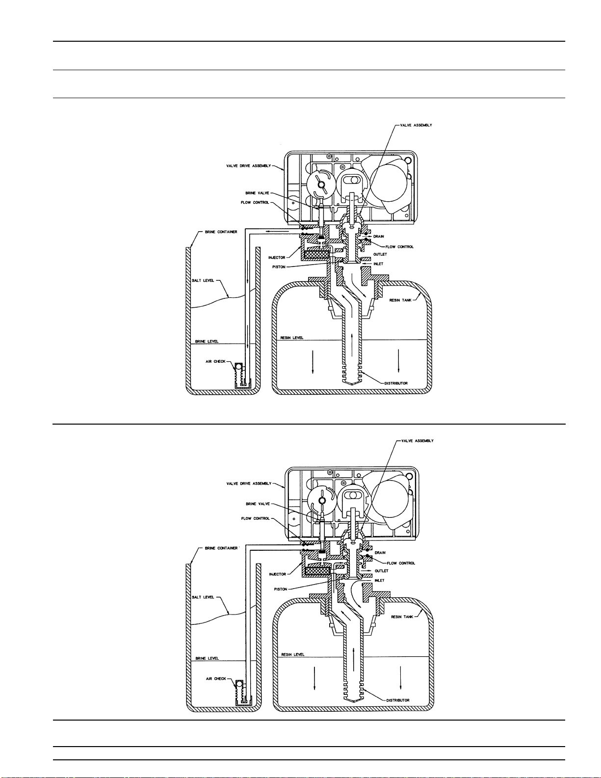
MODEL 5600SE Upflow
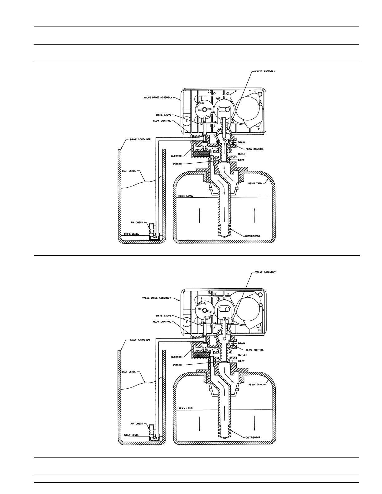
Water Conditioner Flow Diagrams (Upflow Brining)
Using Yellow Cycle Cam (Part No. 24598)
Service
Position
Backwash
Position
(Regeneration Cycle Step #1)

Page 10
Printed in U.S.A.
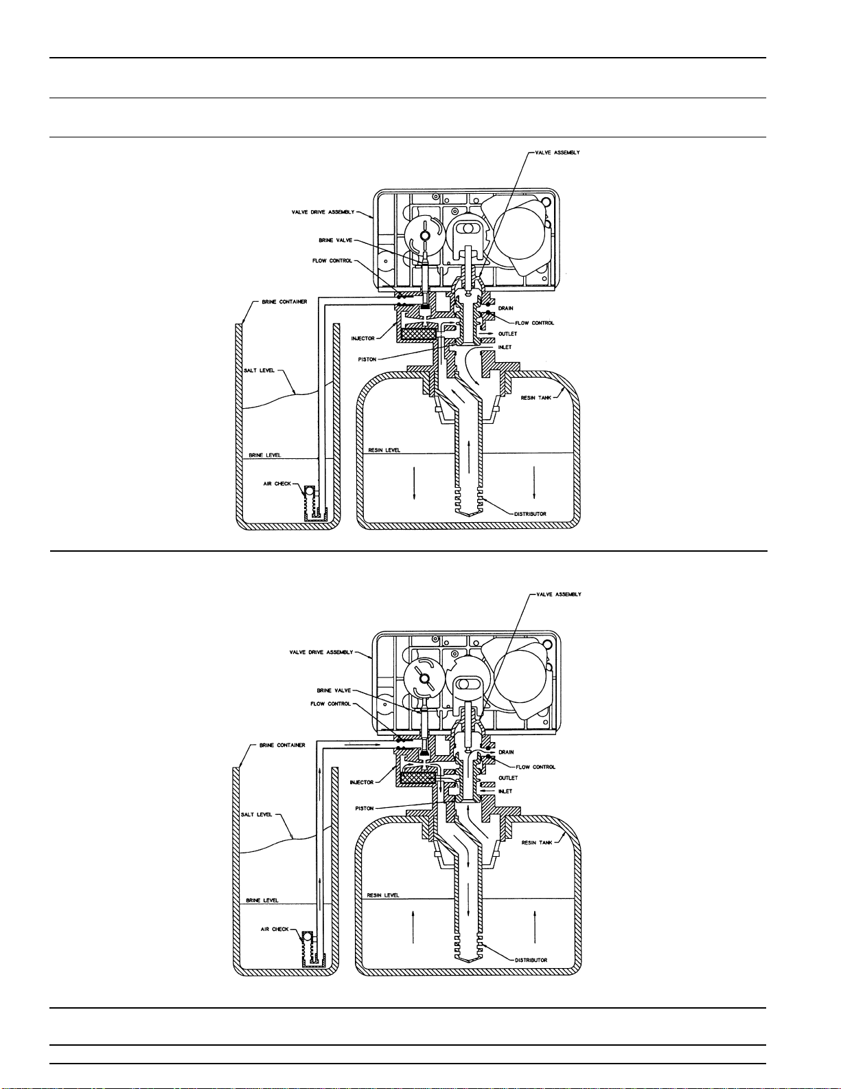
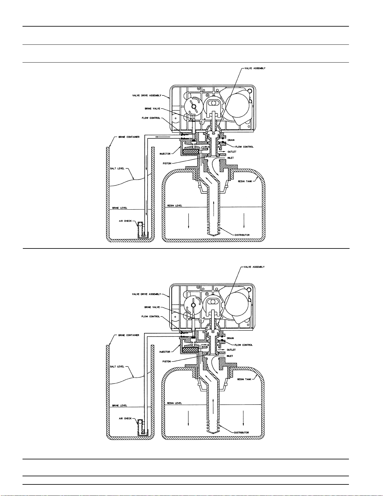
MODEL 5600SE Upflow
Water Conditioner Flow Diagrams (Upflow Brining)
Using Yellow Cycle Cam (Part No. 24598) (Cont’d.)
(Regeneration Cycle Step #2)
Brine/Slow Rinse
Position
Rapid Rinse
Position
(Regeneration Cycle Step #3)
Printed in U.S.A.
Page 11
MODEL 5600SE Upflow
Water Conditioner Flow Diagrams (Upflow Brining)
Using Yellow Cycle Cam (Part No. 24598) (Cont’d.)
(Regeneration Cycle Step #4)
Brine Tank
Fill Position
Service
Position
Page 12
Printed in U.S.A.
MODEL 5600SE Upflow
Water Conditioner Flow Diagrams (Upflow Brining)
Using Red Cycle Cam (Part No. 17885)
Service
Position
Brine/Slow Rinse
Position
(Regeneration Cycle Step #1)
Printed in U.S.A.
Page 13
MODEL 5600SE Upflow
Water Conditioner Flow Diagrams (Upflow Brining)
Using Red Cycle Cam (Part No. 17885)
Backwash
Position
(Regeneration Cycle Step #2)
Rapid Rinse
Position
(Regeneration Cycle Step #3)
Page 14
Printed in U.S.A.
MODEL 5600SE Upflow
Water Conditioner Flow Diagrams (Upflow Brining)
Using Red Cycle Cam (Part No. 17885)
Brine TankFill
Position
(Regeneration Cycle Step #4)
Service
Position

Printed in U.S.A.
Page 15
MODEL 5600SE Upflow
alve Wiring Diagram
CB1 - 5600SE Circuit Board
VDM - Valve Drive Motor
EM - Electronic Flow Meter (Optional)
SW1 - Homing Switch
SW2 - Step Switch
HCAM - Homing Cam
UFSCAM - Upflow Step Cam
Page 16
Printed in U.S.A.
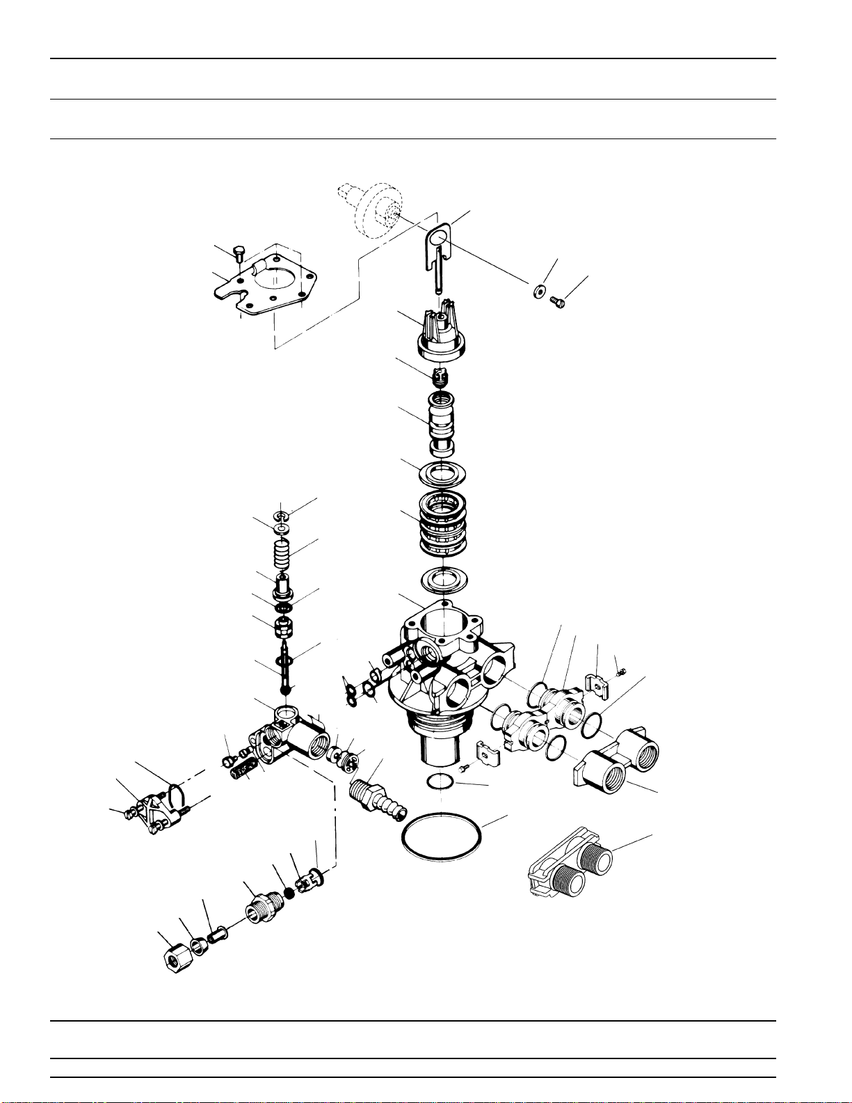
MODEL 5600SE Upflow
Control alve Assembly
(See opposite page for parts list)
61
60
1
2
3
4
7
6
5
11
12
13
14
18
17
16
15
10
22
23
24
28
26
25
20
29
31
39
41
42
43
44
48 47 46 45
49
51
52
53
54
5857 56
55
59
40 54B
58
17
50

Printed in U.S.A.
Page 17
Item No. Quantity Part No. Description
1. . . . . . . . . . . . 1 . . . . . . . . . . . . .61400-31 . . . . . . . . . . . . . . . Valve Body, Up-Flow 13/16″ Distributor
1 . . . . . . . . . . . . .61400-32 . . . . . . . . . . . . . . . Valve Body, Up-Flow 1″ Distributor
2. . . . . . . . . . . . 4 . . . . . . . . . . . . .14241. . . . . . . . . . . . . . . . . . Spacer
3. . . . . . . . . . . . 5 . . . . . . . . . . . . .13242. . . . . . . . . . . . . . . . . . Seal
4. . . . . . . . . . . . 1 . . . . . . . . . . . . .18848. . . . . . . . . . . . . . . . . . Piston - (Used with Yellow or Red Cycle Cam)
5. . . . . . . . . . . . 1 . . . . . . . . . . . . .14309. . . . . . . . . . . . . . . . . . Piston Rod Retainer
6. . . . . . . . . . . . 1 . . . . . . . . . . . . .15561. . . . . . . . . . . . . . . . . . End Plug Assy - White
7. . . . . . . . . . . . 1 . . . . . . . . . . . . .13001-03 . . . . . . . . . . . . . . . Piston Rod Assembly, 6600 Up Flow
8. . . . . . . . . . . . . . . . . . . . . . . . . . . . . . . . . . . . . . . . . . . . . . . . . . Not Assigned
9. . . . . . . . . . . . . . . . . . . . . . . . . . . . . . . . . . . . . . . . . . . . . . . . . . Not Assigned
10. . . . . . . . . . . . 1 . . . . . . . . . . . . .13546. . . . . . . . . . . . . . . . . . End Plug Retainer
11. . . . . . . . . . . . 3 . . . . . . . . . . . . .12473. . . . . . . . . . . . . . . . . . Screw
12. . . . . . . . . . . . 1 . . . . . . . . . . . . .11981-01 . . . . . . . . . . . . . . . Retaining Ring
13. . . . . . . . . . . . 1 . . . . . . . . . . . . .16098. . . . . . . . . . . . . . . . . . Washer Brine Valve
14. . . . . . . . . . . . 1 . . . . . . . . . . . . .11973. . . . . . . . . . . . . . . . . . Spring Brine Valve
15. . . . . . . . . . . . 1 . . . . . . . . . . . . .13165. . . . . . . . . . . . . . . . . . Brine Valve Cap
16. . . . . . . . . . . . 1 . . . . . . . . . . . . .12550. . . . . . . . . . . . . . . . . . Quad Ring
17. . . . . . . . . . . . 2 . . . . . . . . . . . . .13302. . . . . . . . . . . . . . . . . . O-Ring
18. . . . . . . . . . . . 1 . . . . . . . . . . . . .13167. . . . . . . . . . . . . . . . . . Spacer
19. . . . . . . . . . . . 1 . . . . . . . . . . . . .14613. . . . . . . . . . . . . . . . . . Flow Straightener (Not Shown)
20. . . . . . . . . . . . 1 . . . . . . . . . . . . .13172. . . . . . . . . . . . . . . . . . Brine Valve Stem
21. . . . . . . . . . . . 1 . . . . . . . . . . . . .12626. . . . . . . . . . . . . . . . . . Brine Valve Seat
22. . . . . . . . . . . . 1 . . . . . . . . . . . . .13163. . . . . . . . . . . . . . . . . . Injector Housing
23. . . . . . . . . . . . 1 . . . . . . . . . . . . .10913. . . . . . . . . . . . . . . . . . Injector Nozzle (Specify Size)
24. . . . . . . . . . . . 1 . . . . . . . . . . . . .10914. . . . . . . . . . . . . . . . . . Injector Throat (Specify Size)
25. . . . . . . . . . . . 1 . . . . . . . . . . . . .10227. . . . . . . . . . . . . . . . . . Injector Screen
26. . . . . . . . . . . . 2 . . . . . . . . . . . . .13301. . . . . . . . . . . . . . . . . . O-Ring Injector
28. . . . . . . . . . . . 1 . . . . . . . . . . . . .13303. . . . . . . . . . . . . . . . . . O-Ring Injector Cover
29. . . . . . . . . . . . 1 . . . . . . . . . . . . .13166. . . . . . . . . . . . . . . . . . Injector Cover
31. . . . . . . . . . . . 2 . . . . . . . . . . . . .13315. . . . . . . . . . . . . . . . . . Screw
39. . . . . . . . . . . . 1 . . . . . . . . . . . . .13245. . . . . . . . . . . . . . . . . . BLFC Button Retainer
40. . . . . . . . . . . . 1 . . . . . . . . . . . . .12977. . . . . . . . . . . . . . . . . . O-Ring
41. . . . . . . . . . . . 1 . . . . . . . . . . . . . . . . . . . . . . . . . . . . . . . . . . . . BLFC Button (Specify Size)
42. . . . . . . . . . . . 1 . . . . . . . . . . . . .13244. . . . . . . . . . . . . . . . . . BLFC Fitting 3/8″
43. . . . . . . . . . . . 3 . . . . . . . . . . . . .10332. . . . . . . . . . . . . . . . . . BLFC Insert 3/8″
44. . . . . . . . . . . . 3 . . . . . . . . . . . . .10330. . . . . . . . . . . . . . . . . . BLFC Ferrule 3/8″
45. . . . . . . . . . . . 1 . . . . . . . . . . . . .13308. . . . . . . . . . . . . . . . . . Drain Hose Barb
46. . . . . . . . . . . . 1 . . . . . . . . . . . . .13173. . . . . . . . . . . . . . . . . . DLFC Button Retainer
47. . . . . . . . . . . . 1 . . . . . . . . . . . . .15348. . . . . . . . . . . . . . . . . . O-Ring DLFC Retainer
48. . . . . . . . . . . . 1 . . . . . . . . . . . . . . . . . . . . . . . . . . . . . . . . . . . . DLFC Button (Specify Size)
49. . . . . . . . . . . . 1 . . . . . . . . . . . . .13333. . . . . . . . . . . . . . . . . . Injector Label
50. . . . . . . . . . . . 1 . . . . . . . . . . . . .12638. . . . . . . . . . . . . . . . . . O-Ring Drain
51. . . . . . . . . . . . 1 . . . . . . . . . . . . .13497. . . . . . . . . . . . . . . . . . Air Disperser
52. . . . . . . . . . . . 1 . . . . . . . . . . . . .13304. . . . . . . . . . . . . . . . . . O-Ring Distributor Tube 1″
52. . . . . . . . . . . . 1 . . . . . . . . . . . . .10244. . . . . . . . . . . . . . . . . . O-Ring Distributor Tube 13/16″
53. . . . . . . . . . . . 1 . . . . . . . . . . . . .12281. . . . . . . . . . . . . . . . . . O-Ring, -338
54A . . . . . . . . . . 1 . . . . . . . . . . . . .13398. . . . . . . . . . . . . . . . . . Yoke, Brass, 1″ NPT
1 . . . . . . . . . . . . .13708. . . . . . . . . . . . . . . . . . Yoke, Brass, 3/4″ NPT
54B. . . . . . . . . . . 1 . . . . . . . . . . . . .18706. . . . . . . . . . . . . . . . . . Yoke, Plastic, 1″ NPT
1 . . . . . . . . . . . . .18706-02 . . . . . . . . . . . . . . . Yoke, Plastic, 3/4″ NPT
55. . . . . . . . . . . . 3 . . . . . . . . . . . . .10329. . . . . . . . . . . . . . . . . . BLFC Fitting Nut
*56. . . . . . . . . . . .2. . . . . . . . . . . . 13255 . . . . . . . . . . . . . . . . .Adapter Clip
*57. . . . . . . . . . . . 2 . . . . . . . . . . . . .19228. . . . . . . . . . . . . . . . . . Adapter Coupling
*58. . . . . . . . . . . . 4 . . . . . . . . . . . . .13305. . . . . . . . . . . . . . . . . . O-Ring - Adapter Coupling
*59. . . . . . . . . . . . 2 . . . . . . . . . . . . .13314. . . . . . . . . . . . . . . . . . Screw - Adapter Coupling
*Not used with meter controls.
60. . . . . . . . . . . . . . . . . . . . . . . . . .1. . . . . . . . . . . . . . . . . . . . . . 13363Washer
61. . . . . . . . . . . . . . . . . . . . . . . . . .1. . . . . . . . . . . . . . . . . . . . . . 13296Screw
MODEL 5600SE Upflow
Control alve Assembly
Parts List

Page 18
Printed in U.S.A.
MODEL 5600SE Upflow
alve Powerhead Assembly
(See opposite page for parts list)
19 20
26
3
24 23
2
1
4675
9
10
11
12 13
14
8
14
18
17
16
15
25 21
22
24
14
28

Printed in U.S.A.
Page 19
MODEL 5600SE Upflow
alve Powerhead Assembly
Parts List
Item No. Quantity Part No. Description
1. . . . . . . . . . . . 1 . . . . . . . . . . . . .26001-02 . . . . . . . . . . . . . . . Drive Housing, Black
2. . . . . . . . . . . . 2 . . . . . . . . . . . . .12473. . . . . . . . . . . . . . . . . . Screw, Drive Mount
3. . . . . . . . . . . . 1 . . . . . . . . . . . . .19474. . . . . . . . . . . . . . . . . . Wire Harness, Power
4. . . . . . . . . . . . 1 . . . . . . . . . . . . .13299. . . . . . . . . . . . . . . . . . Spring Washer
5. . . . . . . . . . . . 1 . . . . . . . . . . . . .13017. . . . . . . . . . . . . . . . . . Idler Gear
6. . . . . . . . . . . . 2 . . . . . . . . . . . . .19080. . . . . . . . . . . . . . . . . . Spring, Detent
7. . . . . . . . . . . . 2 . . . . . . . . . . . . .13300. . . . . . . . . . . . . . . . . . Ball, Detent
8. . . . . . . . . . . . 1 . . . . . . . . . . . . .24958. . . . . . . . . . . . . . . . . . Main Drive Gear & Shaft (Upflow Brining - White)
9. . . . . . . . . . . . 1 . . . . . . . . . . . . .23045. . . . . . . . . . . . . . . . . . Drive Gear
10. . . . . . . . . . . . 1 . . . . . . . . . . . . .13175. . . . . . . . . . . . . . . . . . Motor Mounting Plate
11. . . . . . . . . . . . 1 . . . . . . . . . . . . .16944. . . . . . . . . . . . . . . . . . Drive Motor 2RPM 24V 50/60Hz
12. . . . . . . . . . . . 3 . . . . . . . . . . . . .11384. . . . . . . . . . . . . . . . . . Screw, Motor
13. . . . . . . . . . . . 1 . . . . . . . . . . . . .13229. . . . . . . . . . . . . . . . . . Back Plate
14. . . . . . . . . . . . 4 . . . . . . . . . . . . .13296. . . . . . . . . . . . . . . . . . Screw, Component
15. . . . . . . . . . . . 1 . . . . . . . . . . . . .12037. . . . . . . . . . . . . . . . . . Washer
16. . . . . . . . . . . . 1 . . . . . . . . . . . . .18722. . . . . . . . . . . . . . . . . . Cam, Brine Valve
17. . . . . . . . . . . . 1 . . . . . . . . . . . . .19674. . . . . . . . . . . . . . . . . . Transformer, 24V 9.6VA (U.S. 120V)
1 . . . . . . . . . . . . .25651. . . . . . . . . . . . . . . . . . Transformer, 24V 9.6 VA (European 230V)
18. . . . . . . . . . . . 1 . . . . . . . . . . . . .13547. . . . . . . . . . . . . . . . . . Strain Relief
19. . . . . . . . . . . . 1 . . . . . . . . . . . . .19079. . . . . . . . . . . . . . . . . . Washer, Friction
20. . . . . . . . . . . . 1 . . . . . . . . . . . . .24598. . . . . . . . . . . . . . . . . . Cycle Cam (Upflow Brining - Yellow) Backwash First
1 . . . . . . . . . . . . .17885. . . . . . . . . . . . . . . . . . Cycle Cam (Upflow Brining - Red) Brine Draw/Slow
Rinse First
21. . . . . . . . . . . . 1 . . . . . . . . . . . . .10302. . . . . . . . . . . . . . . . . . Insulator
22. . . . . . . . . . . . 2 . . . . . . . . . . . . .17876. . . . . . . . . . . . . . . . . . Screw, Microswitch
23. . . . . . . . . . . . 1 . . . . . . . . . . . . .60755-XXX . . . . . . . . . . . . . Front Panel Assembly (Specify Regen Type)
24. . . . . . . . . . . . 2 . . . . . . . . . . . . .13898. . . . . . . . . . . . . . . . . . Screw, Front Panel
25. . . . . . . . . . . . 2 . . . . . . . . . . . . .10218. . . . . . . . . . . . . . . . . . Microswitch
26. . . . . . . . . . . . 1 . . . . . . . . . . . . .15151. . . . . . . . . . . . . . . . . . Screw, Cycle Cam
27. . . . . . . . . . . . 4 . . . . . . . . . . . . .12681. . . . . . . . . . . . . . . . . . Wire Nut, Beige (Not Shown)
28. . . . . . . . . . . . 1 . . . . . . . . . . . . .40214. . . . . . . . . . . . . . . . . . Screw

Page 20
Printed in U.S.A.
MODEL 5600SE Upflow
3/4″ Turbine Meter Assembly
Parts List
Item No. Quantity Part No. Description
1. . . . . . . . . . . . 2. . . . . . . . . . . .13314. . . . . . . . . . . . . . Screw, He Washer, 8-18 5/8
2. . . . . . . . . . . . 2. . . . . . . . . . . .19569. . . . . . . . . . . . . . Clip, Flow Meter
3. . . . . . . . . . . . 1. . . . . . . . . . . .19797. . . . . . . . . . . . . . Meter Body Assembly, 3/4″ Turbine
4. . . . . . . . . . . . 4. . . . . . . . . . . .13305. . . . . . . . . . . . . . O-Ring, -119
5. . . . . . . . . . . . 1. . . . . . . . . . . .19791-01 . . . . . . . . . . . Harness Assembly, Flow Meter
6. . . . . . . . . . . . 1. . . . . . . . . . . .14613. . . . . . . . . . . . . . Flow Straightener (Not Shown)
1
5
2
3
4
1
2
Other manuals for 5600SE
1
Table of contents
Other Fleck Water Filtration System manuals

Popular Water Filtration System manuals by other brands


Micron Optics
Micron Optics FFP-TF2 user manual

Pelican
Pelican OmniRO installation manual

WET
WET GRO Installation, operation and maintenance manual

FAURE
FAURE FFT919Y user manual

Clean Water Systems
Clean Water Systems Tannin 5900e Series Installation & start?up guide

Hayward
Hayward S200 Series owner's manual