Teka CareMaster Wall 1 User manual

Table of contents
1. General 3
2. Description of the system elements 4
2.1. Illustration of the system elements 4
2.2. Functionality of the system 4
2.3. Intended use 5
2.4. Residual risk 5
3. Safety instructions 6
3.1. Definition of the hazard symbols 6
3.2. General safety instructions 6
4. Storage, transport and installation of the device 7
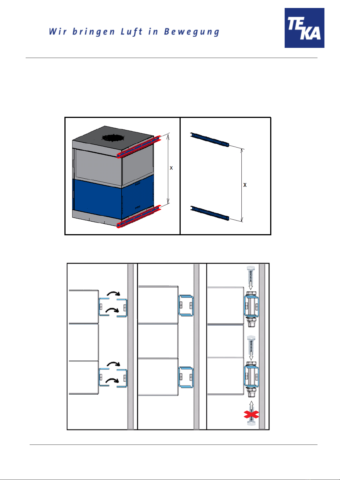
4.1. Mounting height 8
4.2. Mounting of the unit to the wall 9
5. Commissioning 10
5.1. Connecting an extraction element 10
5.2. Electrical connection 11
6. Operating the system 12
6.1. Explanation of the operating elements 12
7. Maintenance 13
7.1. Reset to maintenance state 13
7.2. Replacing the prefilter mat 14
7.3. Replacing the particle filter 15
8. Dismantling / Disposal 16
9. Diagnostics and troubleshooting 17
10. List of spare parts 18
11. Technical data 18
12. EC declaration of conformity 19
13. Training protocol 20
14. Maintenance intervals 21
14.1. Usage-related maintenance 21
14.2. General maintenance 21
14.2.1. Visual inspection of the device 22
14.2.2. Visual inspection of the pipelines for dust deposits 22
14.2.3. Visual inspection of the pneumatic pipes 23
BA_CareMaster-Wand_1-und-2_20230808_EN
2
08.08.2023

1. General
Congratulations on purchasing the product from TEKA.
Our engineers ensure that our devices reflect the state of the art through continuous development.
Nevertheless, misuse or misconduct can endanger your safety. Please observe the following for a
successful use of the device:
Only authorised and instructed personnel can carry out transport, operation,
maintenance and repair of the device. The operator must ensure that the operating
personnel take note of these instructions.
Please read these instructions before operating the device, and observe the safety
precautions to avoid injury!
Store this manual in a safe place! These instructions are to be regarded as a component
of the product!
Adhere to all product notes!
Modifications or conversions that the operator carries out at the device without the
consent of the manufacturer, can lead to new safety hazards or to the loss of warranty
claims.
Observe the manufacturer’s instructions. Contact the manufacturer in case of any
uncertainty:
Tel: +49 2541-84841-0
E-mail: [email protected]
BA_CareMaster-Wand_1-und-2_20230808_EN
3
08.08.2023

2. Description of the system elements
2.1. Illustration of the system elements
Installation example:
Z.Nr. 12471704
Pos.1
Pos.2
Pos.3
Pos.4
Pos.5
Operating panel of the control
Particle filter housing
Fan housing
Particle filter
Prefilter mat (into guide frame)
Pos.6
Pos.7
Pos.8
Suction nozzle (CareMaster 1: 1x,
CareMaster 2: 2x)
Exhaust grille
Wall console
2.2. Functionality of the system
The filter unit serves to suck off and filter polluted air (according to the intended use). First of all, the
coarse particles are separated at the prefilter mat in the filter section of the unit. The subsequent particle
filter cleans even fine smokes and dusts. An automatic filter monitoring indicates when a cleaning or a
replacement of the filters is necessary. The purified air is led back into the working room.
BA_CareMaster-Wand_1-und-2_20230808_EN
4
08.08.2023

2.3. Intended use
The device is intended for commercial use. If the device is made publicly accessible, it must never be
operated unsupervised by authorized personnel, authorized by the operator.
The filter unit is mainly used to extract and filter dust and fumes.
WARNING
Improper use can damage parts and be a danger to life and limb!
The device must not be used for the extraction of oil-laden welding fume, explosive dust
and gases, hybrid mixtures, glowing or burning substances, gases, water, etc. The
device must not be operated in explosive zones.
Dangers arising from fire.
If the sucked medium is combustible fume or dust, the operator must determine
beforehand which fire protection measures are to be taken.
2.4. Residual risk
CAUTION
Danger due to possible hazardous materials in the exhaust air flow.
Because the unit does not monitor the quality of the air in the exhaust air flow, we
recommend that you always guide the exhaust air flow exiting our unit to areas (e.g. to the
outside into the open air) in which there is no danger to any living being. To do this, it is
necessary to fit a suitable exhaust air line at the filter unit.
BA_CareMaster-Wand_1-und-2_20230808_EN
5
08.08.2023

3. Safety instructions
3.1. Definition of the hazard symbols
The device is constructed according to the state of the art and the recognised safety regulations.
Nevertheless, during use threats to life and limb of the user or other persons may arise. The impairment
of the machine or other property are also possible. In these instructions we warn by using corresponding
indications.
WARNING
WARNING
These instructions are made in case of risks that can lead to injury or death.
CAUTION
CAUTION
These instructions are made in case of risks that can lead to injury.
NOTICE
NOTICE
These instructions are made in case of risks that can lead to material damages.
Information notes are no hazard warnings; they call attention to useful information.
3.2. General safety instructions
WARNING
Dangers arising from improper use / unauthorised operations.
The operator must ensure that their authorised personnel are familiar with all the safety
indications in this manual in advance. The operator is responsible for ensuring that all work
is carried out by authorised and qualified personnel. We therefore recommend using the
training protocol on the last page for that purpose (see chapter “Training protocol”).
Laymen are allowed to operate the device after having received the necessary instructions.
But they are not allowed to carry out any installation, repair or maintenance work.
Dangers arising from fire.
In case of fire, if possible, switch the unit immediately off or disconnect it from the power
supply. Fire extinguishing measures which the operator is obliged to determine beforehand
must be initiated immediately.
BA_CareMaster-Wand_1-und-2_20230808_EN
6
08.08.2023

WARNING
Dangers arising from electricity.
The operator must ensure that electrical plants and equipment are only built, modified and
maintained by a qualified electrician or under the direction and supervision of a qualified
electrician. Do not work on components if you are not sure that these are disconnected. If
necessary, disconnect the device from the electric power supply and secure it against
unauthorized restarting.
4. Storage, transport and installation of the device
WARNING
Risk of injury from tilting or unmounted components when stored or transported.
The device must be secured against tilting and slipping when it is stored or transported. Do
not stand under or next to the floating load. Lift trucks, forklift trucks and transport cranes
must have a sufficient minimum load bearing capacity.
Risk of injury arising from the falling unit at its destination.
The unit must be firmly mounted to the destined wall. The wall must be vibration-free and
vertical. The operator must check if the wall provides a sufficient bearing capacity.
NOTICE
Damage or functional impairment of the unit due to climatic influences.
The unit must be stored in a dry place and protected against moisture during transport. As a
matter of principle, the filter unit is not designed to be installed outdoors. In this case contact
the manufacturer in order to find out if a caping or a trace heating system are necessary.
BA_CareMaster-Wand_1-und-2_20230808_EN
7
08.08.2023

4.1. Mounting height
The mounting height of the filter unit depends on the capturing element connected to the filter unit.
device with a suction arm:
device with a wall bracket:
device with an exhaust crane:
BA_CareMaster-Wand_1-und-2_20230808_EN
8
08.08.2023

4.2. Mounting of the unit to the wall
Wall brackets are already attached to the filter unit upon delivery.
● The two other wall brackets must be screwed to the wall. Pay attention to an identical distance
"X".
● Put the filter unit with its wall brackets on the wall brackets attached to the wall and screw them
by means of the delivered screws.
BA_CareMaster-Wand_1-und-2_20230808_EN
9
08.08.2023

5. Commissioning
WARNING
Dangers arising from a defective condition of the unit.
Make sure that the measures described in this chapter are completed before the
commissioning of the unit. All doors of the unit must be closed and all necessary connections
must be attached before turning the unit on. Do not operate the unit if any components are
defective, missing or damaged. Check the orderly condition of the unit before switching it on.
The unit must not be operated without a filter element.
NOTICE
Damaged supply lines.
Make sure that the supply lines are protected against damage by forklift trucks and similar
events. Protect all supply lines from heat, moisture, oil and sharp edges.
5.1. Connecting an extraction element
For extracting the contaminated air - according to the intended use - the provided extraction element
(e.g. suction arm, suction hose, ...) must be connected at the suction nozzle (see chapter 2.1).
The assembly of a suction arm is described in the separate operating manual.
When using a detection element with extraction hood, the extraction hood must track the welding seam,
possibly taking advantage of the thermally induced welding fume movements.
: However, it is important to ensure that connections between the workpiece and
the extractor hood (and generally between the workpiece and filter device) are avoided, so that,
if necessary, the welding current cannot flow back through the protective conductor of the filter
device to the welding machine.
BA_CareMaster-Wand_1-und-2_20230808_EN
10
08.08.2023

5.2. Electrical connection
WARNING
Risk of electric shock.
Electrical plants and equipment may only be built, modified and maintained by a qualified
electrician or under the direction and supervision of a qualified electrician. Do not work on
live electrical components and elements if you are not sure that these are indeed
disconnected. If necessary, disconnect the device from the mains. The operator is
responsible for a potential-free balance of the equipment.
If the unit is equipped with a frequency converter, then it may only be operated on networks
with an AC/DC sensitive RCCB. For frequency converter operation, the cross section of the
protective conductor
● must be at least 10mm²,
● and must be at least equal to the size of the operator side outer conductor
cross-section.
NOTICE
Electric malfunction possible in cause of an incorrect power supply.
Pay attention to the admissible supply voltage. Please observe the specifications on the type
plate.
● Mount the housing of the external control (if it is not mounted on the device itself) close to the
device on the wall or at any other appropriate mounting point. Or mount the control together
with a cabinet console on a suitable surface, for example using lag bolts or heavy-duty anchors.
: The housing is not suited for outdoor installation.
● Connect all visible cables and hoses are according to their functions. When delivered they are
labelled according to their functions. When connecting to the control, please observe the
specifications on the circuit diagram which is attached to the control.
● Connect the unit to the power supply.
● Check if the direction of fan rotation is correct (This is not necessary in the case of units with a
frequency converter). A wrong rotation direction can be identified thanks to the sticker sticked to
the fan scroll which is showing the direction. Compare the rotation direction on the sticker to the
rotation direction of the motor cooling fan when the motor is running down after being switched
off. If the motor rotates in the wrong direction, disconnect the device from the power supply and
exchange two phases at the supply line to the control.
: When the fan rotates in the wrong direction, the extraction capacity is
reduced.
BA_CareMaster-Wand_1-und-2_20230808_EN
11
08.08.2023

6. Operating the system
6.1. Explanation of the operating elements
Operating elements for the device control
Representa
tion
Designation
Description / function
ON-OFF-switch
By means of this switch, the device is switched on and off.
When the device is switched off, it is not disconnected from
the power supply.
Operating elements for status and error messages
Representa
tion
Designation
Description / function
Signal lamp “red”
Flashing up means that the air-flow rate of the device is not
sufficient anymore. Filter elements must be cleaned or replaced.
When using extraction elements with a suction hood, it is possible
that the throttle valve(s) in the suction hood are closed. In this
case open the throttle valves.
Indicator lamp “green”
Flashing up means that the device is in operation.
Operating hour counter
The number of operation hours during which the device was in
operation is shown.
BA_CareMaster-Wand_1-und-2_20230808_EN
12
08.08.2023

7. Maintenance
In accordance with national regulations, the operator is obliged to carry out repeat and functional tests.
Unless otherwise specified by national regulations, we recommend regular visual inspections and
functional tests of the device as described in the chapter “Maintenance intervals”.
You find the chapter “Maintenance intervals” at the end of the document. The general
maintenance (visual inspection, etc.) is also explained there.
In the chapter “Maintenance intervals” there is information on the maintenance intervals of the filter
elements. But these are only recommendations. Depending on the application (multi-shift operation,
dust generation, ...) it may be necessary for the operator to change the maintenance intervals.
In this chapter the maintenance work which is caused by wear caused during operation is described.
WARNING
Work on the open system entails the risk of electrical shock or accidental restart the
system. Both pose a danger to life and limb.
When cleaning and servicing equipment during the replacement of parts or when changing
to another function, set the device to maintenance condition first (see chapter “Reset to
maintenance state”).
A recommissioning of the device must only occur if it is ensured that the device is
functionally equivalent to the original state.
CAUTION
Hazards to the respiratory tracts are possible.
All maintenance work must only be carried out in well-ventilated rooms and while wearing an
appropriate respiratory mask! We recommend: respiratory protection half mask DIN EN
141/143 protection level P3. For all maintenance work ensure a cautious handling of filter
elements and components in order to avoid whirling up dust.
The operator is obliged to store and dispose of the collected dust in accordance with national or
regional regulations. For all maintenance or cleaning work please refer to the applying
environmental regulations. Pollutants and filter elements must be disposed of or stored according
to the regulations as well. If you have any doubts, we recommend contacting a disposal
contractor in your area.
7.1. Reset to maintenance state
● Switch off the unit. Secure the unit against unauthorized restarting during maintenance.
When the device is switched off, it is not disconnected from the power
supply.
● After completion of all maintenance work the unit can be switched on again.
BA_CareMaster-Wand_1-und-2_20230808_EN
13
08.08.2023

7.2. Replacing the prefilter mat
The prefilter mat is installed upstream to the particle filter and separates the coarse particles. This
extends the service life of the particle filter.
The prefilter mat must be changed after a certain number of operating hours. The time depends on the
amount of accumulated dust, and therefore cannot be determined beforehand. At the latest, the prefilter
mat must be changed when changing the particle filter.
CAUTION
Whirling up dust is possible.
The prefilter mat is a disposable filter element. Do not try to clean the filter element.
● Open the service door of the particle filter housing (see chapter 2.1).
● Lower the lifting device (A) by turning the clamping screw (B). Therefore, use the hexagon key
that is located on the right of the clamping screw.
● Carefully pull the entire filter pack, incl. the insert frame (see chapter 2.1) out of the housing.
● Remove the prefilter mat from the insert frame and dispose of or store it according to the
regulations.
● Put a new prefilter mat into the insert frame.
: Only use TEKA spare filters. Otherwise the proper functioning of the unit is
not guaranteed.
● Push the filter pack back into the dust collecting housing as far as it will go.
● Elevate the lifting device by turning the clamping screw so that the upper filter element is
pressed tightly against the above housing.
● Close the service door.
BA_CareMaster-Wand_1-und-2_20230808_EN
14
08.08.2023

7.3. Replacing the particle filter
Replacing the particle filter is necessary when the device control signals the corresponding error. (see
chapter "Description of the control elements")
CAUTION
Whirling up dust is possible.
The particle filter is a disposable filter element. Do not try to clean the filter element.
When replacing the particle filter, the prefilter mat must be replaced as well.
● Open the service door of the particle filter housing (see chapter 2.1).
● Lower the lifting device (A) by turning the clamping screw (B). Therefore, use the hexagon key
that is located on the right of the clamping screw.
● Carefully pull the particle filter (see chapter 2.1) out of the housing.
● Push the new particle filter back into the particle filter housing as far as it will go.
: Only use TEKA spare filters. Otherwise the proper functioning of the unit is
not guaranteed.
● Elevate the lifting device by turning the clamping screw so that the particle filter is pressed
tightly against the above housing.
● Close the service door.
BA_CareMaster-Wand_1-und-2_20230808_EN
15
08.08.2023

8. Dismantling / Disposal
Only authorised personnel may disassemble the machine.
WARNING
Dangers arising from electricity.
Before the dismantling of the machine it has to be disconnected from the power supply and
all supply lines.
CAUTION
Whirling up dust is possible due to the deposited dust.
During all work a suitable respiratory protection and protective clothing have to be worn.
The operator is obliged to store and dispose of the collected dust in accordance with national or
regional regulations.
BA_CareMaster-Wand_1-und-2_20230808_EN
16
08.08.2023

9. Diagnostics and troubleshooting
A list of possible system errors is provided in the table.
Faults indicated by control elements are explained in the chapter “Description of the control
elements”.
A recommissioning of the device must only occur if it is ensured that the system is functionally
equivalent to the original state. Repairs may only be carried out by TEKA personnel or, after
consultation with TEKA GmbH, by the personnel authorised by the operator.
Adhere to the instructions in the chapter "Safety instructions" and " Maintenance" when carrying out any
repairs. If in doubt, contact our TEKA service department:
Tel: +49 2541-84841-0
E-mail: [email protected]
Fault
Cause
Removal
System does not start.
Plug power supply is missing or
incorrectly inserted.
Plug connector check power
supply / plug in correctly.
No power at outlet.
Check the mains, remove error if
possible.
Dust at the service door
of the filter housing.
The door is not correctly closed.
Close the door.
The seal between the service door and
filter housing is damaged.
The seal must be replaced.
Escape of dust at the hinge.
The hinge must be reoriented or
replaced.
Suction power too low
(smoke hardly
extracted).
Filter element is saturated.
Replace the filter package,
dispose of old filter properly!
Damage at the extraction elements.
Replace the extraction elements.
The motor rotates in the wrong
direction.
The rotating field of mains
connection point must be
changed.
Suction line contracted.
Check and fix.
Exhaust line contracted.
Check and fix.
The system is very noisy.
The motor rotates in the wrong
direction.
The rotating field of mains
connection point must be
changed.
The unit is untight.
Check and fix.
BA_CareMaster-Wand_1-und-2_20230808_EN
17
08.08.2023

10. List of spare parts
Filter element
Article no.
Prefilter mat “M5” (10 pieces / 610 x 610 x 20 mm)
10032
Particle filter “H13” (610 x 610 x 292+6)
10030
Particle filter “F9” (610 x 610 x 292+6)
10029
11. Technical data
Version
CareMaster Wand - 1
CareMaster Wand - 2
Supply voltage
V
230 / 400 / 500
230 / 400 / 500
Frequency
Hz
50
50
Type of current
Ph
1 / 3 / 3
1 / 3 / 3
Engine power
kW
1,5
2,2
Air flow volume max.
m³/h
1800
3500
Negative pressure max.
Pa
3000
2500
Protection class
IP54
ISO class
F
Extraction performance
%
> 99
Width
Depth
Height
mm
mm
mm
665
681
930
665
681
930
Weight
kg
129
142
Sound pressure level
dB(A)
72
74
Allowed ambient temperature
°C
+5 to +35 (during operations)
-10 to +40 (during transport and storage)
Max. temperature of polluted air at
the capture point
°C
+50
Allowed max. humidity
%
70
BA_CareMaster-Wand_1-und-2_20230808_EN
18
08.08.2023

12. EC declaration of conformity
according to the Machinery Directive 2006/42/EG, Annex II, 1 A
TEKA Absaug- und Entsorgungstechnologie GmbH
Millenkamp 9, D-48653 Coesfeld
Designation of the device: CareMaster Wall 1 / CareMaster Wall 2
We hereby declare under our sole responsibility that the product mentioned above, from the serial
number A22600010011001 resp. P57300010011001 on, conforms to the following directives:
Machinery Directive: 2006/42/EG
Electromagnetic Compatibility: 2014/30/EU
RoHS directive: 2011/65/EU
This declaration will become void if the device is exposed to modifications that are not approved by the
manufacturer in written form.
Authorized representative for the technical documentation:
TEKA Absaug- und Entsorgungstechnologie GmbH, Millenkamp 9, D-48653 Coesfeld
(Jürgen Kemper, managing director)
Coesfeld, 3rd january 2023
BA_CareMaster-Wand_1-und-2_20230808_EN
19
08.08.2023

13. Training protocol
Designation of the device: CareMaster Wall 1 / CareMaster Wall 2
(This form can be used by the operator to document the training of the employees. Training should be performed by
authorized personnel only. Refer to the instructions in Chapter "Safety Instructions")
By his signature, the employee confirms that he has been instructed regarding the following items:
Instruction
completed
Description of the device
Operation and application of the device
Explanation of the safety instructions
Behavior in case of fire
Explanation of the operation elements
Change and dedusting of the filter elements
Appropriate disposal
Maintenance works / Maintenance intervals
Name of the employee (legible)
Signature
Introduction through (legible):
Signature:
BA_CareMaster-Wand_1-und-2_20230808_EN
20
08.08.2023
This manual suits for next models
1
Table of contents
Other Teka Water Filtration System manuals
Popular Water Filtration System manuals by other brands

HYDAC FILTER SYSTEMS
HYDAC FILTER SYSTEMS OLF-5 Series Installation and maintenance instructions

Sea Recovery
Sea Recovery Aqua Matic XL Series owner's manual

Wellness
Wellness Wellness Shower Usage & Care Guide

US Water Systems
US Water Systems Fusion Oxi-Gen 089-FSF OG Series Installation, operation and maintenance manual

TCi
TCi MFC A installation instructions

SpectraPure
SpectraPure MAXCAP RO Installation and operating manual