FLEET Kombi Classic User manual

User Manual
Fleet (Line Markers) Limited, Fleet House,
Spring Lane, Malvern, Worcestershire,
WR14 1AT
Tel: 01684 573535
sales@flmuk.com
www.fleetlinemarkers.co.uk

Introduction
INTRODUCTION
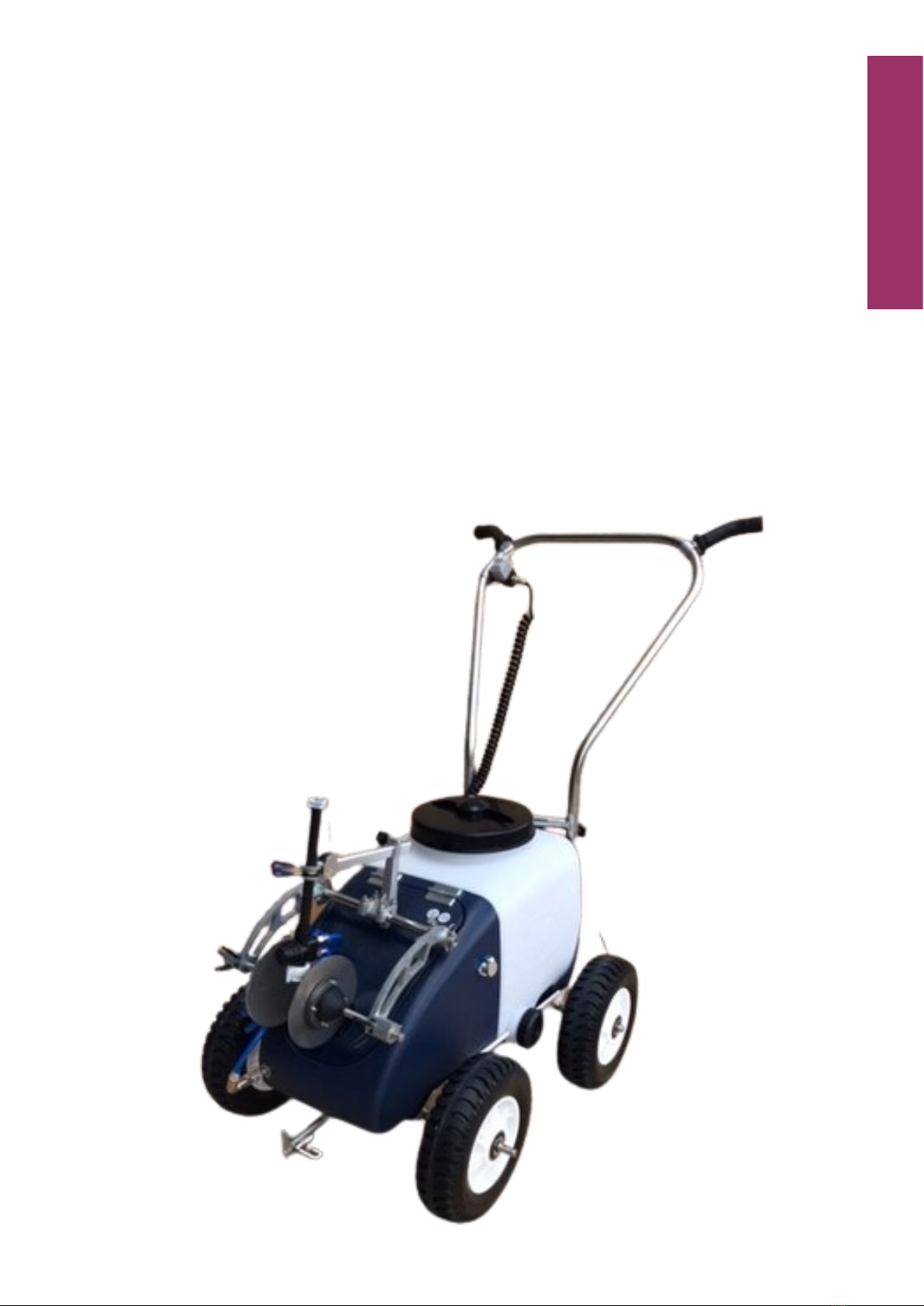
Thank you for choosing the Kombi Classic Line Marker from Fleet (Line
Markers) Limited. Founded in the 1950’s Fleet are regarded as the
world’s leading expert in the field of line marking.
Of course its not just the machines that Fleet are famous for, our range
of line marking paints are used around the world, wherever the pitch,
whatever the occasion.
Form more details on any of the products in Fleet’s range please visit
www.fleetlinemarkers.co.uk.
CONTENTS
Assembly
Operation
Maintenance
Storage
Troubleshooting
Parts List
Warranty
1
ASSEMBLING YOUR KOMBI CLASSIC MARKER
PREPARING FOR USE
1. Carefully remove the machine and accessories from packaging.
2. Insert handlebar section; adjust to suit user’s height and tighten us-
ing thumb screws.
3. Bar ends can be adjusted to suit hand position using the supplied
5mm allen key.
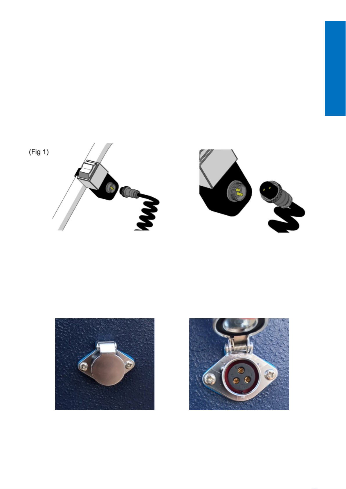
4. Connect switch using the coiled power cable. (Fig 1)
5. Position machine near a 230/240V AC power supply, connect
charger to charge socket and switch on. (Fig 2)
CAUTION. Only use the supplied charger. Use of other equipment
may cause fire or damage the battery. Maintain battery charge at all
times, charge once a month if stored for long periods without use.
(Fig 2)
6. When charging, the LED on the charger illuminates red. When the
battery is fully charged, the LED illuminates green.
Assembly
2
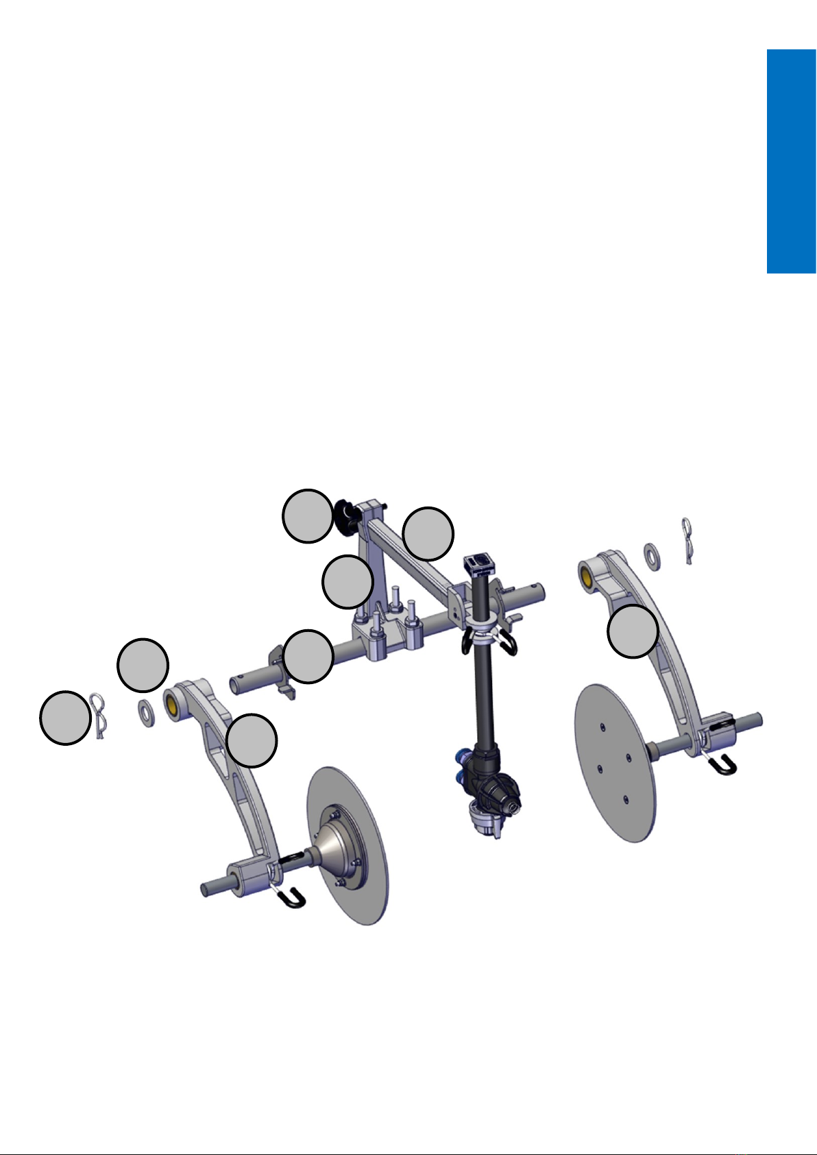
KNIB AND NOZZLE ASSEMBLY
The Knib and nozzle assembly is located inside the paint tank of the ma-
chine and requires some assembly before use.
Refer to the diagram below and follow these steps.
1. Remove packaging from tank.
2. Place arms (A) & (B) over the pivot bar (C)
3. Fit a washer (D) on each end of the pivot bar shaft, secure using R
Clip (E)
4. Insert nozzle support arm (F) into the support pillar (G) and secure
with thumb screw (H).
H
G
F
B
C
D
E
A
Assembly
3
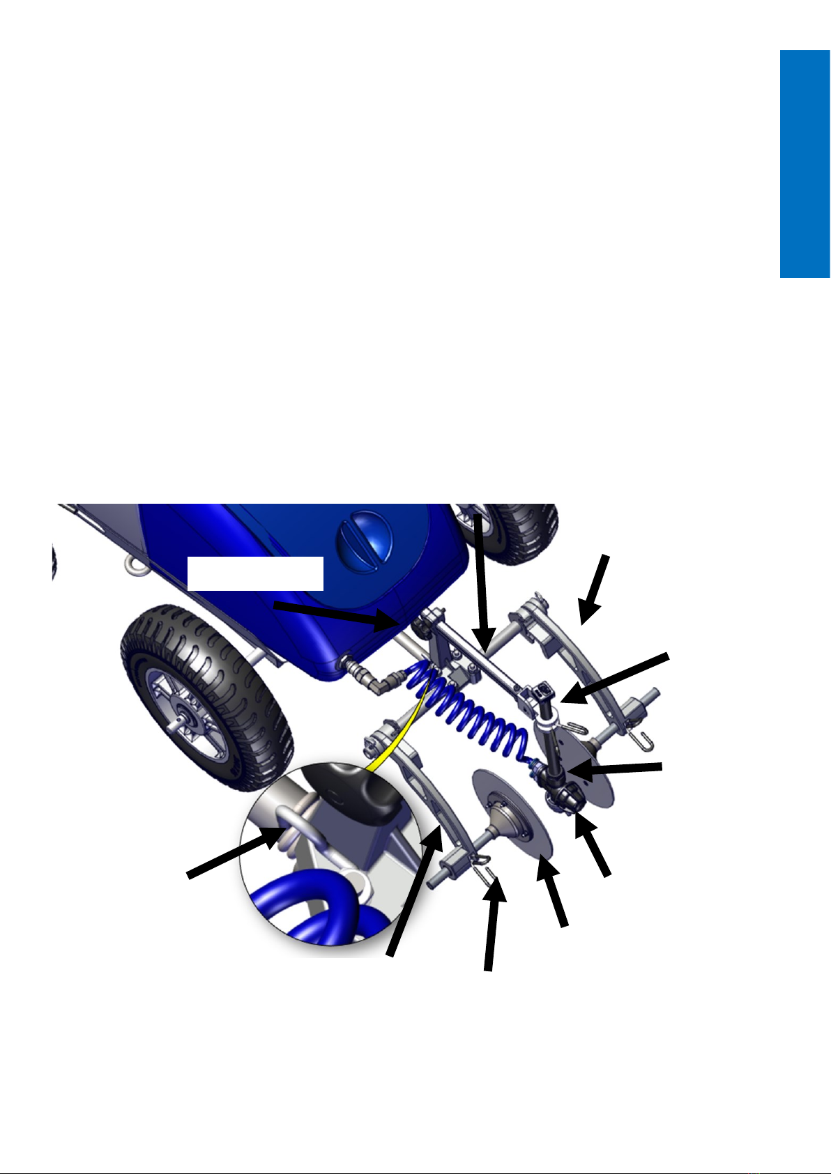
The knib and nozzle assembly can be fitted to the central post at the
front of the machine or to either side of the front axle.
Front mounted knib and nozzle assembly
1. Fit the knib and nozzle assembly onto the tapered stem at the front
of the machine.
2. Compress knib retainer clip and position the arm on the flat of the
support pillar.
3. Hinge the nozzle assembly to the vertical position.
4. Ensure that the nozzle is centered between the line forming disks,
adjust if necessary using the thumb screw.
5. Connect blue coiled hose to the front bulkhead connector.
(Fig 4) Knib and nozzle assembly mounted on the front of the machine.
Thumb Screw
Nozzle Support As-
sembly
Wheeled Knib
Nozzle Height Adjustment
Spring Collar
Nozzle Assembly
Tip Assembly
Line Forming Disc
Spring Collar
Guide Arm
Knib Retainer
Assembly
4

Side Mounting your Knib
1. Remove the R clip from the required side of the knib. (Fig 5)
2. Fit the pivot bar of the knib over the axle and align the holes. Refit
the R clup to secure the knib to the axle.
3. Hinge the nozzle post to the vertical position and ensure that the
nozzle is centered between the line forming discs . Adjust if
necessary.
Note: Further adjustment of the nozzle
position can be achieved by adjusting
the U bolts.
4. Arrange the blue coiled hose away
from the wheel and connect to the
bulkhead fitting (Fig 6)
Note: Knib can be fitted in either trailing (Fig 7) or forward facing
position. (Fig 8)
(Fig 5)
(Fig 6)
(Fig 7) (Fig 8)
Assembly
5
OPERATING YOUR KOMBI CLASSIC LINE MARKER
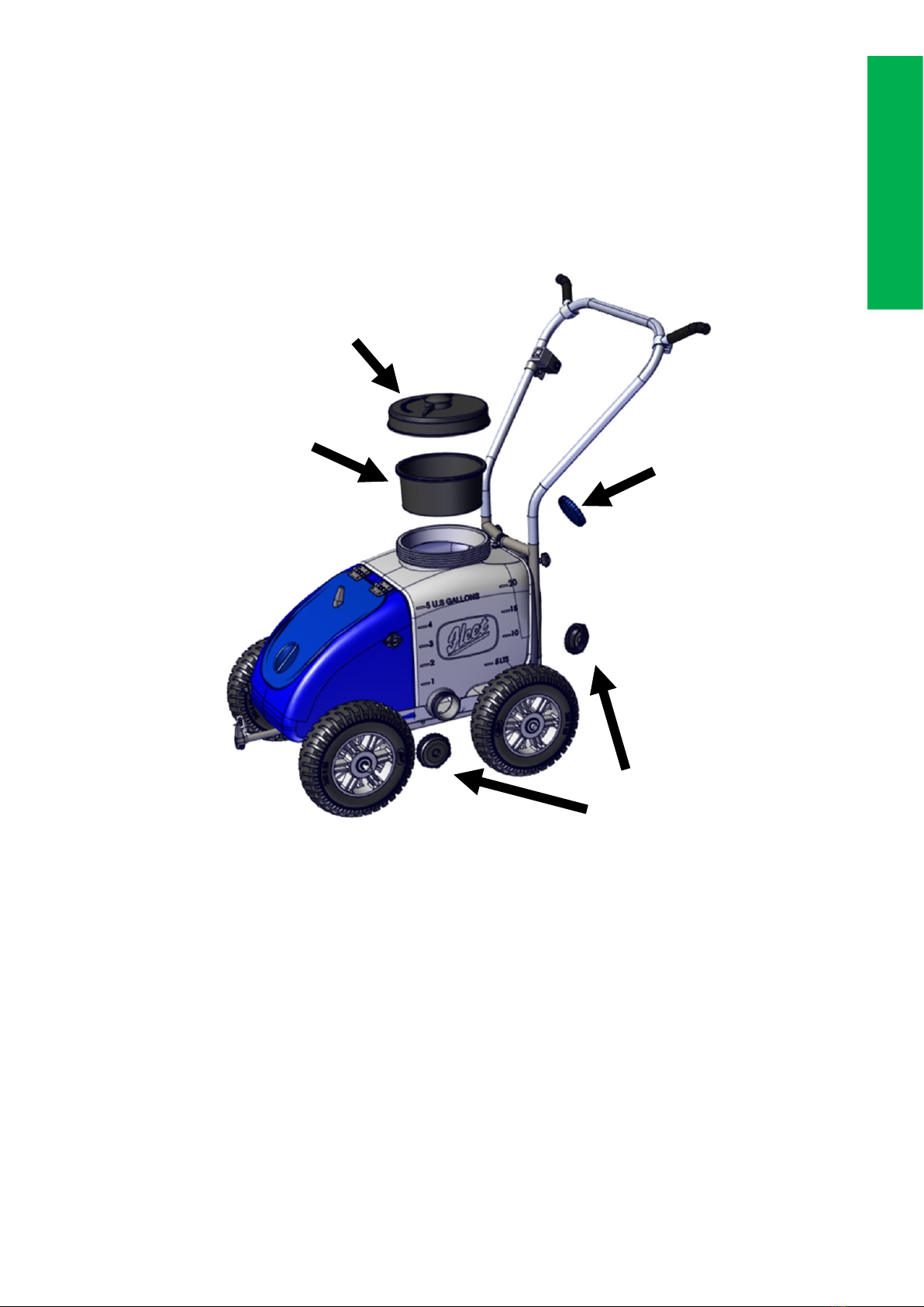
Filling the water tank
1. Remove the filler cap from the rear of the machine.
2. Fill the water tank with clean water, ensure no debris enters the tank
and replace cap (Fig 10)
Filling the paint tank
Place the basket filter into the neck of the paint tank. ALWAYS use the
basket filter to eliminate debris from entering the tank.
Concentrated paints
A. Fill the paint tank with water to correct dilution rate, tank markings
are provided as a guide.
B. Fill the paint tank with the selected Fleet paint and refit the lid.
Note: always pour water in first followed by Fleet paint.
Ready to use paints
A. Pour Fleet ready to use paint into the paint tank.
(Fig 10) Tank lid
Basket Filter Filler Cap
Drain Caps
Operation
6
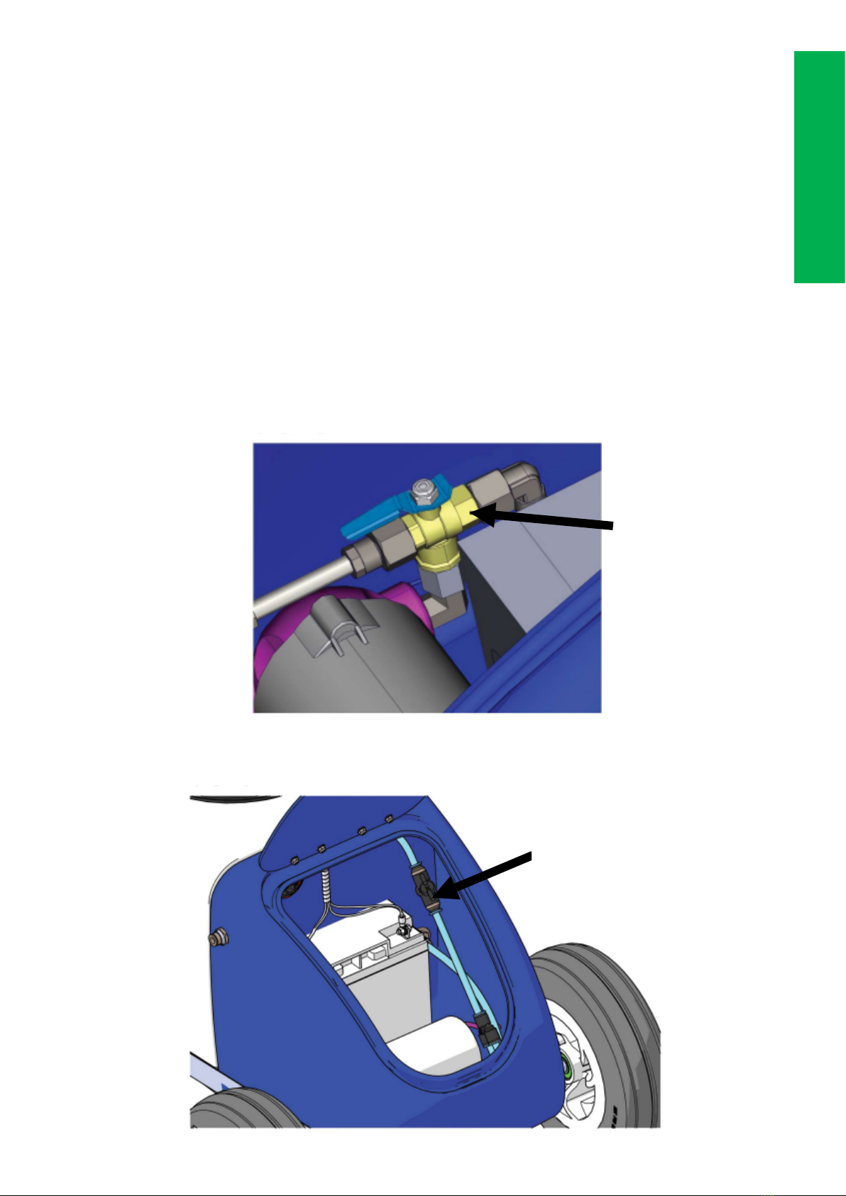
Flow return tap
The Kombi Classic line marker is fitted with a flow return tap, this can be
used for mixing concentrates and bleeding air from the system.
To operate the flow return system, proceed as follows:
1. Ensure the paint/water changeover valve is in the ‘paint’ position
(lever pointing forward) (Fig 11)
2. Turn the flow return tap through 90 degrees (in line with hose. See
Fig 12)
3. Switch the machine on by switching the ON/OFF switch, paint will
now circulate around the system and back into the tank.
(Fig 11)
(Fig 12)
Paint/water tap
Flow Return Tap
Operation
7

Setting the line width
The line width is determined by the width between the guide discs and
the nozzle height. Both must be adjusted correctly to obtain a good line
with the optimum paint usage. A ruler is located in the nozzle post for
measuring the line width and the nozzle height.
1. With the line forming discs resting on the ground, compress the
spring collars and slide the line forming discs in or out to achieve the
desired line width.
IMPORTANT: Both the line forming discs must be adjusted so that
the nozzle is central between them.
Setting the nozzle height
1. Hinge the nozzle post to the vertical position. Adjust the nozzle
height by squeezing the spring collar and sliding the nozzle post up
or down for the desired line width. A ruler is provided in the nozzle
post.
2. A reference guide is located underneath the bonnet and give approx-
imate nozzle height for a range of line widths. NOTE: this is only in-
tended as a guide. The operator must observe the spray pattern and
adjust the nozzle height to form a good line for the local conditions
(Fig 13)
Nozzle post
Spring Collar
Line forming disc
Ruler
Operation
8
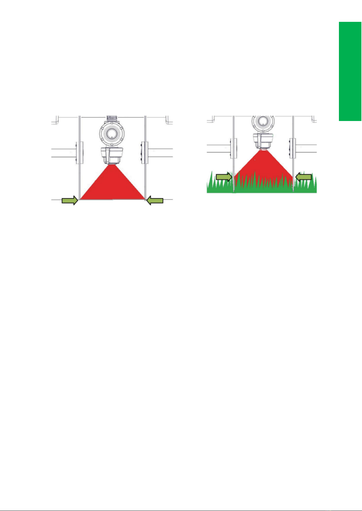
3. On an area of the ground away from the pitch, briefly switch on the
pump. Observe the spray pattern, check that the spray fan just
reaches the line forming discs at the top of the grass height. For hard
surfaces the spray fan should just reach the line forming disc at the
ground surface. If necessary adjust the nozzle height. Turn off the
pump
4. Close the bonnet. Ensure the blue coiled hose is arranged with no
kinks and is not fouling on the guide discs. The Kombi Classic line
marker is now ready for line marking.
(Fig 14)
Operation
9
LINE MARKING WITH YOUR KOMBI CLASSIC LINE MARKER
Marking a line
1. Ensure there is correctly mixed product in the paint tank.
2. Ensure the battery is fully charged
3. Paint/water valve is in the ‘paint’ position (lever pointing forward)
4. Ensure the flow return tap is in the OFF position (tap lever at 90 de-
grees to the hose)
5. Switch the pump ON and immediately start walking at a steady
speed along the guide line. The guide line could be a previously
marked line, string or chalk line.
6. At the end of the line switch the pump OFF and stop walking.
7. Lift the line forming discs from the surface and position the machine
at the start of the next line.
8. If there is to be a break in marking always flush the nozzle with water
using the Paint/water change over tap. Briefly flush the nozzle into a
container or on waste ground away from the pitch area. Refer to
page 12.
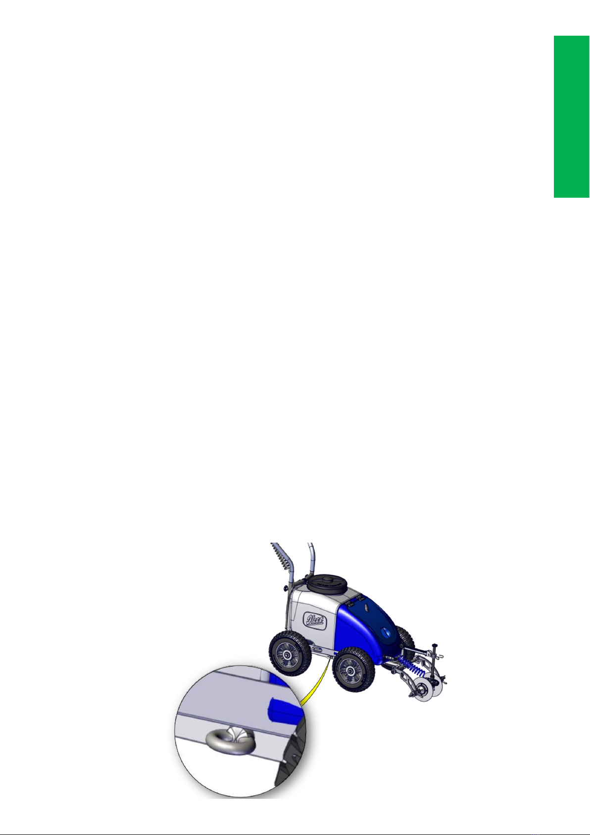
Marking Circles
An eyelet is located on the chassis (left hand side) to aid marking circles.
This can be used with a string or chain line located off a central point al-
lowing the machine to maneuver in a uniform circle (Fig 16).
Operation
10
FLUSHING AND CLEANING
IMPORTANT: When cleaning./flushing the Kombi Classic line marker, ensure
that water courses are not contaminated with paint. If in doubt, check with the local
authority.
Quick flush (daily)
This can be used before breaks in operation or at the end of a line marking day.
1. Ensure that the water tank has sufficient water for the cleaning operation.
2. Position the machine where the contents of the pipework can be flushed and
cleaned.
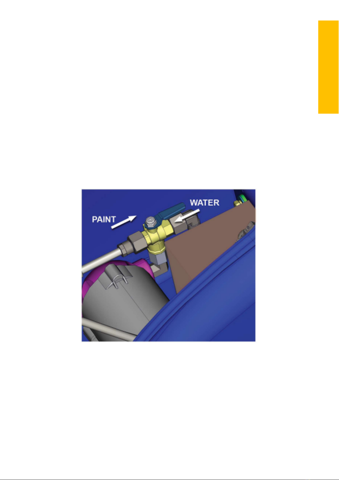
3. With the paint/water tap in the ‘water’ position (Fig 17), turn on the pump. Allow
the water to spray through the nozzle, when clear water is observed turn off
the pump.
.
(Fig 17)
Maintenance
11

Full System flush (weekly)
It is not recommended to store paint in the machine for longer than 24hrs
1. Ensure that the water tank has sufficient water for the cleaning operation.
2. Position the machine where it can be flushed and cleaned.
3. With the paint/water tap in the ‘water’ position (Fig 17), and the flow return tap
inline with the pipe, turn on the pump. Allow water to circulate into paint tank,
when running clear, turn off pump.
4. The contents of the paint tank can be emptied into a suitable sealed container.
Remove drain cap and tilt machine to empty.
5. Paint tank should be cleaned to remove any excess paint from the bottom and
sides.
6. Replace drain cap and fill with 5 litres of clean water and optional Kombi
Klean.
7. Position the nozzle assembly over a drain or suitable container.
8. With the paint/water change over tap in the ‘paint’ position (Fig 17), turn on the
pump. Allow the water to spray through the nozzle until the paint tank is empty.
9. Remove the bayonet cap complete with the nozzle tip and filter. If necessary,
rinse to clean.
10. Refit the bayonet cap complete with the nozzle tip and filter
11. Using a damp cloth lean any paint overspray from the following:
A. Line forming discs and guide shafts. Build up of paint on the guide
shafts will make line width adjustment more difficult
B. Generally clean and remove paint overspray or spills from the machine
Maintenance
12

MAINTENANCE ACCESSORIES
These accessories are available from the Fleet Line Markers online
store. Visit www.fleetlinemarkers.co.uk for more details.
Fleet Ultrasonic Cleaner
Manufactured to use with all Fleet nozzle tip line marking machines, the
ultrasonic Nozzle Tip Cleaner works through the cavitation effect caused
by high frequency ultrasonic wave vibrations in the fluid, providing an
effective solution for the removal of paint, dirt and grime which would
normally require tedious manual cleaning by hand.
The cleaner can be used with a wide variety of Fleet machine parts
including nozzles, filters, pipework and couplings, returning them to an
almost new condition without any damage.
Fleet Kombi Klean
Manufactured to use with all Fleet machines. The Kombi Kleean helps to
flush through the pump and pipework the clean then of paint after us of
the machine. Suitable for use on the machine inside and out.
Maintenance
13
STOWING THE KOMBI CLASSIC LINE MARKER
When the machine has been flushed and cleaned, prepare the Kombi
Classic line marker for transport or storage as follows:
1. Squeeze nozzle height adjustment spring collar and slide the nozzle
post down to the minimum height.
2. Using the spring collars, slide the line guide discs in, so that they
support the nozzle assembly centrally.
3. Loosen knib retainer clip and lift the knib from the tapered post.
4. Park the knib onto the bonnet horn.
5. The Kombi Classic line marker is now ready for transportation and/or
storage.
Storage
14

TROUBLESHOOTING
If the Kombi Classic line marker is not producing the perfect line, the
table below is to help diagnose and remedy simple issues. The main
cause for failure is inadequate cleaning/flushing. It is imperative to keep
the paint system free from dried paint particles.
Note: These procedures presume that there is sufficient Fleet paint
in the paint tank.
No. Issue Cause Remedy
1Intermittent line
Airlock in paint sys-
tem
Bleed paint system
as follows: Refer to
page 8.
2Line Striping Nozzle tip contami-
nated
A. Remove nozzle
and clean in
sonic bath.
B. Replace with
new nozzle
3Low pump pressure Low battery charge Recharge battery
4No machine power Low battery charge Recharge battery
Troubleshooting
15

Quick Connectors
Removal
1. To release a pipe from a quick connector, push on both sides of the
blue collar.
2. With the collar oushed in, pull the pipe from the connector.
Replacement
1. To replace a pipe into a quick connector, simply push in the pipe.
The pipe should be inserted 15mm to ensure a good connection.
Compression fittings
Removal
1. To release a pipe from a compression fitting use a 12mm, 13mm or
14mm spanner (dependent on fitting) to loosen the end cap.
2. Pipe can be pulled out.
3. The use of two spanners maybe required if the compression fitting is
to be replaced.
Troubleshooting
16
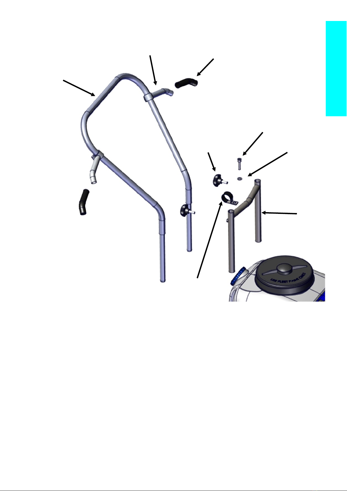
Diagrams
PART NO PART NAME
KOMBCOMP1028 Handle Bar Top Section
KOMBCOMP1029 Handle Bar Bottom Section
KOMBCOMP1106 Steel P Clip 22mm
KOMBCONS1003 M6 x 25 Socket Cap Head Screw
UNIVCOMP9009 M6 Thumb Screw
UNIVCOMP9013 Rubber Handle Grips
UNIVCOMP9038 Bar Ends (Pair)
UNIVCONS9058 M6 x 20 Flat Repair Washer
KOMBCOMP1028
KOMBCOMP1029
KOMBCOMP1106
KOMBCONS1003
UNIVCOMP9009
UNIVCOMP9013
UNIVCOMP9038
UNIVCONS9058
Parts List
17

PART NO PART NAME
UNIVCOMP5555 Wheel & Solid foam tyre
KI00COMP5058 Bonnet Hinge (Sprung)
KICOCOMP6017 Bonnet Horn
KOMBCOMP1233 Tapered Stem
KOMBCOMP1026 Tank Lid
KOMCOMP1027 Tank Filter
KOMCOMP1033 Bonnet
KOMBCOMP1036 Plastic Drain Cap
KOMBCOMP1037 2 Inch vented water cap
KOMBCONS1017 15mm Retaining Clip for Knib
UNIVCONS9058 M6 x 20 Flat Repair Washer
UNIVCONS9113 M6 x 12 Socket Cap Head Screw
KOMBCOMP1026
KOMBCOMP1027
KI00COMP5058
KICOCOMP6017
KOMBCOMP1033
KOMBCOMP1233
KOMBCONS1017
UNIVCOMP5555
KOMBCOMP1036
KOMBCOMP1037
Parts List
18

PART NO PART NAME
KI00COMP5071 Y Shaped Connector 8mm
UNIVCOMP8521 Bowl Filter Complete
KI00COMP5098 Push Fit Hand Valve
KOMBCOMP1046 1/4 BSP Male Thread Female Coupler
KOMBCOMP1031 Tank Filter
UNIVCOMP8522 8mm x 6mm P/Mount Quick Release Bulkhead
UNIVCOMP1055 1/4 BSPT M—1/4 BSP F Brass
UNIVCOMP9005 Clear PVC Hose
UNIVCOMP9056 Quick Release Compression fit Bulkhead
UNIVCOMP9112 3/8 Elbow Connector
UNIVCOMP9113 1/4 Male/ Male Elbow
UNIVCOMP9115 Female Pipe Elbow
UNIVCONS9086 6mm Male Bullet Red Terminal Connector (Not illustrated)
UNIVCONS9087 6mm Female Red Receptacle Terminal Connector (Not illustrated)
FASTCOMP2096 Fuse Holder
UNIVCOMP9214 7.5 amp Blade Fuse
KOMBCOMP1031
KIC00COMP5098
UNIVCOMP9005
KI00COMP5071
KOMBCOMP1046
UNIVCOMP9112
UNIVCOMP9114
UNIVCOMP9056
UNIVCOMP8521
UNIVCOMP9115
KOMBCOMP1041
UNIVCOMP1055
UNIVCOMP9113
Parts List
19
Other FLEET Industrial Equipment manuals


