FLETCHER Alfamacchine U300 User manual

EN INSTRUCTIONS MANUAL
PLEASE RETAIN FOR FUTURE REFERENCE
Name
Function
Model / Type
Serial number
Year of construction
Manual Revision
FRAME ASSEMBLING MACHINE
ASSEMBLY OF FRAMES BY INSERTION OF METAL V-NAILS
U300 (previous version MINIGRAF 3)
01

2TRANSLATION OF THE ORIGINAL INSTRUCTIONS (Keep for future reference)
Document Code Rev. Date saved Date printed
U300 INSTRUCTIONS 01 09/02/2016 09/02/2016
EN
Alfamacchine S.r.l.
Via Selva 23/25
47122 Forlì - Italy
CE DECLARATION OF CONFORMITY
CE CONFORMITY DECLARATION
Il Fabbricante / the Manufacturer Alfamacchine S.r.l.
con sede legale in / Address Via Selva, 23/25 47122 Forlì - Italy
DICHIARA, / Hereby DECLARES,
sotto la propria responsabilità, under its sole responsibility,
declares that the machine: that the machine:
Denominazione / Product Name : FRAME ASSEMBLING MACHINE
Funzione / Purpose : ASSEMBLY OF WOODEN AND SYNTHETIC MDF MOULDINGS USING METAL
V-NAILS
Modello/ Model Name : U300
Tipo / Type : PNEUMATIC
Numero di Serie / Serial Number :
E’ CONFORME ALLE DISPOSIZIONI PREVISTE DALLE DIRETTIVE:
COMPLIES WITH THE FOLLOWING STANDARDS AND DIRECTIVES:
- 2006/42/CE, Direttiva Macchine / Machinery Directive
poiché rispetta tutti i requisiti essenziali di sicurezza e sanitari che le concernono.
because it complies with all the relative essential safety requirements
Technical File drawn up by: ALFAMACCHINE S.R.L.
Technical File drawn up by: ALFAMACCHINE S.R.L.
Forlì ,
___________________________________
Data / Issued Date : Firma il Legale rappresentante / Signature of representative

1
TRANSLATION OF THE ORIGINAL INSTRUCTIONS (Keep for future reference)
Document Code Rev. Date saved Date printed
U300 INSTRUCTIONS 01 09/02/2016 09/02/2016 EN
TRANSLATION OF THE ORIGINAL INSTRUCTIONS
INDEX
EN
1. INTRODUCTION TO USE ......................................................................................................................................................... 2
1.1. HOW TO CONSULT THIS MANUAL AND THE SYMBOLS ADOPTED ....................................................................... 2
.................................................................................................... 2
1.3. TYPE OF USE AND CONTRAINDICATIONS............................................................................................................... 2
1.4. TECHNICAL FEATURES.............................................................................................................................................. 6
1.5. PRODUCTS PROCESSED - HANDLED OR GENERATED ........................................................................................ 7
1.6. EMISSION OF AIRBORNE NOISE............................................................................................................................... 8
1.7. RESIDUAL RISKS - GENERAL INFORMATION .......................................................................................................... 8
1.8. RESIDUAL RISKS ........................................................................................................................................................ 8
1.9. DESCRIPTION OF SAFETY FUNCTIONS................................................................................................................... 9
1.10. DESCRIPTION OF THE MACHINE.............................................................................................................................11
1.11. MAIN MACHINE COMPONENTS .................................................................................................................................11
2. INSTALLATION ....................................................................................................................................................................... 16
2.1. STORAGE................................................................................................................................................................... 16
2.2. CHECKS ON RECEPTION......................................................................................................................................... 16
2.3. TRANSPORT, LIFTING AND HANDLING................................................................................................................... 17
2.4. LIFTING AND HANDLING .......................................................................................................................................... 17
2.4. LIFTING AND HANDLING .......................................................................................................................................... 17
2.5. REMOVING THE PACKAGING .................................................................................................................................. 18
3. PRELIMINARY PREPARATION AND ADJUSTMENT PROCEDURES ................................................................................. 20
3.1. POSITIONING............................................................................................................................................................. 20
3.2. LEVELLING THE MACHINE....................................................................................................................................... 20
3.3. ASSEMBLY OF SEPARATELY SHIPPED UNITS ...................................................................................................... 21
4. INITIAL START-UP AND USE OF THE MACHINE................................................................................................................. 25
4.1. WORKSTATIONS AND OPERATORS’ TASKS........................................................................................................... 26
4.3. CHECKS, ADJUSTMENTS AND START-UP ............................................................................................................. 26
4.4. START-UP................................................................................................................................................................... 27
4.5. WORKING CYCLE...................................................................................................................................................... 38
4.5.1. CYCLE STOP ............................................................................................................................................................. 39
5. MAINTENANCE, TROUBLESHOOTING, AND CLEANING .................................................................................................. 40
5.1. MAINTENANCE TECHNICIAN REQUIREMENTS ..................................................................................................... 40
5.2. WORK STATIONS AND MAINTENANCE TECHNICIAN DUTIES.............................................................................. 40
5.3. MAINTENANCE PRESCRIPTIONS............................................................................................................................ 40
5.4. GENERAL WARNINGS .............................................................................................................................................. 41
5.5. ISOLATION FROM EXTERNAL ENERGY SOURCES............................................................................................... 41
5.6. ROUTINE MAINTENANCE......................................................................................................................................... 41
5.7. TASKS THAT CAN BE PERFORMED BY THE OPERATOR ..................................................................................... 42
5.8. TASKS THAT CAN BE PERFORMED ONLY BY MAINTENANCE TECHNICIANS ................................................... 43
5.9. CLEANING.................................................................................................................................................................. 46
6. TROUBLESHOOTING AND RELEASE OF MOVING PARTS ............................................................................................... 50
7. REINSTALLATION AND REUSE ............................................................................................................................................ 52
8. EXTINGUISHING MEDIA........................................................................................................................................................ 52
9. SCRAPPING AND DISPOSAL................................................................................................................................................ 52
9.1. SCRAPPING............................................................................................................................................................... 52
9.2. DISPOSAL .................................................................................................................................................................. 53
TABLE 0 - EXPLODED VIEW OF THE MACHINE........................................................................................................................... 54
TABLE 20 - HEAD UNIT INSTALLATION ........................................................................................................................................ 55
TABLE 21 - FENCE UNIT INSTALLATION ...................................................................................................................................... 56
TABLE 22A - AFC BRAKE ............................................................................................................................................................... 57
TABLE 22B - ROD CLAMP ............................................................................................................................................................. 57
TABLE 23 - VERTICAL CLAMP UNIT ............................................................................................................................................. 58
TABLE 24 - EC SAFEGUARD.......................................................................................................................................................... 59

2TRANSLATION OF THE ORIGINAL INSTRUCTIONS (Keep for future reference)
Document Code Rev. Date saved Date printed
U300 INSTRUCTIONS 01 09/02/2016 09/02/2016
EN
DANGER - WARNING
BEFORE USING THE MACHINE PLEASE READ THIS MANUAL CAREFULLY SO THAT YOU BECOME FAMILIAR WITH THE
MACHINE, ITS ENVISAGED USE AND ANY RISKS ASSOCIATED WITH IT.
Keep the Use and Maintenance Manual in good condition: Remember, it is an integral part of the machine. Always refer to the manual
to get best machine performance in maximum safety while performing the operations described therein.
This manual must be kept in an easily accessible place, near the machine, at all times so that it can be consulted whenever necessary.
DANGER - WARNING
USE THE MACHINE SOLELY AND EXCLUSIVELY FOR THE USES INDICATED AND IN ACCORDANCE WITH THE
RECOMMENDATIONS PROVIDED IN THIS MANUAL. NEVER TAMPER WITH IT, FORCE IT OR USE IT IN ANY INAPPROPRIATE
MANNER.
1. INTRODUCTION TO USE
1.1. HOW TO CONSULT THIS MANUAL AND THE SYMBOLS ADOPTED
Please pay particular attention to the words “DANGER – WARNING”, “DANGER – CAUTION” and “NOTE” as used in this manual.
To draw the user’s attention to certain information and provide warning messages, the operations described in this manual are accompanied
by symbols and notes to highlight the presence of any hazards and indicate the safe use of the equipment. These symbols and notes
belong to various categories, as indicated below:
DANGER – WARNING: IMPORTANT INFORMATION CONCERNING GENERAL SAFETY.
DANGER-CAUTION: highlights situations where careful and sensible actions are essential.
NOTES: information of a technical nature.
Sticker Description
Wear protective googles.
Wear protective gloves.
Wear safety footwear
Wear ear defenders.
the corners of the guards.
1.3. TYPE OF USE AND CONTRAINDICATIONS.
Safety warning on machine use
EC dataplate
3
TRANSLATION OF THE ORIGINAL INSTRUCTIONS (Keep for future reference)
Document Code Rev. Date saved Date printed
U300 INSTRUCTIONS 01 09/02/2016 09/02/2016 EN
PERMITTED USE
The machine described herein is designed to be run by 1 operator
suitably trained and instructed with regard to residual risks. The
operator must have the same skills, in terms of safety, as the
maintenance technicians and adequate professional competence.
During its PERMITTED AND REASONABLY PREDICTABLE USE,
the machine may be used exclusively:
for pictures, mirrors, display cases, cupboard doors etc.) in
accordance with the characteristics described in the heading
“Products Processed - Handled or Generated”. Use of the
machine to perform processes other than those described in
this manual is to be considered improper and therefore strictly
prohibited.
the dimensions specified in the heading “TECHNICAL
CHARACTERISTICS”.
It is also compulsory:
received adequate training/information concerning machine
operations, performance and any hazards associated with its
use.
operating area before proceeding with any operations
whatsoever.
starting to work with the machine.
where it is to be used, that it is installed on a level, smooth and
load bearing capacity to support the weight of the machine.
of ambient lighting and ensure there are no areas of shadow,
glare, or potentially hazardous strobe effects.
main compressed air supplies, to safely discharge any residual
energy in the machine circuits, and wait for all parts at high
temperatures to cool down adequately.
UNINTENDED USE
DANGER - WARNING
THE MACHINE MUST NOT BE USED IN A PROHIBITED MANNER. SPECIFICALLY:
or materials with different characteristics to those previously described in the heading “TECHNICAL CHARACTERISTICS”.
all liability.

4TRANSLATION OF THE ORIGINAL INSTRUCTIONS (Keep for future reference)
Document Code Rev. Date saved Date printed
U300 INSTRUCTIONS 01 09/02/2016 09/02/2016
EN
FORBIDDEN USE
DANGER - WARNING
FURTHERMORE IT IS PROHIBITED TO USE THE MACHINE IN AN INCORRECT MANNER, IN PARTICULAR:
authorized to do so,
protective device (mechanical) deactivated and/or non-functional,
in this instruction manual,
beforehand,
elements have come to a complete standstill.
as indicated in this manual,
- outdoors or worksites with open windows and doors,
- processing of materials and products that are not expressly indicated in the present manual,
- processing of metal materials made of aluminium, lightweight alloys, and steel and its alloys.
DANGER – CAUTION
The manufacturer cannot be held liable for any faults caused by unreasonable, improper and/or incorrect use of the
machine.
always consult the manufacturer’s engineering department.
The user is always responsible for providing suitable personal protective equipment to machine operators and for informing them on the
permissible uses of the machine.

5
TRANSLATION OF THE ORIGINAL INSTRUCTIONS (Keep for future reference)
Document Code Rev. Date saved Date printed
U300 INSTRUCTIONS 01 09/02/2016 09/02/2016 EN
PERSONNEL AUTHORIZED TO USE THE MACHINE
accordance with the characteristics described below:
Operators / Apprentices:
PERMITTED AMBIENT CONDITIONS AND OPERATING LIMITS
DANGER - WARNING
THIS MACHINE IS NOT SUITABLE FOR USE IN POTENTIALLY EXPLOSIVE ENVIRONMENTS.
THEREFORE IT IS PROHIBITED TO INSTALL OR USE IT IN ANY SUCH ENVIRONMENT.
SERVICE CONDITIONS
SERVICE CONDITION USER LIMITS
Installation type Indoor
Floor conditions Horizontal and smooth: irregularity and gradient tolerance within
2%
Supporting surface characteristics Flooring in compliance with health and safety requirements in the
workplace in accordance with all applicable legislation
Maximum ambient air temperature +40°C / 104°F
Minimum ambient air temperature 5°C / 41 °F (with electrical equipment protection rating of at least
IP54)
0°C / 32 °F (with electrical equipment protection rating lower than
IP54)
Ambient working temperature +5°C / 41°F < T < +45°C / 113°F
Transport and storage temperature between -25°C / -13 °F and +55°C / 131°F (temperatures of up to
+70°C/158°F are admissible for periods of less than 24 h)
Maximum altitude above sea level 1000m
Minimum required light intensity 600 lux
Relative humidity of 100% at +25°C/ 77°F (electrical equipment protection rating of at least IP54)
Relative humidity shall not exceed 50% at +40°C / 104°F or 90% at +20°C / 68 °F (electrical equipment protection rating below IP54)
Equipment for machine designed for indoor installations
Machine NOT suitable for operation in contaminated atmospheres: for example, dusts, acids, corrosive gases, salt or similar contaminants.
Machine NOT
Machine NOT
microwaves, UV rays, laser, X-rays, and similar.
Pollution class of electrical equipment equivalent to 3 (THREE)
Installation environment equivalent to two (2)
Can be utilised in residential, commercial, of light industrial zones thanks to compliance with standard EN 61000-6-1
Intended for direct/exclusive service of industrial process machinery

6TRANSLATION OF THE ORIGINAL INSTRUCTIONS (Keep for future reference)
Document Code Rev. Date saved Date printed
U300 INSTRUCTIONS 01 09/02/2016 09/02/2016
EN
SERVICE CONDITION USER LIMITS
Special and additional prescriptions, not envisaged,
may be requested for machines intended for:
situations (for example, molten metal, acids/bases, particularly
fragile loads, explosives),
1.4. TECHNICAL FEATURES
Machine characteristics
Work surface dimensions (W x L)............................................................................................................................... 300x485mm -12”x19”
Machine length.......................................................................................................................................................................... 485mm - 19”
Machine width ........................................................................................................................................................................... 300mm - 12”
............................................................................................................... 1020mm - 34”1/4
................................................................................................................... 1340mm - 53”
Maximum machine height......................................................................................................................................................... 450mm - 18”
Machine weight .......................................................................................................................................................................... 32kg - 70lbs
V-nail magazine capacity .................................................................................................................................................................. 220 pcs
Max. quantity of V-nails inserted per position ........................................................................................................................................ 9pcs
V-Nail insertion positions................................................................................................................................................................... Multiple
Max. distance between V-nails ................................................................................................................................................ 80mm - 3”1/4
Compressed air supply
Maximum permitted inlet pressure..........................................................................................................................................................8bar
..........................................................................................................................................................................3 Nl
V-nail characteristics
V-nail type
H3 3mm (optional)
H5 5mm
H7 7mm
H10 10mm
H12 12mm
H15 15mm

7
TRANSLATION OF THE ORIGINAL INSTRUCTIONS (Keep for future reference)
Document Code Rev. Date saved Date printed
U300 INSTRUCTIONS 01 09/02/2016 09/02/2016 EN
1.5. PRODUCTS PROCESSED - HANDLED OR GENERATED
The products handled by the machine described herein must be made up of wooden mouldings of various hardness, with multiple surface
The main technical characteristics of the products handled by the machine described herein are provided below.
DESCRIPTION OF PRODUCTS HANDLED
CHARACTERISTICS
Minimum/maximum width of moulding 6 / 60 mm - ¼” – 2”1/2
Minimum/maximum thickness of moulding 6 / 80 mm - ¼” – 3”1/4
Weight 10 Kg.
25 Kg.
Material Recommended sharpness
Soft woods
and plastic
SW
transparent stick
Medium wood MW
brown stick
Hard wood HW
green stick
Very Hard Wood
and MDF
HS
red stick

8TRANSLATION OF THE ORIGINAL INSTRUCTIONS (Keep for future reference)
Document Code Rev. Date saved Date printed
U300 INSTRUCTIONS 01 09/02/2016 09/02/2016
EN
1.6. EMISSION OF AIRBORNE NOISE
NOTE – The manufacturer declares, under his own responsibility, that the machine produces a continuous equivalent A-weighted
sound pressure level of 72 dB.
DANGER – WARNING:
TO AVOID THE DANGER OF HEARING DAMAGE CAUSED BY SHRILL OR INSISTENT NOISE, THE MACHINE OPERATOR
AND MAINTENANCE TECHNICIAN MUST ALWAYS USE APPROPRIATE HEARING PROTECTION, SUCH AS HEARING
DEFENDERS OR EARPLUGS.
1.7. RESIDUAL RISKS - GENERAL INFORMATION
This manual contains a list and description of the residual risks that could not be eliminated in the design stage and that therefore remain
present on the machine.
For each risk, suitable instructions or prescriptions are given which the user must observe in order to avoid hazards affecting the machine
operator, maintenance technicians, any exposed persons and the machine itself.
1.8. RESIDUAL RISKS
Residual risk due to noise
As demonstrated by experimental tests, the machine produces a continuous equivalent A-weighted sound pressure level of 72 dB.
To avoid the risk of hearing damage caused by shrill or insistent noise during machine use, in addition to being adequately informed and
trained, the operator and maintenance technician must always use appropriate hearing protection, such as hearing defenders, earplugs
or similar personal protection equipment to safeguard hearing.
PPE to be used:
Hearing protection
Residual risk due to the combustibility of the substances used in the machine and the products handled by the same
To avoid the hazards resulting from:
the employer, in addition to training and adequately informing the machine operator and maintenance technician on such risks, must
PPE to be used:
Protective gloves Safety footwear Safety clothing
There is a residual risk for the maintenance technician, when the safety guards are open and valve piloting is activated using the special
tool, in order to check (during troubleshooting procedures) the operation of the pneumatically operated mobile elements, when energy
remains accumulated inside the actuator cylinders.
Consequently, when the aforementioned activities are performed, the maintenance technician must make sure that no exposed persons
are found near the pneumatically controlled mobile elements and in any case said mobile elements must only be activated if strictly
necessary for pinpointing operating faults.
There is a residual risk for the maintenance technician when the machine is isolated from the compressed air network, due to the presence
, when mobile guards are open caused by the presence of closed-centre valves
and/or tanks which remain pressurized.
Consequently, before carrying out any work on the aforementioned cylinders, in accordance with the instructions given in the actuator
manuals supplied with the machine, the maintenance technician must neutralise the accumulated energy working in compliance with
the safety regulations applicable to maintenance personnel, such as, for example, manual activation of the special tool for the piloting
valves used to discharge stored energy.
Under no circumstances must the piping be disconnected if they still hold residual pressure.

9
TRANSLATION OF THE ORIGINAL INSTRUCTIONS (Keep for future reference)
Document Code Rev. Date saved Date printed
U300 INSTRUCTIONS 01 09/02/2016 09/02/2016 EN
and maintenance technicians, inside the slot on the working bench
along the stroke of the V-nail shooting unit.
are present near each mobile element installed over the machine’s
working bench.
Consequently the operator and maintenance technician, as well as
observing the instructions provided in this manual, must never place
What’s more, workers must never wear rings, wrist watches,
personal accessories that may constitute a risk. Make sure sleeves
1.9. DESCRIPTION OF SAFETY FUNCTIONS
Protective devices installed on the machine
DANGER - WARNING
IT IS STRICTLY PROHIBITED TO REMOVE THE SAFEGUARDS AND SAFETY DEVICES EXCEPT WHEN STRICTLY
NECESSARY FOR THE PURPOSE OF CARRYING OUT MAINTENANCE WORK.
When such safeguards and safety devices need to be removed all necessary measures must be adopted to highlight this situation
immediately and minimise any possible associated hazards.
parts, except:

10 TRANSLATION OF THE ORIGINAL INSTRUCTIONS (Keep for future reference)
Document Code Rev. Date saved Date printed
U300 INSTRUCTIONS 01 09/02/2016 09/02/2016
EN
Ref.
A
B
GUARDS /
PROTECTIVE
DEVICES – POSITION
Fixed guard
TYPE OF SAFEGUARDED
HAZARD
Polycarbonate panel secured
to metal supports which can
relative knobs, to prevent
access to the stopper.
Casing in welded sheet metal
to support the working bench
and prevent access to the
pneumatic actuators housed
inside the machine.
openings to the protected dangerous work zone when the guards
are correctly secured in place.
secured in place by screws that call for the use of special tools
(Allen keys) and can only be removed, using the appropriate
tool, by authorized maintenance technicians.
maintenance technicians. Irrespective of the circumstances,
dangerous openings in the machine safeguards.
they will not remain lodged in their locations in the absence of
the fastening elements.
In sizing and selecting the guards and safety devices, the
possibility of access by persons aged 14 or over was used as
a reference condition.
DANGER - WARNING
ACCESS TO AREAS PROTECTED BY A MOVABLE GUARD IS ALLOWED FOR BOTH THE MACHINE OPERATOR AND
MAINTENANCE TECHNICIAN. IRRESPECTIVE OF THE CIRCUMSTANCES, THE MACHINE OPERATOR MUST NEVER
ATTEMPT TO VOLUNTARILY CIRCUMVENT A FIXED GUARD.
operator ever attempt to voluntarily circumvent a moveable guard.
meticulously and carefully to the indications provided in the installation, use and maintenance manuals accompanying said safety
devices (all of which are supplied with the machine) and this instruction manual.
area.
A
B
11
TRANSLATION OF THE ORIGINAL INSTRUCTIONS (Keep for future reference)
Document Code Rev. Date saved Date printed
U300 INSTRUCTIONS 01 09/02/2016 09/02/2016 EN
1.10. DESCRIPTION OF THE MACHINE
together the frame mouldings (which may be pre-glued or dry) using metal V-nails.
All operating phases such as: loading and unloading of the frame, clamping, head movement and nailing are completely manual.
The machine can use special Alfagraf V-nails with “Pulling Power” effect or universal V-nails.
1 stand
MACHINE FUNCTIONS are controlled manually by the operator
who directly activates the pneumatic actuators.
mounted on stand (optional), with mouldings clamping system,
mobile fence and pedal.
If purchased without the stand, the machine can be placed on a
sturdy, level and stable work bench.
The references and photos used in this manual refer to the machine
with stand so that all aspects are fully covered.
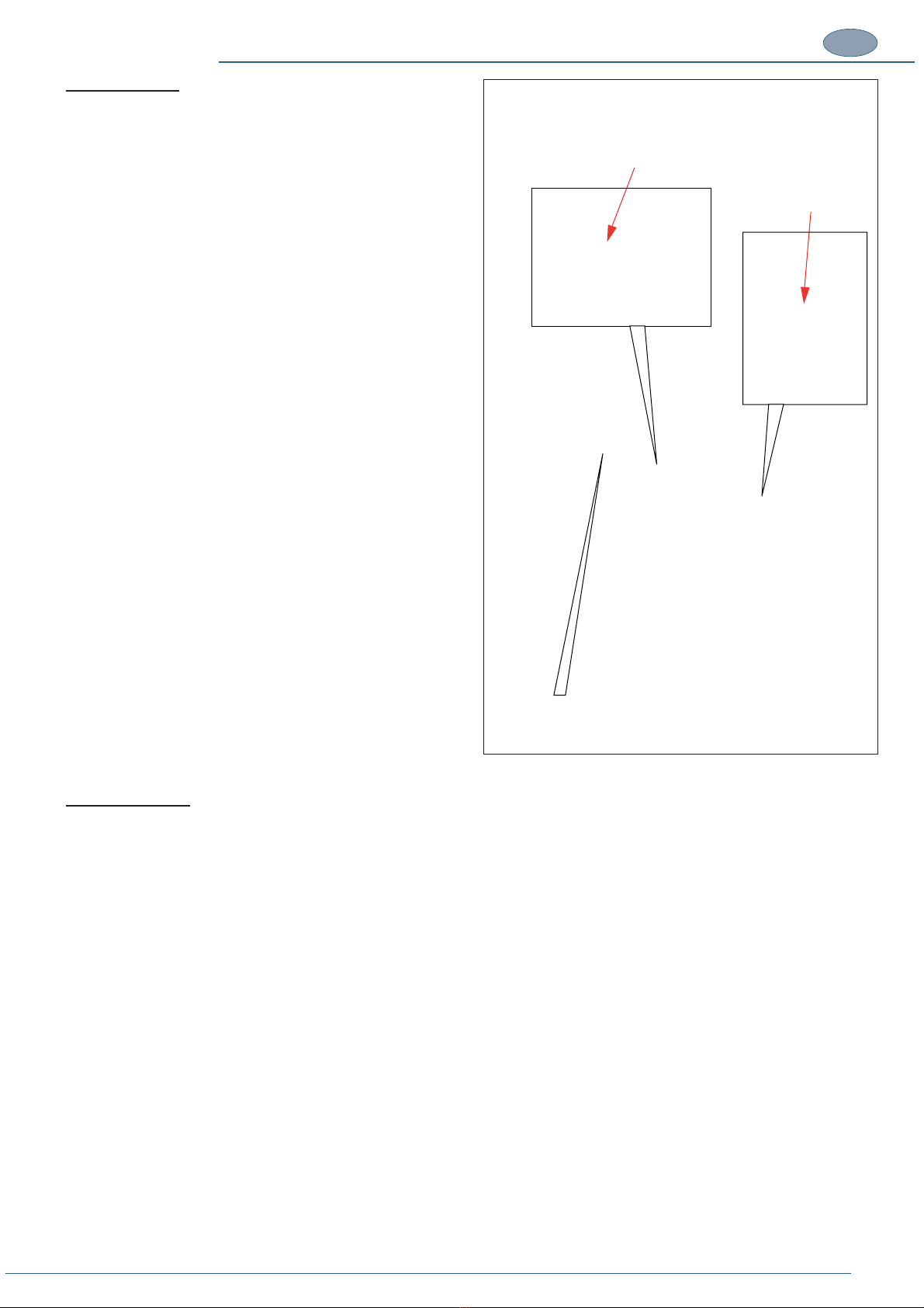
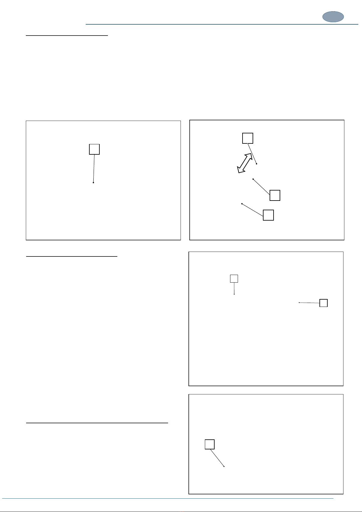
1.11. MAIN MACHINE COMPONENTS
operating units and zones, including:
(G) Working bench
(H) Stand (optional)
(I) Pneumatic pedal switch
(L) Machine casing
(M) External compressed air connections, pedal and power supply
M
G
H
I
L
A
C
E
D
B
F
12 TRANSLATION OF THE ORIGINAL INSTRUCTIONS (Keep for future reference)
Document Code Rev. Date saved Date printed
U300 INSTRUCTIONS 01 09/02/2016 09/02/2016
EN
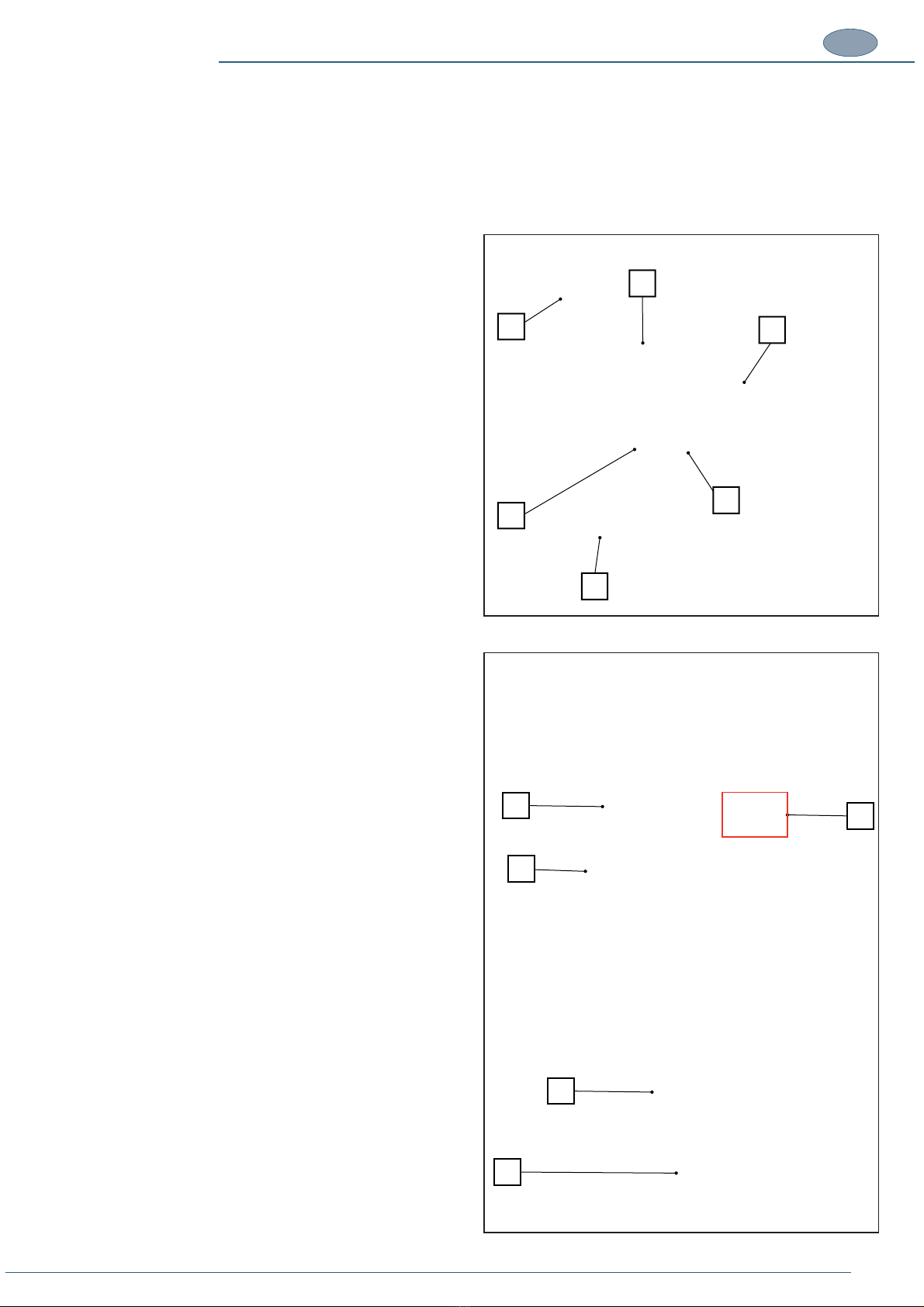
The working bench is the surface on which manual operations take
the operator controls.
It is made up of the following main parts:
(A) Vertical moulding clamp unit
(B) Alignment guides unit
(D) Front moulding clamp unit
(E) AFC brake
(H) EC safeguard
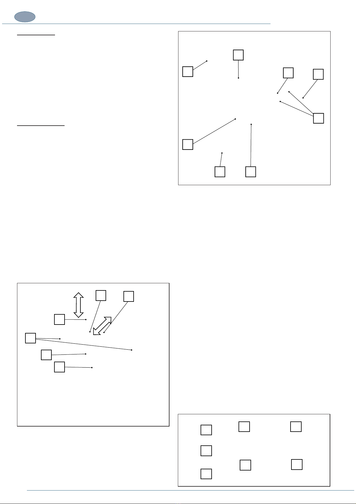
Vertical clamp unit
This unit is designed to immobilize the mouldings on the working
bench and counteract the V-nailing force.
and is therefore in line with the direction of V-nail insertion.
It is important that the air pressure applied to the vertical clamp
provides thrust which is always higher than the thrust of the V-nails,
if this is not the case, V-nail insertion could result in the mouldings
being lifted up, resulting in incomplete insertion of the V-nail and a
The unit is made up of a mechanical or magnetic stopper holder to
which the interchangeable rubber stoppers (P) of varying hardness
are applied, located at the bottom of a punched column (N) which
can be positioned at various heights depending on the size of the
frame.
The assembly is fastened to two sturdy columns (S) the movement
of which is controlled by pneumatic actuators. The punched column
is installed on a support (R) which makes it possible to carry out
The vertical stopper unit is made up of the following main parts:
(N) Punched rod - allows the operator to position the stopper at
(O) Screw for fastening and for rapid changeover of the
(P) Stopper holder, which may be mechanical or magnetic
depending on the type of accessories used.
(Q) Click knob for blocking the column.
(R) Rod support arm.
(S) Piston stem vertically activated by the pneumatic actuator.
Stoppers available on request:
T) Mechanical stopper holder.
U) Interchangeable stopper - soft (blue).
V) Interchangeable stopper - medium (yellow).
W) Interchangeable stopper - hard (black).
X) Round magnetic felt stopper.
Y) Corner magnetic stopper holder.
Z) Magnetic support.
T
U
W
V
Z
YX
Q
S
O
P
N
R
A
C
B
F
E
G
D
H

13
TRANSLATION OF THE ORIGINAL INSTRUCTIONS (Keep for future reference)
Document Code Rev. Date saved Date printed
U300 INSTRUCTIONS 01 09/02/2016 09/02/2016 EN
In the U300 machine, the magazine (E) can hold V-nails of different
heights but only one V-nail height can be used at a time, depending
on the nailing head installed.
When the size of the V-nails is changed the nailing head must also
be switched over to match the V-nails used.
The V-nails are held in position by the V-nail pusher device (F).
Head and L-block support are designed to guide the V-nails during
the thrust action of the hammer and their insertion into the overlying
mouldings.
The magazine is in turn brought up against the L-block support and
by means of a V-nail pusher supplies and aligns the V-nails against
the guide each time the hammer is activated.
The hammer is activated by a pneumatic cylinder which is controlled
by the pneumatic pedal.
Perfect mechanical alignment of these parts ensures precise
insertion, single or multiple, of the V-nails in the mouldings to be
(A) Screw for fastening the head.
(B) Head of different heights.
(C) L-block support
(D) Hammer
(E) V-nail magazine
(F) V-nail pusher which keeps the V-nails at a constant pressure
(G) PLV selector lever:
in the OFF position (open) it draws the V-nail pusher back so
in the ON position (closed) the V-nail pusher pushes the
does not work.
G
ABCDE
F
14 TRANSLATION OF THE ORIGINAL INSTRUCTIONS (Keep for future reference)
Document Code Rev. Date saved Date printed
U300 INSTRUCTIONS 01 09/02/2016 09/02/2016
EN
In the U300 machine, the magazine (E) can hold V-nails of different
heights but only one V-nail height can be used at a time, depending
on the nailing head installed.
When the size of the V-nails is changed the nailing head must also
be switched over to match the V-nails used.
The V-nails are held in position by the V-nail pusher device (F).
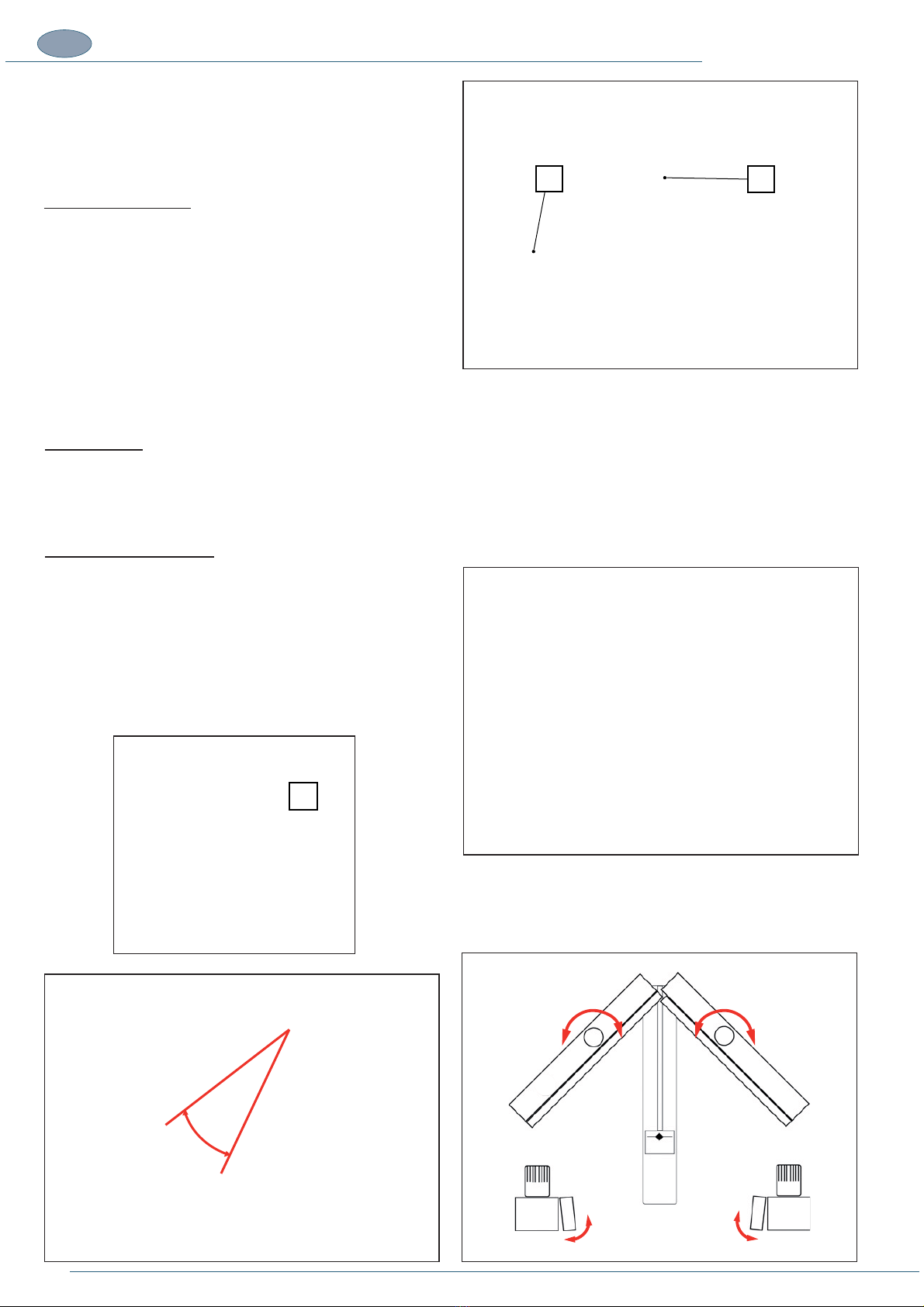
The alignment guide unit, positioned on the working bench, can slide
the operator based on the size of the moulding in relation to the
position of the front clamp (rod clamp).
Fixed fences for 120° and 135° corners may also be installed in the
fence support (A) for making frames with 6 and 8 sides respectively
(available as optional accessories).
AFC brake unit
The AFC brake unit (B) is made up of a pneumatically activated
device which comes into operation during the nailing cycle.
The unit is designed to lock the position of the mobile fence and
oppose the horizontal thrust of the rod clamp.
the work bench.
Mouldings may have a slanting edge which would make the action
of the horizontal clamp ineffective. The two-knob fence is designed
rest to improve stability.
The two-knob fence can be used to improve clamping of the
mouldings during assembly.
B
A
C
15
TRANSLATION OF THE ORIGINAL INSTRUCTIONS (Keep for future reference)
Document Code Rev. Date saved Date printed
U300 INSTRUCTIONS 01 09/02/2016 09/02/2016 EN
the pedal thus clamping them against the fence unit.
Movement of the rod clamp occurs at the same time as vertical clamping and is activated by a pneumatic actuator when the pedal is
pressed. For as long as the pedal is pressed, it clamps the mouldings for the entire duration of the nailing cycle.
The front clamp is made up of:
(H) Knob for securing the rod to the pneumatic actuator of the front clamp.
(I) Holes for anchoring the cursor of the pneumatic actuator.
(L) Front locking rod clamp
bench needs to be increased by installing the two side extensions
(A) and (B) (optional).
perfectly aligned with the working bench, see heading ASSEMBLY
OF SEPARATELY SHIPPED UNITS.
(A) Right extension
(B) Left extension.
The machine is designed to be STATIC, i.e. it must be installed
structure so that it remains stationary during operation.
If detached from the stand, the machine can be used on a horizontal,
sturdy and stable table.
The machine is LOADED AND UNLOADED MANUALLY:
I. MANUAL POSITIONING OF THE MOULDINGS to be
and locked
ii. MANUAL REMOVAL OF THE ASSEMBLED MOULDINGS from
To extend the available work surface for the mouldings, it is possible
to install 6 brackets (C), 2 on each side, onto which a surface panel
in wood or other material (not supplied) is placed.
To install the brackets, please refer to the heading ASSEMBLY OF
SEPARATELY SHIPPED UNITS
(A) 90° bracket with slots and holes for fastening to the machine
and the wooden surface panel.
B
A
L
G
H
I
C

16 TRANSLATION OF THE ORIGINAL INSTRUCTIONS (Keep for future reference)
Document Code Rev. Date saved Date printed
U300 INSTRUCTIONS 01 09/02/2016 09/02/2016
EN
2. INSTALLATION
2.1. STORAGE
The machine, intended for indoor installation must be stored, if necessary, in well ventilated storage facilities and protected from dust.
oxidation caused by weather conditions.
In the case of prolonged inactivity the machine must be stored with all necessary precautions taken based on the location and expected
storage times:
1. Store the machine in an enclosed place.
2. Protect the machine from impact and stress.
3. Protect the machine from humidity and excessive temperature differences (refer to the table below).
4. Do not allow corrosive substances to come into contact with the machine.
5. Check that the pack has not been damaged and that it is perfectly dry.
including rain, snow and hail, and it must be accessible exclusively to authorized personnel.
The machine is protected in such a way as to withstand the temperatures, humidity and vibration levels typically associated with transport
and storage.
Ambient
temperature
Storing
temperature
Relative humidity
Vibrations
Atmospheric
pressure
-25 ÷ +40°C - 13 ÷ 104°F
-25 ÷ +55°C - 13 ÷ 131°F
0 ÷ +55 °C / 32 ÷ 131°F
100% at a temperature of +25°C / 77°F
Lower than 50% at a temperature of +40°C / 104°F
Lower than 90% at a temperature of +20°C / 68°F
5.9 m/s2 (0.6G) or higher 900 mbar or more
Avoid places where
there may be
unexpected changes
in temperature
which could lead
to the formation of
condensate or freezing.
Storage temperature is construed as a short-term value, e.g. during transportation. Condensation or freezing normally occurs in sites
2.2. CHECKS ON RECEPTION
NOTES
It is essential to check the packs at the time of arrival and in the precise moment in which they are received. The check is performed
in two stages for each pack received to avoid misunderstandings with the shipping agent.
Administrative check
1. Crate number and number of packs.
2. Weight and size
3. Correspondence of information on shipping document with the material effectively delivered (description, serial number, etc). The
4. Check correspondence between shipping document data and the order.
Technical check
1. Condition and intactness of packaging.
2. Check that the packaging shows no signs of visible damage caused during transport and handling operations.
All the above checks must be performed by inspection in the presence of the shipping agent’s delivery person. If any damage is noted
or the supply is incomplete or incorrect, inform the manufacturer’s sales department immediately.
NOTES
In relation to the above prescriptions, the manufacturer informs the user that in compliance with current international and national
rulings, goods are always shipped at the risk and responsibility of the purchaser and, unless otherwise stated in writing at the time
17
TRANSLATION OF THE ORIGINAL INSTRUCTIONS (Keep for future reference)
Document Code Rev. Date saved Date printed
U300 INSTRUCTIONS 01 09/02/2016 09/02/2016 EN
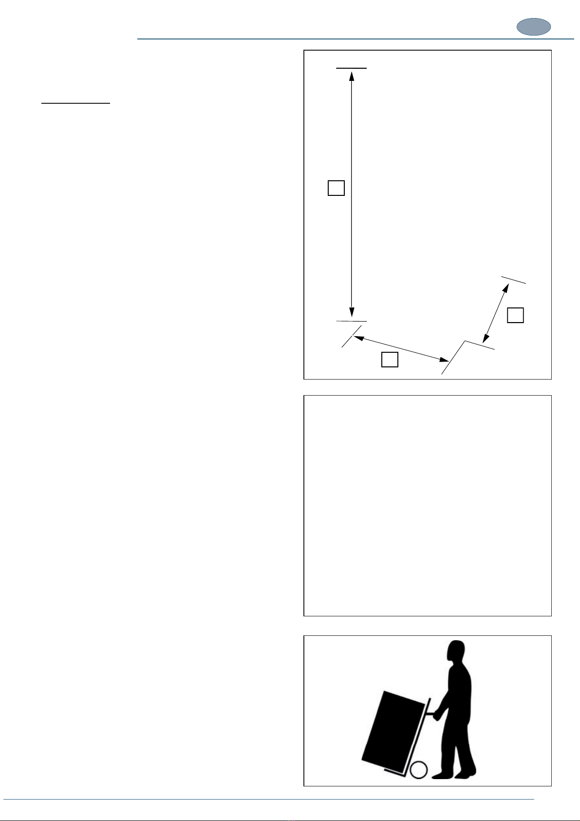
2.3. TRANSPORT, LIFTING AND HANDLING
Dimensions, weight and handling of individual machine parts
MACHINE BODY
Machine height .................................................A = 1340mm - 53’’
Machine length ................................................. B = 600mm - 24’’
Machine width .................................................. B = 500mm - 20’’
Weight of the machine ............................................. 35kg - 77 lbs
Weight of the stand ................................................. 30 kg - 66 lbs
Size of the packaging............................................... 600x440x500
2.4. LIFTING AND HANDLING
DANGER – CAUTION
to the intended installation site as possible. Said site
must be checked beforehand to obtain information
about the necessary clearances and dimensions,
procedures.
2.4. LIFTING AND HANDLING
The U300 is divided up and delivered as an assembly kit.
The machine must be transported in such a way as to avoid any
damage to its components:
· The machine must be transported in its installation position.
· Before transporting the machine, grease all non-painted parts
to avoid the risk of deterioration.
· Based on the type of transport, take care to protect the machine
from all possible impact and stress.
NOTE – The machine must be lifted by TWO operators.
NOTE –It is advisable to keep the packaging in case it is
needed to store or transport the machine at a later date.
The machine is moved on a two-wheel trolley.
A
B
C
660
500
440

18 TRANSLATION OF THE ORIGINAL INSTRUCTIONS (Keep for future reference)
Document Code Rev. Date saved Date printed
U300 INSTRUCTIONS 01 09/02/2016 09/02/2016
EN
2.5. REMOVING THE PACKAGING
The machine may be shipped in a container or on a lorry.
In both cases the same type of packing is envisaged which is suitable for guaranteeing the good condition and proper preservation of
the machine during transport up to the time of delivery to the customer.
The machine is shipped packed in a special box and protected against damage by polystyrene inserts.
Maximum dimensions 660x440x500 (AxBxC).
NOTE –It is advisable to keep the packaging in case it is needed to store or transport the machine at a later date.
When storing the machine, never stack two machines packed on a pallet with shrink wrap.
MULTIPLE TRANSPORT AND HANDLING
The transport of more than one machine can be carried out using a Europallet which can carry up to a maximum of 12 boxes (12 machines).
Overall dimensions = (80x1200x1800mm - AxBxC).
A
B
C
A
C
B
Table of contents
Other FLETCHER Industrial Equipment manuals


