FLETCHER Alfamacchine U200P User manual

1
TRANSLATION OF THE ORIGINAL INSTRUCTIONS (Keep for future reference)
Document Code Rev. Date saved Date printed
U200P INSTRUCTIONS 01 30/06/2016 30/06/2016 EN
TRANSLATION OF THE ORIGINAL INSTRUCTIONS (Keep for future reference)
PLEASE RETAIN FOR FUTURE REFERENCE
Name
Function
Model / Type
Serial number
Year of construction
Manual Revision
FRAME ASSEMBLING MACHINE
ASSEMBLY OF FRAMES BY INSERTION OF METAL V-NAILS
U200P
2016
EN INSTRUCTIONS MANUAL

2
TRANSLATION OF THE ORIGINAL INSTRUCTIONS (Keep for future reference)
Document Code Rev. Date saved Date printed
U200P INSTRUCTIONS 01 30/06/2016 30/06/2016
EN

1
TRANSLATION OF THE ORIGINAL INSTRUCTIONS (Keep for future reference)
Document Code Rev. Date saved Date printed
U200P INSTRUCTIONS 01 30/06/2016 30/06/2016 EN
TRANSLATION OF THE ORIGINAL INSTRUCTIONS
EN
1. INTRODUCTION TO USE......................................................................................................................................................... 2
1.1. HOW TO CONSULT THIS MANUAL AND THE SYMBOLS ADOPTED ....................................................................... 2
1.2. WARNING-SAFETYALERTDECALS(seegure)..................................................................................................... 2
1.3. TYPE OF USE AND CONTRAINDICATIONS............................................................................................................... 3
1.4. TECHNICAL CHARACTERISTICS............................................................................................................................... 6
1.5. PRODUCTS PROCESSED - HANDLED OR GENERATED ........................................................................................ 7
1.6. EMISSION OF AIRBORNE NOISE............................................................................................................................... 7
1.7. RESIDUAL RISKS - GENERAL INFORMATION .......................................................................................................... 7
1.8. RESIDUAL RISKS ........................................................................................................................................................ 8
1.9. DESCRIPTION OF SAFETY FUNCTIONS................................................................................................................... 9
1.10. MACHINE DESCRIPTION.......................................................................................................................................... 10
1.11. MAIN MACHINE COMPONENTS ............................................................................................................................... 10
2. INSTALLATION ....................................................................................................................................................................... 14
2.1. STORING.................................................................................................................................................................... 14
2.2. CHECKS ON RECEPTION......................................................................................................................................... 14
2.3. TRANSPORT, LIFTING AND HANDLING................................................................................................................... 15
2.4. LIFTING AND HANDLING .......................................................................................................................................... 15
3. PRELIMINARY PREPARATION AND ADJUSTMENT PROCEDURES ................................................................................. 17
3.1. PUTTING THE MACHINE INTO SERVICE ................................................................................................................ 17
3.2. POSITIONING (IF OPTIONAL STAND HAS BEEN PURCHASED) ........................................................................... 17
LEVELLING THE MACHINE (MOUNTED ON STAND) ....................................................................................................... 18
3.3. ASSEMBLY OF SEPARATELY SHIPPED UNITS....................................................................................................... 22
4. INITIAL START-UP AND USE OF THE MACHINE................................................................................................................. 23
4.1. PNEUMATIC SUPPLY ................................................................................................................................................ 23
4.2. WORKSTATIONS AND OPERATORS' TASKS........................................................................................................... 25
4.3. CHECKS, ADJUSTMENTS AND START-UP .............................................................................................................. 26
4.4. START-UP................................................................................................................................................................... 26
4.5. WORK CYCLE............................................................................................................................................................ 38
5. MAINTENANCE, TROUBLESHOOTING AND CLEANING ................................................................................................... 40
5.1. MAINTENANCE TECHNICIAN REQUIREMENTS ..................................................................................................... 40
5.2. WORK STATIONS AND MAINTENANCE TECHNICIAN DUTIES.............................................................................. 40
5.3. MAINTENANCE PRESCRIPTIONS............................................................................................................................ 40
5.4. GENERAL WARNINGS .............................................................................................................................................. 41
5.5. ISOLATION FROM EXTERNAL ENERGY SOURCES............................................................................................... 41
5.6. ROUTINE MAINTENANCE......................................................................................................................................... 41
5.7. TASKS THAT CAN BE PERFORMED BY THE OPERATOR ..................................................................................... 42
5.8. TASKS THAT CAN BE PERFORMED ONLY BY MAINTENANCE TECHNICIANS ................................................... 43
5.9. CLEANING.................................................................................................................................................................. 46
6. TROUBLESHOOTING AND RELEASE OF MOVING PARTS ............................................................................................... 49
7. REINSTALLATION AND REUSE ............................................................................................................................................ 51
8. EXTINGUISHING MEDIA........................................................................................................................................................ 51
9. SCRAPPING AND DISPOSAL................................................................................................................................................ 51
9.1. SCRAPPING............................................................................................................................................................... 51
9.2. DISPOSAL .................................................................................................................................................................. 52
TABLE 1 - MACHINE UNIT .............................................................................................................................................................. 53
TABLE 2 - HEAD UNIT..................................................................................................................................................................... 54
TABLE 3 - CROSSBAR AND COLUMNS UNIT .............................................................................................................................. 55
TABLE 4 - FENCE UNIT................................................................................................................................................................... 56
TABLE 5 - V-NAIL PUSHER UNIT ................................................................................................................................................... 56
TABLE 6 - STAND UNIT................................................................................................................................................................... 57

2
TRANSLATION OF THE ORIGINAL INSTRUCTIONS (Keep for future reference)
Document Code Rev. Date saved Date printed
U200P INSTRUCTIONS 01 30/06/2016 30/06/2016
EN
DANGER - WARNING
BEFORE USING THE MACHINE PLEASE READ THIS MANUAL CAREFULLY SO THAT YOU BECOME FAMILIAR
WITH THE MACHINE, ITS ENVISAGED USE AND ANY RISKS ASSOCIATED WITH IT.
KeeptheUseandMaintenanceManualingoodcondition:Remember,itisanintegralpartofthemachine.Alwaysrefertothemanual
togetbestmachineperformanceinmaximumsafetywhileperformingtheoperationsdescribedtherein.
Thismanualmustbekeptinaneasilyaccessibleplace,nearthemachine,atalltimessothatitcanbeconsultedwhenevernecessary.
DANGER - WARNING
USE THE MACHINE SOLELY AND EXCLUSIVELY FOR THE USES INDICATED AND IN ACCORDANCE WITH THE
RECOMMENDATIONS PROVIDED IN THIS MANUAL. NEVER TAMPER WITH IT, FORCE IT OR USE IT IN ANY
INAPPROPRIATE MANNER.
1. INTRODUCTION TO USE
1.1. HOW TO CONSULT THIS MANUAL AND THE SYMBOLS ADOPTED
Pleasepayparticularattentiontothewords“DANGER–WARNING”,“DANGER–CAUTION"and“NOTE”asusedinthismanual.
To draw the user’s attention to certain information and provide warning messages, the operations described in this manual are
accompaniedbysymbolsandnotes tohighlight thepresenceofanyhazardsandindicate thesafe useoftheequipment.These
symbolsandnotesbelongtovariouscategoriesasindicatedbelow:
DANGER – WARNING: IMPORTANT INFORMATION CONCERNING GENERAL SAFETY.
DANGER-CAUTION: highlights situations where careful and sensible actions are essential.
NOTES: information of a technical nature.
1.2. WARNINGSTICKERS-INDICATIONS(seegure)
Sticker Description
Wearprotectivegoggles.
Wearprotectivegloves.
Wearsafetyfootwear
Wear ear defenders.
Riskofimpactagainstobstacles:afxedon
thecornersoftheguards.

3
TRANSLATION OF THE ORIGINAL INSTRUCTIONS (Keep for future reference)
Document Code Rev. Date saved Date printed
U200P INSTRUCTIONS 01 30/06/2016 30/06/2016 EN
1.3. TYPE OF USE AND CONTRAINDICATIONS.
GENERAL WARNINGS
Theoperatormustreadalltheinformationinthismanualcarefully,payingspecialattentiontothesafetyprecautionslistedinthischapter.
ItisalsoessentialfortheOperatortoabidebythefollowingwarnings:
· Alwayskeepthemachineandworkareacleanandtidy.
· Arrangesuitablecontainersforstoringtheworkpiecestobeprocessedandthosethathavealreadybeencompleted.
· NEVERusethemachinewhennotingoodpsycho-physiologicalcondition.
· Alwayswearsuitableworkweartoavoidanyhindrancesand/orhazardousentanglementinmachineparts.
· PersonnelmustbeauthorizedandtrainedbeforehandonmachineusebyAlfamacchinetechnicians.
· Wearallnecessarypersonalprotectiveequipment:safetyfootwear,glovesandprotectiveglasses
· TheoperatormustwearpersonalprotectiveequipmentindicatedintheInstructionManual,inaccordancewiththeoperationsto
carry out.
· NeverremoveoralterthedataplatesafxedtothemachinebytheManufacturer.
· Keepngerswellawayfromtheoperatingarea.
· Keepfeetawayfromthepedalduringmachineadjustmentoperations.
PERMITTED USE
Themachinedescribedhereinisdesignedtoberunby1operatorsuitablytrainedandinstructedwithregardtoresidualrisks.The
operatormusthavethesameskills,intermsofsafety,asthemaintenancetechniciansandadequateprofessionalcompetence.
DuringitsPERMITTEDANDREASONABLYPREDICTABLEUSE,themachinemaybeusedexclusively:
• toworkwithwoodenmouldingsofvarioushardness,withmultiplesurfacenishes,forthepurposeofmakingframesforpictures,
mirrors,displaycases,cupboarddoorsetc.)inaccordancewiththecharacteristicsdescribedintheheading“ProductsProcessed
-HandledorGenerated”.Useofthemachinetoperformprocessesotherthanthosedescribedinthismanualistobeconsidered
improper and therefore strictly prohibited.
• withtheproducts(andmaterials)describedandhavingthedimensionsspeciedintheheading“TECHNICALCHARACTERISTICS”
Itisalsocompulsory:
• forthemachinetobeusedbyoneoperatoronlywhohasreceivedadequatetraining/informationconcerningmachineoperations,
performanceandanyhazardsassociatedwithitsuse.
• toensurenoexposedpersonsarepresentinthemachine’soperatingareabeforeproceedingwithanyoperationswhatsoever.
• tochecktheperfectconditionofallthesafetydevicesbeforestartingtoworkwiththemachine.
• toensure,whenthemachineisplacedonthefactoryoorwhereitistobeused,thatitisinstalledonalevel,smoothandperfectly
horizontalsurface.Theoormusthaveanadequateloadbearingcapacitytosupporttheweightofthemachine.
• tocheck,priortostartingworkwiththemachine,theconditionsofambientlightingandensuretherearenoareasofshadow,glare,
orpotentiallyhazardousstrobeeffects.
• todisconnect,priortostartinganyworkonthemachine,themaincompressedairsupplies,tosafelydischargeanyresidualenergy
inthemachinecircuits,andwaitforallpartsathightemperaturestocooldownadequately.
UNINTENDED USE
DANGER - WARNING
THE MACHINE MUST NOT BE USED IN A PROHIBITED MANNER. SPECIFICALLY:
• itcannotbeoperatedwithparametersdifferenttothoseshowninthe“TECHNICALCHARACTERISTICS”tableorwithproducts
and/ormaterialswithdifferentcharacteristicstothosepreviouslydescribedintheheading“TECHNICALCHARACTERISTICS”.
• all uses of the machine other than those described in this manual are construed as improper and as such the manufacturer declines
all liability
• theuserisresponsibleforanydamageresultingfromfailuretoobservetheoperatingconditionsagreedatthetimeoftechnical
specicationandorderconrmation

4
TRANSLATION OF THE ORIGINAL INSTRUCTIONS (Keep for future reference)
Document Code Rev. Date saved Date printed
U200P INSTRUCTIONS 01 30/06/2016 30/06/2016
EN
FORBIDDEN USE
DANGER - WARNING
FURTHERMORE IT IS PROHIBITED TO USE THE MACHINE IN AN INCORRECT MANNER, IN PARTICULAR:
• never leave the loaded machine unattended
• neveruseammable,corrosiveortoxicsubstancestocleanthemachine
• neverallowunauthorizedpersonneltousethemachine
• neversmokeoruseopenameequipmentorhandleincandescentmaterial,unlessadequatesafetymeasureshavebeenadopted
• neveractivateoradjustthecontrolandlockingdevices,suchasknobsorsimilardevices,duringmachineoperationorwhennot
authorizedtodoso
• neverhangobjectsorweightsonthemachine
• neverusethemachinewiththesafetyguardsopen,incorrectlyfastened,orremoved
• neverusethemachinewiththesafetymicroswitchesandinterlockingsafetydevicesinhibitedand,ingeneral,withanysafetyand/
or protective device (mechanical) deactivated and/or non-functional
• neverpartiallyortotallyby-pass,remove,modifyorinanywayrenderineffectivetheguards,safetymicroswitchesandwarning
signs
• useofthemachineisforbiddenwhentheuserhasnotadoptedallthenecessarymeasurestoeliminatetheresidualrisksas
indicated in this instruction manual
• neverusethemachineforoperationsotherthanthoseexplicitlyindicatedinthisinstructionmanual.
• neverusethemachineinenvironmentsforwhichithasnotbeendesignedunlessallnecessarysafetymeasureshavebeenadopted
beforehand.
• the machine must not be used by untrained personnel
• foodstuffsmustnotbebroughtintocontactwiththemachine
• itisprohibitedtoactivatethecontroldevicesformachinemovementswithoutrstcheckingandascertainingtheabsenceofpersons
inthedangerareassubjecttomachinemovements
• itisprohibitedtoentertheoperating/dangerzoneofthemachineduringcontrolofthemachine’smovingparts
• itisprohibitedtoenterthemachineworkingareawithanypartofthebody,handsandarmsincluded,beforehazardousmoving
elements have come to a complete standstill.
• itisprohibitedforthemachineoperatorandmaintenancetechniciantoenterthedangerzonestoperformcleaning,lubrication,
maintenanceoperationsetc.withouthavingrstsetthepowercut-offswitchesto“ZERO”andpadlockedtheminthisposition.
• themachinemustnotbeusedincriticalconditionsofstability,i.e.:
• whenplacedonasupportsurfacewhichisnotperfectlyhorizontalandsmooth,ordoesnothaveaninadequateloadcapacity
as indicated in this manual;
- outdoorsorworksiteswithopenwindowsanddoors.
• thefollowingarestrictlyprohibited:
- processingofmaterialsandproductsthatarenotexpresslyindicatedinthismanual
- processingofmetalmaterialsmadeofaluminium,lightweightalloys,andsteelanditsalloys
DANGER – CAUTION
The manufacturer cannot be held liable for any faults caused by unreasonable, improper and/or incorrect use of the
machine.
Theuserisanywayresponsibleforalldamagederivingfromfailuretocomplywiththespeciedtermsofuse.Foranyfurtherinformation
alwaysconsultthemanufacturer’sengineeringdepartment.
Theuserisalwaysresponsibleforprovidingsuitablepersonalprotectiveequipmenttomachineoperatorsandforinformingthemon
the permissible uses of the machine

5
TRANSLATION OF THE ORIGINAL INSTRUCTIONS (Keep for future reference)
Document Code Rev. Date saved Date printed
U200P INSTRUCTIONS 01 30/06/2016 30/06/2016 EN
PERSONNEL AUTHORIZED TO USE THE MACHINE
Thismachinehasbeendesignedandmanufacturedtobeusedbyqualiedpersonnelwithadequatetraining,experienceandskills
inaccordancewiththecharacteristicsdescribedbelow:
Operators/Apprentices:
• may be male or female;
• mustbeaged14orover;
• must have full use of both hands;
• must have no physical or mental disabilities;
• mustknowandfullyunderstandthecontentsoftheusermanual.
PERMITTED AMBIENT CONDITIONS AND OPERATING LIMITS
DANGER - WARNING
THIS MACHINE IS NOT SUITABLE FOR USE IN POTENTIALLY EXPLOSIVE ENVIRONMENTS.
THEREFORE IT IS PROHIBITED TO INSTALL OR USE IT IN ANY SUCH ENVIRONMENT.
SERVICE CONDITIONS
SERVICE CONDITION USER LIMITS
Installation type Indoor
Floorconditions Horizontalandsmooth:irregularityandgradienttolerancewithin
2%
Supportingsurfacecharacteristics Flooringincompliancewithhealthandsafetyrequirementsinthe
workplaceinaccordancewithallapplicablelegislation
Maximumambientairtemperature +40°C/104°F
Minimumambientairtemperature 5°C/104°F(iftheelectricalequipmentasaprotectionratingofat
leastIP54)0°C/32°F(iftheelectricalequipmenthasaprotection
ratinglowerthanIP54)
Ambientworkingtemperature +5°C<T<+45°C/113°F
Transportandstoragetemperature between-25°C/-13°Fand+55°C/131°F(temperaturesofup
to+70°C/158°Fareadmissibleforperiodsoflessthan24h)
Maximumaltitudeabovesealevel 1000m
Minimumrequiredlightintensity 600lux
Relativehumidityof100%at+25°C/77°F(electricalequipmentprotectionratingofatleastIP54)
Relativehumidityshallnotexceed50%at+40°C/104°For90%at+20°C/68°F(electricalequipmentprotectionratingbelowIP54)
Equipmentformachinedesignedforindoorinstallations
Machine NOT suitable for operation in contaminated atmospheres: for example, dusts, acids, corrosive gases, salt or similar
contaminants.
Machine NOTsuitableforoperatinginpotentiallyexplosiveatmospheresclassiedaszone0,zone1orzone2.
Machine NOTsuitableforoperationinenvironmentssubjecttothepresenceofionizingandnon-ionizingradiation:forexample,
microwaves,UVrays,laser,X-rays,andsimilar.
ElectricalequipmentNOTsuitableforinstallationonmachinesorforoperationinplacessubjecttovibrationandimpact:otherwise,
installequipmentwellclearofsourceofvibrationandimpactandtantivibrationsupports.
Pollutionclassofelectricalequipmentequivalentto3(THREE)
Installationenvironmentequivalenttotwo(2)
Canbeutilisedinresidential,commercial,oflightindustrialzonesthankstocompliancewithstandardEN61000-6-1
Intendedfordirect/exclusiveserviceofindustrialprocessmachinery

6
TRANSLATION OF THE ORIGINAL INSTRUCTIONS (Keep for future reference)
Document Code Rev. Date saved Date printed
U200P INSTRUCTIONS 01 30/06/2016 30/06/2016
EN
SERVICE CONDITIONUSER LIMITS
Specialandadditionalprescriptions,notenvisaged,
mayberequestedformachinesintendedfor:
• outdoor use;
• handlingpotentiallyexplosivematerials;
• useinpotentiallyexplosiveand/orammableatmospheres;
• use involving specic risks in the processing of specic
materials;
• use in mines;
• useinrefrigerationplants;
• useathightemperatures;
• use in corrosive environments;
• useinstrongmagneticelds;
• use in radioactive conditions;
• usefor loadsthenature ofwhich couldleadto hazardous
situations(forexample,moltenmetal,acids/bases,particularly
fragileloads,explosives),
• useonshipsandareasaffectedbyearthquakes;
• food-contact use;
• use in public areas;
•useinaircraftgroundsupport.
1.4. TECHNICAL CHARACTERISTICS
Machinecharacteristics
Workingbenchdimensions(WxL)...................................................................................................................... 300x450mm-13”x18”
Maximummachineheight...................................................................................................................................................450mm-51”
Machineweight....................................................................................................................................................................32kg-83lbs
V-nailmagazinecapacity.............................................................................................................................................................220pcs
Max.quantityofV-nailsinsertedperposition..................................................................................................................................9pcs
V-Nail insertion positions ............................................................................................................................................................Multiple
Max.distancebetweennails ...................................................................................................................................................... 180mm
Minimum/maximumwidthofmoulding .............................................................................................................6/130mm-¼”–5”1/8
Minimum/maximumheightofmoulding...............................................................................................................6/80mm-¼”–3”1/4
V-nailcharacteristics
Height ................................................................................................................................................................................. 7-10-12 mm
Heightofoptionalheads........................................................................................................................................................3-5-15 mm
Compressedairsupply
Maximumpermittedinletpressure .................................................................................................................................................. 8bar
Operatingpressure.................................................................................................................................................................. 2 ... 8 bar
Specicairconsumption...................................................................................................................................................................3 Nl
V-nailcharacteristics
V-nailtype Heightmm
H3 3mm (optional)
H5 5mm
H7 7mm
H10 10mm
H12 12mm
H15 15mm

7
TRANSLATION OF THE ORIGINAL INSTRUCTIONS (Keep for future reference)
Document Code Rev. Date saved Date printed
U200P INSTRUCTIONS 01 30/06/2016 30/06/2016 EN
Material Recommendedsharpness
Softwoods
and plastic
SW
transparent stick
Mediumwood MW
brownstick
Hardwood HW
greenstick
Very Hard Wood
and MDF
HS
red stick
1.5. PRODUCTS PROCESSED - HANDLED OR GENERATED
Theproductshandledbythemachinedescribedhereinmustbemadeupofwoodenmouldingsofvarioushardness,withmultiple
surfacenishes,forthepurposeofmakingframesforpictures,mirrors,displaycases,cupboarddoorsetc..
Themaintechnicalcharacteristicsoftheproductshandledbythemachinedescribedhereinareprovidedbelow.
DESCRIPTION OF PRODUCTS HANDLED CHARACTERISTICS
Minimum/maximumproleheight 6-80mm
Minimum/maximumprolewidth 6-130mm
1.6. EMISSION OF AIRBORNE NOISE
NOTE – The manufacturer declares, under his own responsibility, that the machine produces a continuous equivalent A-weighted
sound pressure level of 72 dB.
DANGER – WARNING:
TO AVOID THE DANGER OF HEARING DAMAGE CAUSED BY SHRILL OR INSISTENT NOISE, THE MACHINE
OPERATOR AND MAINTENANCE TECHNICIAN MUST ALWAYS USE APPROPRIATE HEARING PROTECTION, SUCH
AS HEARING DEFENDERS OR EARPLUGS.
1.7. RESIDUAL RISKS - GENERAL INFORMATION
Thismanualcontainsalistanddescriptionoftheresidualrisksthatcouldnotbeeliminatedinthedesignstageandthattherefore
remain present on the machine.
Foreachrisk,suitableinstructionsorprescriptionsaregivenwhichtheusermustobserveinordertoavoidhazardsaffectingthe
machineoperator,maintenancetechnicians,anyexposedpersonsandthemachineitself.

8
A
TRANSLATION OF THE ORIGINAL INSTRUCTIONS (Keep for future reference)
Document Code Rev. Date saved Date printed
U200P INSTRUCTIONS 01 30/06/2016 30/06/2016
EN
1.8. RESIDUAL RISKS
Foreachrisk,suitableinstructionsorprescriptionsaregivenwhichtheusermustobserveinordertoavoidhazardsaffectingthe
machineoperator,maintenancetechnicians,anyexposedpersonsandthemachineitself.
Residualriskofngercrushing
Duringthenormaloperatingcycleandduringmaintenance,Operatorsareexposedtocertainresidualriskswhich,duetothenature
of the operations could not be completely eliminated.
-Fingercrushinghazardintheoperatingareaoftheverticalclamp(A).
Furthermore,itistobepointedoutthatsaidngercrushingrisksarepresentneareachmobileelementinstalledoverthemachine’s
workingbench.
Consequentlytheoperatorandmaintenancetechnician,aswellasobservingtheinstructionsprovidedinthismanual,mustnever
placetheirngersoranyotherpartofthebodyinthezoneindicated.
What’smore,workersmustneverwearrings,wristwatches,jewellery,tornclothing,scarves,tiesoranyotherlooseclothingorpersonal
accessoriesthatmayconstitutearisk.Makesuresleevestsnuglyaroundwristsandkeeplonghairtiedback.
Residualriskduetothecombustibilityofthesubstancesusedinthemachineandtheproductshandledbythesame
Toavoidthehazardsresultingfrom:
• theignitionofsubstancesusedinthemachine;
• residualrisksassociatedwithpossibleoutbreaksofre;
theemployer,inadditiontotrainingandadequatelyinformingthemachineoperatorandmaintenancetechnicianonsuchrisks,must
providepermanentreprotectionsystemsinthevicinityofthemachinecontrolstation.Saidsystemsmustbesuitableforthetypes
ofmaterialwhichcouldcatchre.
PPEtobeused:
Protectivegloves Safetyfootwear Safetyclothing Hearingprotection
Residualriskduetonoise
Asdemonstratedbyexperimentaltests,themachineproducesacontinuousequivalentA-weightedsoundpressurelevelof70dB.
Toavoidtheriskofhearingdamagecausedbyshrillorinsistentnoiseduringmachineuse,inadditiontobeingadequatelyinformed
andtrained,theoperatorandmaintenancetechnicianmustalwaysuseappropriatehearingprotection,suchashearingdefenders,
earplugsorsimilarpersonalprotectionequipmenttosafeguardhearing.

9
TRANSLATION OF THE ORIGINAL INSTRUCTIONS (Keep for future reference)
Document Code Rev. Date saved Date printed
U200P INSTRUCTIONS 01 30/06/2016 30/06/2016 EN
Residualriskcausedbypilotingthevalves
Thereisaresidualriskforthemaintenancetechnician,whenthesafetyguardsareopenandthevalvepilotsareactivated,inorder
tocheck(duringtroubleshootingprocedures)theoperationofthepneumaticallyoperatedmobileelements,whenenergy
remainsaccumulatedintheactuatorcylinders.
Consequently,whentheaforementionedactivitiesareperformed,themaintenancetechnicianmustmakesurethatnoexposedpersons
are found near the pneumatically controlled mobile elements and in any case said mobile elements must only be activated if strictly
necessaryforpinpointingoperatingfaults.
Residualriskduetothepresenceofaccumulatedenergyinsidethepneumaticactuatorcylinders
Thereisaresidualriskforthemaintenancetechnicianwhenthemachineisisolatedfromthecompressedairnetwork,duetothe
presenceofaccumulatedenergyinsidetheactuatorcylinders,whenmobileguardsareopencausedbythepresenceofclosed-
centrevalvesand/ortankswhichremainpressurized.
Pleasenotethatsaidpipingisdulyidentiedandindicatedtodistinguishitfromallotherpipinginstalledonthemachine.
Consequently,beforecarryingoutanyworkontheaforementionedcylinders,inaccordancewiththeinstructionsgivenintheactuator
manuals, the maintenance technician must neutralise the accumulated energy working in compliance with the safety regulations
applicable to maintenance personnel, such as, for example, manual activation of the special tool for the piloting valves used to
dischargestoredenergy.
Undernocircumstancesmustthepipingbedisconnectediftheystillholdresidualpressure.
1.9. DESCRIPTION OF SAFETY FUNCTIONS
Protectivedevicesinstalledonthemachine
DANGER - WARNING
IT IS STRICTLY PROHIBITED TO REMOVE THE PROTECTIONS AND SAFETY DEVICES EXCEPT WHEN STRICTLY
NECESSARY FOR THE PURPOSE OF CARRYING OUT MAINTENANCE WORK.
Whensuchprotectionsandsafetydevicesneedtoberemovedallnecessarymeasuresmustbeadoptedtohighlightthissituation
immediatelyandminimiseanypossibleassociatedhazards.
Theprotectionsandsafetydevicesmustberettedassoonasthereasonsfortheirtemporaryremovalarenolongerapplicable.
Eachoperatingunitofthemachineisprotectedbyaguard,whichmayalsobeaxedguarddesignedtopreventaccesstodangerous
parts,except:
• intheupperpartoftheworkingbenchtoperformadjustments,tooling,partsreplacement,etc.
• inthelowerpartoftheworkingbenchtoperformadjustments,tooling,partsreplacement,etc.

10
A
D
E
C
B
TRANSLATION OF THE ORIGINAL INSTRUCTIONS (Keep for future reference)
Document Code Rev. Date saved Date printed
U200P INSTRUCTIONS 01 30/06/2016 30/06/2016
EN
1.10. MACHINE DESCRIPTION
TheU200Pframeassemblingmachinehasbeendesignedtoassembleeverykindofframe.
TheU200P,withitssimpleandeasy-to-useconstruction,canexecuteprecisejoinsofanytypeofmouldingusingspecialsteelV-nails.
ItcanoperatewithnormalV-nails,reinforcedV-nailsforveryhardwoodandspecialALFAGRAFV-nailswith“pullingpower”ofvarious
heights.
1.11. MAIN MACHINE COMPONENTS
Theequipmentlistedbelowreferstostandardmachines.
Consequently,anyspecialsuppliesmayhavesomedifferentcomponentstothoselisted.
Afterremovingthemachinefromthepackaging,makesurethefollowingaccessoriesarepresent:
• 1 head for 7-mm V-nails;
• 1 head for 10-mm V-nails;
• 1 Head for 12-mm V-nails;
• 1 Mechanical stopper holder;
• 1Magneticsupport;
• 1interchangeablestopper-soft(lightblue);
• 1Interchangeablestopper-medium(yellow);
• 1Interchangeablestopper-hard(black);
• 1Roundmagneticfeltstopper;
• 1Wrench(5-mm)forchangingheads;
• 1 Wrench (6-mm) for machine assembly;
• 1Rodwithmagnets(pencilmagnet)forV-nailremoval;
• 1Fixed90°fence;
• Singleclamp;
• Stand (optional);
• Instruction Manual.
Themaincomponentsthatmakeupthemachineare:
•Workingbench
Theworking benchisthe surfaceonwhich manualoperations
take place to move, clamp and join the frame mouldings, also
incorporatingalltheoperatorcontrols.
Itismadeupofthefollowingmainparts:
(A)Verticalmouldingclampunit
(B) Alignmentguidesunit
(C) V-nailringunitandmagazine
(D) Clampingunitsairpressureadjustment
(E) Alignmentguidemovementtravelstopadjustmentunit
Verticalclampunit
Thisunitisdesignedtoimmobilizethemouldingsontheworking
benchandcounteracttheV-nailingforce.
Itspositionensuresthatthestopperisalignedwiththeringhead
andisthereforeinlinewiththedirectionofV-nailinsertion.
It is important that the air pressure applied to the vertical clamp
providesthrustwhichisalwayshigherthanthethrustoftheV-nails,
ifthisisnotthecase,V-nailinsertioncouldresultinthemouldings
beingliftedup,resultinginincompleteinsertionoftheV-nailand
apoorqualityjoin.
Theunitismadeupofamechanicalormagneticstopperholder
(P) to which the interchangeable rubber stoppers of varying
hardness are applied, located at the bottom of a punched column
(N)whichcanbepositionedatvariousheightsdependingonthe
sizeoftheframe.
Theassemblyisfastenedtotwosturdycolumns(S)themovement
ofwhichiscontrolledbypneumaticactuators.Thepunchedcolumn
isinstalledonasupport(R)whichmakesitpossibletocarryout
horizontaladjustmentofthestopperalongthelineofassembly.

11
F
E
G
I
H
N
Q
S
O
P
R
TRANSLATION OF THE ORIGINAL INSTRUCTIONS (Keep for future reference)
Document Code Rev. Date saved Date printed
U200P INSTRUCTIONS 01 30/06/2016 30/06/2016 EN
Theverticalstopperunitismadeupofthefollowingmainparts:
(N) Punchedrod-allowstheoperatortopositionthestopperat
variousheightsbasedonthevariousframeproles.
(O) Screw for fastening and for rapid changeover of the
mechanicalstopperholderorthemagneticsupport;
(P) Stopper holder, which may be mechanical or magnetic
dependingonthetypeofaccessoriesused.
(Q) Clickknobforblockingthecolumn.
(R) Drilled rod support arm.
(S) Piston stem vertically activated by the pneumatic actuator.
Stoppersavailableonrequest:
F) Mechanical stopper holder;
E)Interchangeablestopper-soft(blue);
E)Interchangeablestopper-medium(yellow);
E)Interchangeablestopper-hard(black);
I) Roundmagneticfeltstopper;
G)Cornermagneticstopperholder;
H)Magneticsupport
12
A
DCE
F
TRANSLATION OF THE ORIGINAL INSTRUCTIONS (Keep for future reference)
Document Code Rev. Date saved Date printed
U200P INSTRUCTIONS 01 30/06/2016 30/06/2016
EN
V-nailringunitandmagazine
In the U200P machine, the magazine (E) can hold V-nails of
differentheightsbutonlyoneV-nailheightcanbeusedatatime,
dependingonthenailingheadinstalled.
Whenthesizeofthe V-nailsischangedthe nailinghead must
alsobeswitchedovertomatchtheV-nailsused.
The V-nails are held in position by the V-nail pusher device (F).
Head and L-block support are designed to guide the V-nails
duringthethrustactionofthehammerandtheirinsertionintothe
overlyingmouldings.
ThemagazineisinturnbroughtupagainsttheL-blocksupport
andbymeansofaV-nailpushersuppliesandalignstheV-nails
againsttheguideeachtimethehammerisactivated.
The hammer is activated by a pneumatic cylinder which is
controlled by the pneumatic pedal.
Perfect mechanical alignment of these parts ensures precise
insertion,singleormultiple,oftheV-nailsinthemouldingstobe
joined,inthequantityandwiththespacingrequired.
(A) Screwforfasteningthehead.
(B) Headofdifferentheights.
(C) Hammer.
(D) L-block support
(E) V-nailpusherwhichkeepstheV-nailsataconstantpressure
upagainsttheringunit.
(F) V.nailmagazine
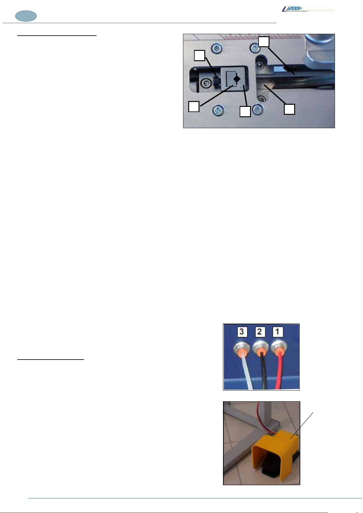
Pneumaticpedalhook-up
Beforeconnectingthemachinetothepneumaticsystem,youmust
rstconnectthecontrolpedal.
Thethreeairlineswhichareconnectedtothepedalassembly
mustbeinsertedinthethreeconnectorslocatedontheright-hand
sideofthemachineinthefollowingorder:
1) RED line in the connector on the outer side (1).
2) BLACK line in the intermediate connector (2).
3) TRANSPARENT line in operator side connector (3)

13
1
C
AB
A
TRANSLATION OF THE ORIGINAL INSTRUCTIONS (Keep for future reference)
Document Code Rev. Date saved Date printed
U200P INSTRUCTIONS 01 30/06/2016 30/06/2016 EN
Alignmentfencesunit
Thealignmentfencesunit,positionedontheworkingbench,can
slidealongtheassemblylineoftheringunitanditspositionis
adjustedbytheoperator.
Fixed fences for 120° and 135° corners may also be installed
inthe fence support (A) for making frames with 6 and 8 sides
respectively (available as optional accessories).
Two-knobfence(optional)
Thexedfencecanbereplacedwiththetwo-knobmodel(C)which
allowstheusertoadjustthetiltofthemouldingstopinrelation
totheworkbench.
Mouldingsmayhaveaslantingedgewhichwouldmaketheaction
ofthehorizontalclampineffective.Thetwo-knobfenceisdesigned
toincludetiltadjustmentofthesurfaceagainstwhichthemoulding
rests to improve stability.
The two-knob fence can be used to improve clamping of the
mouldingsduringassembly.

14
TRANSLATION OF THE ORIGINAL INSTRUCTIONS (Keep for future reference)
Document Code Rev. Date saved Date printed
U200P INSTRUCTIONS 01 30/06/2016 30/06/2016
EN
2. INSTALLATION
2.1. STORAGE
Themachine,intendedforindoorinstallationmustbestored,ifnecessary,inwellventilatedstoragefacilitiesandprotectedfromdust.
Thedeliveredelementsmustremainintheiroriginalpackinguntilthetimeofnalinstallation.
Allpartsofthemachinesubjecttotheriskofoxidationareprotectedwithgreaseandprotectivespraysatthetimeofdispatchtoprevent
oxidationcausedbyweatherconditions.
Inthecaseofprolongedinactivitythemachinemustbestoredwithallnecessaryprecautionstakenbasedonthelocationandexpected
storagetimes:
1. Store the machine in an enclosed place.
2. Protect the machine from impact and stress.
3. Protectthemachinefromhumidityandexcessivetemperaturedifferences(refertothetablebelow).
4. Donotallowcorrosivesubstancestocomeintocontactwiththemachine.
5. Checkthatthepackhasnotbeendamagedandthatitisperfectlydry.
6. Specically,ifthemachineisinsideashippingcontainer,thestoragearemustbecoveredandprotectedagainstdirectweather
includingrain,snowandhail,anditmustbeaccessibleexclusivelytoauthorizedpersonnel.
Themachineisprotectedinsuchawayastowithstandthetemperatures,humidityandvibrationlevelstypicallyassociatedwith
transportandstorage.
Ambient
temperature
Storing
temperature
Relative humidity
Vibrations
Atmospheric
pressure
-25/+40°C
-25/+55°C
0/+55°C
100%attemperatureof+25°C
Lowerthan50%attemperatureof+40°C
Lowerthan90%attemperatureof+20°C
5.9m/s2(0.6G)orhigher
900mbarorhigher
Avoidplaceswhere
there may be
unexpectedchangesin
temperature that could
lead to the formation
of condensate or
freezing.
Storagetemperatureisconstruedasashort-termvalue,e.g.duringtransportation.Condensationorfreezingnormallyoccursinsites
subjecttosignicanttemperatureexcursions.Evenifrelativehumidityinsuchconditionsfallswithinthevaluesshowninthetable,
locationssubjecttosignicanttemperaturechangesshouldbeavoided.
2.2. CHECKS ON RECEPTION
NOTES
It is essential to check the packs at the time of arrival and in the precise moment in which they are received. The check is performed
in two stages for each pack received to avoid misunderstandings with the shipping agent.
Administrativecheck
1. Crate number and number of packs.
2. Weightandsize
3. Correspondenceofinformationonshippingdocumentwiththematerialeffectivelydelivered(description,serialnumber,etc.).The
technicaldatagivenonthemachineidenticationplatemustcorrespondwiththedategiveninthetechnicaldatasupplied).
4. Checkcorrespondencebetweenshippingdocumentdataandtheorder.
Technicalcheck
1. Conditionandintactnessofpackaging.
2. Checkthatthepackagingshowsnosignsofvisibledamagecausedduringtransportandhandlingoperations.
Alltheabovechecksmustbeperformedbyinspectioninthepresenceoftheshippingagent’sdeliveryperson.Ifanydamageisnoted
orthesupplyisincompleteorincorrect,informthemanufacturer’ssalesdepartmentimmediately.
NOTES
In relation to the above prescriptions, the manufacturer informs the user that in compliance with current international and national
rulings, goods are always shipped at the risk and responsibility of the purchaser and, unless otherwise stated in writing at the
time of the order conrmation, freight travels without insurance cover.

15
A
B
C
TRANSLATION OF THE ORIGINAL INSTRUCTIONS (Keep for future reference)
Document Code Rev. Date saved Date printed
U200P INSTRUCTIONS 01 30/06/2016 30/06/2016 EN
2.3. TRANSPORT, LIFTING AND HANDLING
Dimensions,weightandhandlingofindividualmachineparts
BOX DIMENSIONS
Machineheight .............................................440mm-21⁄64in
Machine depth ............................................ 500mm-11⁄16in
Machinewidth.............................................660mm-63⁄64in
Weightofthemachine(includingthepackaging)approx.35kg-88lbs
DANGER – CAUTION
• Themachinemustbetransportedtoapositionasclosetotheintendedinstallationsiteaspossible.Saidsitemustbe
checkedbeforehandtoobtaininformationaboutthenecessaryclearancesanddimensions,includingtheessential
spacerequiredforinstallationprocedures.
• Itisstrictlyprohibitedtoliftloadsoverpeople.Ifpersonsarepresentinthearea,lowertheloadandensureeveryone
movesoutoftheway.
2.4. LIFTING AND HANDLING
The U200P machine is shipped ready for use.
Theboxdimensionsare:(660x440x500)mm.(seegure)
Transportmustbecarriedoutbyprofessionallyqualiedpersonnel.
Themachinemustbetransportedinsuchawayastoavoidany
damagetoitscomponents:
· The machine must be transported in its installation position.
· Beforetransportingthemachine,greaseallnon-paintedparts
to avoid the risk of deterioration.
· Based on the type of transport, take care to protect the machine
from all possible impact and stress.
NOTE – The machine must be lifted by TWO operators.
NOTE –It is advisable to keep the packaging in case it is
needed to store or transport the machine at a later date.
Themachineismovedonatwo-wheeltrolley.
MULTIPLE TRANSPORT AND HANDLING
Thetransportofmorethanonemachinecanbecarriedoutusing
aEUROPALLETwhichcancarryuptoamaximumof10boxes
(10 machines)
Overalldimensions=(80x120x180mm-AxBxC)

16
TRANSLATION OF THE ORIGINAL INSTRUCTIONS (Keep for future reference)
Document Code Rev. Date saved Date printed
U200P INSTRUCTIONS 01 30/06/2016 30/06/2016
EN
.2.5. REMOVING THE PACKAGING
Descriptionofthepackaging
The machine may be shipped in a container or on a lorry.
Inbothcasesthesametypeofpackingisenvisagedwhichissuitableforguaranteeingthegoodconditionandproperpreservation
ofthemachineduringtransportuptothetimeofdeliverytothecustomer.
Themachineisshippedpackedinaspecialboxandprotectedagainstdamagebypolystyreneinserts.
Maximumdimensions660x440x500(AxBxC).
NOTE –It is advisable to keep the packaging in case it is needed to store or transport the machine at a later date.
Whenstoringthemachine,neverstacktwomachinespackedonapalletwithshrinkwrap.
Thevariouspackingmaterialsmustbedisposedofincompliancewiththerelativelegislationinforce.Seekadvicefromthedelegated
authoritiesand/ortheassistanceofspecialistcompaniesauthorisedtodisposeofpollutantorrecyclablewasteproducts.
DANGER – CAUTION
Warning – pollution hazard: do not dispose of the packing material in the environment; retain it for future transport
uses or consign it to a recycling company.
Evaluation and management of the packing materials in terms of biological compatibility are the duty and responsibility
of the user.

17
TRANSLATION OF THE ORIGINAL INSTRUCTIONS (Keep for future reference)
Document Code Rev. Date saved Date printed
U200P INSTRUCTIONS 01 30/06/2016 30/06/2016 EN
3. PRELIMINARY PREPARATION AND ADJUSTMENT PROCEDURES
3.1. PUTTING THE MACHINE INTO SERVICE
1)POSITIONTHEMACHINEONTHETABLEORANOTHERHORIZONTALWORKSURFACE
2) CONNECT THE PEDAL BY INSERTING THE AIR LINES IN THEIR CONNECTORS ON THE SIDE OF THE MACHINE.
3) CONNECT THE COMPRESSED AIR SUPPLY LINE.
4) FIT THE VERTICAL CLAMP UNIT.
3.2. POSITIONING(IFOPTIONALSTANDHASBEENPURCHASED)
Suitabilityoftheoor–supportingsurface
The machine must be positioned on a solid, reinforced concrete foundation.
Theoormusthaveanadequateloadbearingcapacitytosupporttheweightofthemachine.Theoormustbedesignedandprepared
by the user.
Preparationonsite
Themachinelayoutisprovidedasanattachmenttothismanual.Itiscompletewiththenecessarydataforpositioningonthefactoryoor.
THEPLACEINWHICHTHEMACHINEISUSEDmustbecleanandfreeofobstacles(seegure).
TOALLOWFOREASYREMOVALOFTHEMACHINEFORMAINTENANCEitmustbepositionedinaplacehavingthesurface
dimensionsindicatedinthegure.

18
TRANSLATION OF THE ORIGINAL INSTRUCTIONS (Keep for future reference)
Document Code Rev. Date saved Date printed
U200P INSTRUCTIONS 01 30/06/2016 30/06/2016
EN
3.3. ASSEMBLY OF SEPARATELY SHIPPED UNITS
DANGER – CAUTION
All assembly activities concerning machine units supplied separately, include highly delicate operations which call
for signicant experience. Consequently they must be carried out exclusively by personnel appointed directly by the
manufacturer or authorised by the same and, in any case, under the manufacturer's responsibility. These activities are
therefore the sole responsibility of the machine manufacturer’s personnel.
Installationofworkingbenchextensions(optional)
Theworkingbenchextensionsareoptionalandmayberequestedfromthemanufacturer.
Theirinstallationrequiresprecisealignmentbetweentheworkingbenchandtheextensionssothatthelowersurfaceofthemouldings
restfullyontheentiresupportsurfacewhenthedoublestopperpressesdownontheendsofthemouldings.
Toinstalltheextensionsproceedasfollows:
1. Unscrewthegrubscrewslocatedontheleft-andright-handsidesofthemachine.
2. Placetherightandleftextensionsalongsidethemachineaccordingly.
3. Insertthexingscrewsandaligntheextensions.Finally,tightenthescrews.
Table of contents
Other FLETCHER Industrial Equipment manuals


Popular Industrial Equipment manuals by other brands

ABB
ABB HT592862 Operation manual

Siemens
Siemens 3KC3424-2AA22-0AA3 operating instructions

SCHUNK
SCHUNK PSK 22/1 Assembly and operating manual

Sartorius stedim
Sartorius stedim Sartoclear Pilot Filter Holder operating instructions

RK Rose+Krieger
RK Rose+Krieger LZ60 S/P Assembly instructions

Jäger
Jäger Z33-M060.11 K02S1 manual

Wire wizard
Wire wizard TORCH WIZARD Installation & operation manual

Arcflash Labs
Arcflash Labs SGP-34 user manual

Jäger
Jäger Z33-D060.02 K0,9a manual

SKF
SKF MonoFlex B Series Translation from the Original Operating and Maintenance Instructions

Festo
Festo GRLZ operating instructions

Omec
Omec SBM1200 manual


