8.
Note: The dew point of the air must be maintained below the
lowest ambient temperature to which the double interlock
system piping will be exposed. Introduction of moisture into
the system piping that is exposed to freezing temperatures
can create ice blockage, which could prevent proper opera-
tion of the system. As minimum the supply of air should be
taken from refrigerated area at the lowest temperature. The air
supply system must be carefully designed to prevent plug-
ging by frost deposits. Special requirements such as those in
FME&R’S “Installation Guidelines for Refrigerated Storage”
may need to be incorporated.
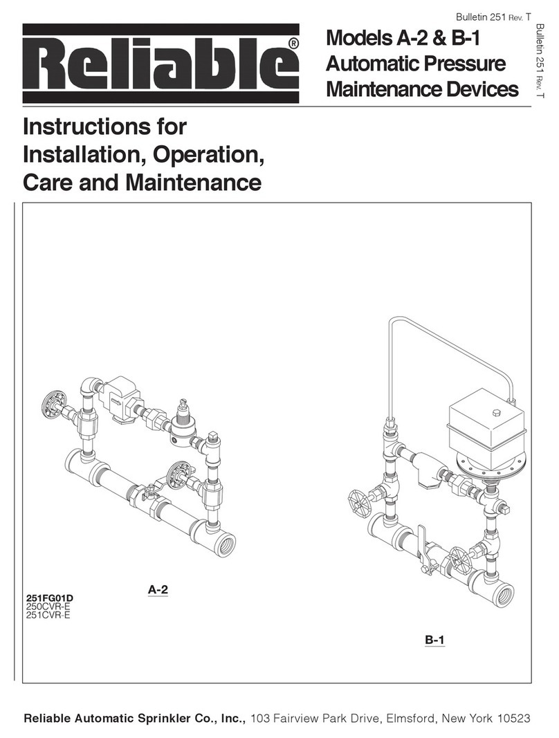
Whenever multiple Preaction Systems are installed at
the same location, it is strongly recomended that each
system have its own Model A-2 Pressure Maintenance
Device for individual maintenance of air pressure.
System Electrical Requirements
All releasing and detection devices in Type D Double
Interlock Preaction Systems are operated and supervised
by the Potter PFC-4410-RC Releasing/Control Panel in
accordance to the wiring diagram shown in fig. 4. The Re-
leasing/Control Panel should be set to use Program #11
(see Potter Instruction Manual #5403550).
The power supply, the standby emergency power
supply, battery charger, and the rectifier circuitry are
all contained within the Potter PFC-440-RC Releas-
ing/Control Panel. Batteries that provide ninety hours
of standby power are required for FM Approved sys-
tems.
The Model BNG-1 Manual Emergency Station can
be connected as a simple detector for fire annuncia-
tion, or the Model BNG-1F can be connected to both
zones for total system emergency manual operation.
The solenoid valve is operated and supervised by
the Potter PFC-4410-RC Releasing/Control Panel. The
Potter PFC-4410-RC Releasing/Control Panel requires
120 VAC.
Caution: Repairs or disassembly of the solenoid
valve should only be done by a trained technician. An
improperly repaired or partially assembled solenoid
valve could result in failure of the valve to operate.
Double Interlock Preaction System
Electric/Electric Actuation (Type D)
Engineering Specifications
General Description
Preaction system shall be a double interlock preaction
system utilizing a 2” (50mm), 212” (65mm), 3" (80mm) and
76mm Reliable Model DDX Deluge Valve. Deluge Valve
shall be a [2” (50mm)] [212” (65mm)] [3” (80mm)] [76mm]
[cULus Listed] [Factory Mutual Approved] hydraulically
operated, differential latching clapper-type valve. Deluge
valve construction shall be of lightweight, ductile-iron con-
struction with “screw in” stainless steel seat and clapper
assembly. Stainless steel seat shall have O-ring seals to
resist leakage and corrosion. Clapper facing shall be
pressure actuated, providing a limited compression seat
for the sealing force between the clapper rubber facing
and the valve seat. Deluge valve shall have an external re-
set knob for resetting the clapper without requiring the re-
moval of the valve face plate. Push-rod chamber design
shall consist of a stainless steel piston/ push-rod and
spring assembly with diaphragm seal secured to the
casting through a push-rod guide constructed of a syn-
thetic engineering plastic to resist corrosion. Casting shall
have a bleeder hole located on the pushrod chamber for
air/water leakage indication. Trip ratio shall be approxi-
mately a 3:1 force differential. Deluge valve shall be of the
straight through design to minimize friction loss. Deluge
valve shall be activated by [hydraulic wet-pilot][low pres-
sure, pneumatic dry-pilot][electric] actuation trim. Inlet re-
striction orifice shall be factory installed into the inlet port of
the deluge valve push-rod cover plate and not be a sepa-
rate part of the deluge valve trim. End connection style to
be [2” (50mm), 2½” (65mm), 3” (80mm) or 76mm]
grooved inlet and grooved outlet, per ANSI/AWWA C606.
Deluge valve shall have a rated working pressure of 250
psi (17,2 bar) and shall be factory hydrostatic tested at
500 psi (34,5 bar). Deluge valve to be [2” (50mm)][2½”
(65mm)][3” (80mm)][76mm] Reliable Model DDX Deluge
Valve (Bulletin 513).
Valve trim shall be Type D electric/electric release trim
consisting of the following components:
•Hydraulic trim shall be galvanized and brass com-
ponents specifically Listed/Approved with the de-
luge valve, including associated pressure gauges,
1¼” drain connection, alarm device, alarm test, and
push-rod chamber connections.
•Electrical two-way, normally-closed, pilot-operated
solenoid valve [cULus Listed] [FM Approved] for its
intended use. The solenoid valve shall be con-
structed of a brass body with stainless steel sleeve
tube, springs, stop and plunger, and with ½” female
NPT end connections. Solenoid valve shall have a
maximum working pressure of [175 psi (12,1 bar)]
[250 psi (17,2 bar)] and maximum ambient temper-
ature rating of 150°F (66°C). Power consumption of
integrated coil shall be limited to [10watts (175 psi
(12,1 bar) Rated] [22 watts (250 psi (17,2 bar)
Rated] and require 24 VDC from a releasing/control
panel listed for such service. Solenoid valve shall be
a Skinner ½” normally-closed solenoid valve,
[Model 73218BN4UNLVNOC111C2 (175 psi (12,1
bar) Rated] [Model 73212BN4TNLVNOC322C2
(250 psi (17,2 bar) Rated].
•Low air pressure switch to indicate loss of air pres-
sure in system piping. Pressure switch shall be
[cULus Listed] [FM Approved] and of the bel-
lows-activated type enclosed in a weatherproof, 4x,
NEMA 4-rated enclosure incorporating tamper-re-
sistant screws. There shall be two sets of SPDT
(Form C) contacts rated at 10.0 A @ 125/250 VAC
and 2.5 A @ 6/12/24 VDC. The pressure switch shall
have a maximum service pressure rating of 250 psi
(17,2 bar) and shall be factory adjusted to operate at
apressureof4to8psi(0,27to0,55bar)withadjust
-
ment up to 20 psi (1,3 bar). Switch shall be provided
with a ½” NPT male pressure connection. Low air
alarm pressure switch shall be System Sensor
EPS10-2.
•Pressure maintenance device for maintaining a
constant system pneumatic pressure regardless of
pressure fluctuations in the compressed air (or nitro-
gen) source. The pressure maintenance device
shall consist of galvanized trim and brass parts, in-
cluding a strainer, a field adjustable air pressure
regulator, and associated pressure gauge. The
pressure regulator shall have an adjustable outlet
