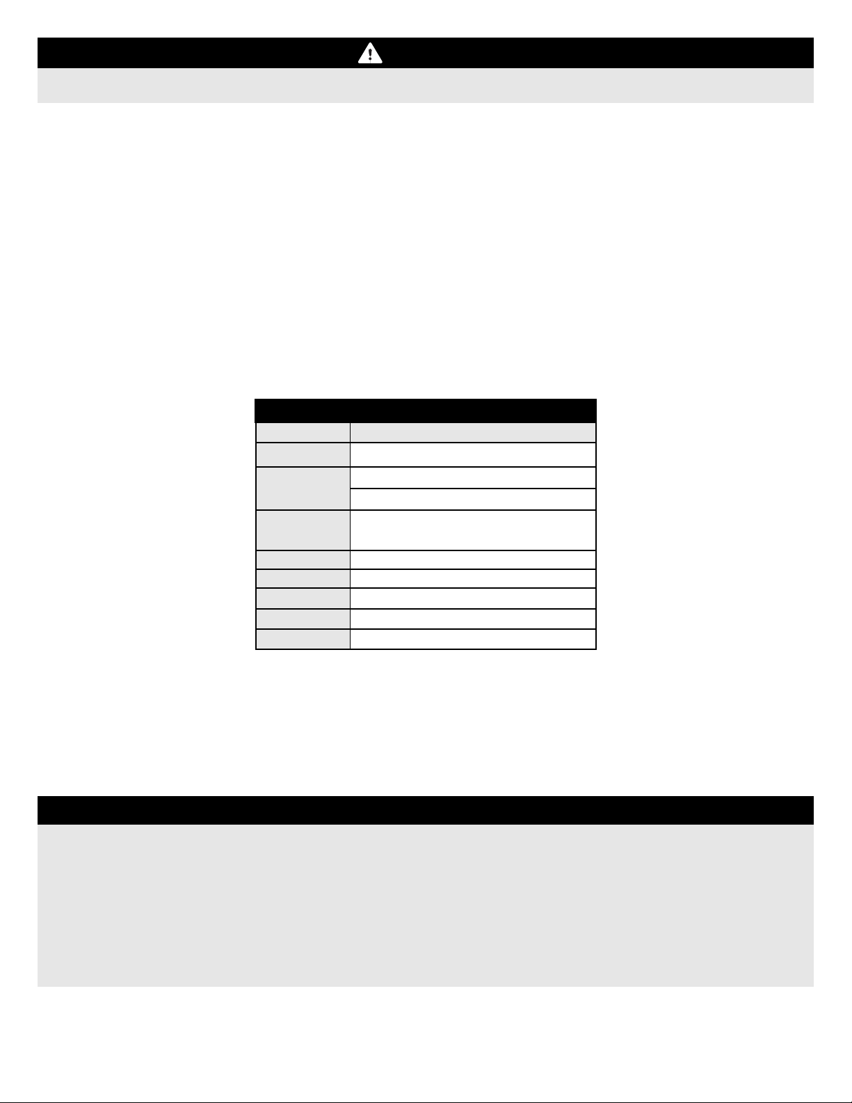
Flex FLEXJET TV SUPER PNP User manual

TV


The FlexJet TV is designed to be a high-performance, 3D-capable (post-stall manuevering) EDF. It is
capable of aerobatics and 3D manuevers such as hovers, flat-spins, pin-wheels, tumbles, and more!
To achieve this manuevering capability, The FlexJet TV has approximately 90% more power than the
original FlexJet while remaining very light. This excess power is intended for uplines and 3D manuevers
only. Because of this, the pilot is required to limit the speed of the aircraft, and the G-Load on the Aircraft.
- Powered dives are not permitted
- Extended level flight at full throttle is not permitted
- High-Speed, High-G manuevers are not permitted
- Limited to maximum of 20MPH (32km/h) of wind speed or gust
Over-speeding or over-stressing the aircraft can result in structural failure and a crash, which may also
cause personal injury and/or property damage.
1
NOTICE
DAMAGED PRODUCT(S), INJURY AND/OR PROPERTY DAMAGE CAUSED BY FAILURE TO
FOLLOW THE ABOVE GUIDELINES IS NOT COVERED UNDER WARRANTY.
If you as the Purchaser or user are not prepared to accept the liabity associated with the use of the Product, you are
advised to return this product immediately in new and unused condition to the place of purchase. In the event you wish to
return this product, as the Purchaser or user, you are responsible for return shipping.
For more information regarding returns please visit:
https://www.flexinnovations.com/returns.asp
1

2
BEFORE CONTINUING WITH THIS INSTRUCTION MANUAL OR ASSEMBLY
OF YOUR AIRCRAFT, PLEASE VISIT OUR WIKI SUPPORT SITE FOR THE
LATEST PRODUCT UPDATES, FEATURE CHANGES, MANUAL ADDENDUMS
AND FIRMWARE CHANGES FOR BOTH YOUR AIRCRAFT AND THE
INSTALLED AURA 8 ADVANCED FLIGHT CONTROL SYSTEM.
wiki.flexinnovations.com/wiki/FlexJetTV
wiki.flexinnovations.com/wiki/Aura

3
BOX CONTENTS
TABLE OF CONTENTS
INTRODUCTION
On behalf of Flex Innovaons, thank you for purchasing
the FlexJet TV!
The FlexJet TV combines a proven plaorm of modern aerodynamics with
sport jet praccality and performance with an 8s Power System with a thrust
vectoring nozzle for added capability in post-stall ight.
Trailing link landing gear, and the wing's wide angle of aack range, along
with Aura 8 make takeos and landings easy. Aerobacs are eortless and
impressive. The FlexJet TV excels at harriers, hovers, at-spins, tumbles,
unlimited vercal maneuvers, and high alpha manuevers.
For the latest updates, features, addendums and more, before assembly,
please visit:
hp://wiki.exinnovaons.com/wiki/FlexJetTV
Airframe Advisory
Wiki Advisory
Introduction
Box Contents
Specifications
Replacement Parts
Optional Accessories
Completion Items
Battery Charging Guidelines
Special Language Definitions
Important Information Regarding Warranty
Safety Warnings and Precautions
Low Voltage Cutoff
Aura 8 AFCS
Transmitter Setup
Reciever insatllation/Aura Setup Note
Connecting a Battery/Arm ESC
Reciever Installation/Servo Connections
Retracts/Gear Sequencer Operation
EDF Access Hatch, Tail Pipe, Exhaust Nozzle Removal
Flying Stabilizer Installation
Wing Installation
Battery Installation
Vertical Stabilizer Installation
EDF Access Hatch, Tail Pipe, Exhaust Nozzle Re-installation
Thrust Vector Nozzle Setup
Missile Rail Installation
Transmitter Control Test
Flight Control Sensor Test
Center of Gravity
Pre-Flight Checks
Flying your FlexJet TV
Advanced FlexJet TV Aura Configuration
Airframe Repairs
Replacing Servos
Servicing the Power System
Aircraft Troubleshooting Guide
Limited Warranty
AMA Safety Code
Elevator Trim Gauges
1
2
3
3
4
4
4
4
4
5
5
5
5
6
7
8
8
9, 10
10
11
...............................................................
......................................................................
.........................................................................
......................................................................
.....................................................................
.............................................................
.........................................................
...............................................................
..............................................
............................................
........................
......................................
.............................................................
......................................................................
...............................................................
..............................
.........................................
..........................
....................................
....
.......................................................
.........................................................................
.....................................................................
.....................................................
...
.......................................................
...............................................................
............................................................
.........................................................
........................................................................
......................................................................
................................................................
..................................
........................................................................
.......................................................................
......................................................
..................................................
........................................................................
......................................................................
................................................................
12, 13
14
15
15, 16
17
18
18
19
20
21
21
22
23
24
25
25
26
27
28
29
Custom-tuned Aura 8 gyro stabilizaon system provides
the ulmate in stability and control
Powerful 80-sized in-runner motor provides ecent
power
120amp 8s ESC provides reliable power
11-bladed 90mm fan for outstanding thrust and sound
Electric retracts with metal pivot
High deecon thrust vector nozzle gives unparraelled
control in post-stall ight.
Electric gear doors with sequencer installed
Embedded carbon ber spars in wings and stabilizer
Custom-designed control horns to opmize control
geometry and performance
High-precision digital servos with metal gears
Lightweight EPO foam is s and tough

COMPLETION ITEMS
Potenza 80-DF BL 1500 Kv
Brushless In-runner Motor
(FPZM1080DFA)
Potenza DS15 Digital Servos (QTY: 7)
(FPZDS15B)
Aura 8 Advanced Flight Control
System (FPZAURA08ZZFTV)
90mm EDF Fan Assembly
(FPMDF90A)
3500-4200mAh 8S 29.6V 40C+ Li-Po
(8S 4000mAh 70C: FPZB40008S75)
NEEDED TO
COMPLETE
INSTALLED!
INSTALLED!
SPECIFICATIONS
41.6 in. (1056mm)
55.1 in. (1400mm)
Standard: 7.1lb (3220g)
RTF with 8S 4000mAh ba�ery installed
(QTY:2 Required for
JR DMSS Mode B)
(Recomended
Spektrum Receiver)
(Recomended
FASSTest Receiver)
(QTY:2 Required
to make 8S pack )
(Not compatible
with 8S Li-Po)
BATTERY CHARGING GUIDELINES
The assembly of the FlexJet TV can be accomplished in 1-2 hours.
Prior to assembling the airplane, it is advisable to charge your
battery so that you are ready to begin setup upon completion of the
assembly of your model.
We recommend the use of an advanced Li-Po balancing charger
capable of 8S. A 4S charger can be subistuted if using QTY:2 4S
Li-Po's in series.
The FlexJet TV was designed around the Potenza Li-Po Hyper
Series 8s 4000mAh 75C Li-Po battery (FPZB40008S75) or QTY:2
Potenza Li-Po Hyper Series 4s 4000mAh 75C Li-Po batteries
(FPZB40004S75) in series. In our extensive testing and
development of the FlexJet TV, these batteries provided the best
combination of power, weight, and flight time. In addition, these
batteries feature an EC5 connector, so no soldering is required for
use in your FlexJet TV.
Potenza Li-Po batteries are available at www.flexinnovations.com
WARNING
FOLLOW ALL INSTRUCTIONS PROVIDED BY YOUR
BATTERY AND CHARGER MANUFACTURER.
FAILURE TO COMPLY CAN RESULT IN FIRE.
OPTIONAL ACCESSORIES
INSTALLED!
INSTALLED!
REPLACEMENT PARTS
4
FPZB40008S75
FPZB40004S75
FPZA1026
FPZA1010
SPMAR8010T
FUTR7008
FUTR2008
FPZA1012
ISDTD2
Potenza 8S 4000mAh 75C Li-Po
Potenza 4S 4000mAh 75C Li-Po
Potenza EC5 Series Connector
Potenza Digital Battery Analyzer
Spektrum AR8010T Reciever
Futaba R7008SB Reciever
Futaba R2008SB Reciever
Potenza 2" Y-Harness
iSDT D2 Smart AC Charger 100w x2 6s
Receiver
NEEDED TO
COMPLETE
6CH + MODERN DIGITAL
CONNECTION: SRXL, Futaba or
Hitec S.Bus, Graupner HOTT, Jeti
UDI, JR DMSS XBus
NEEDED TO
COMPLETE
INSTALLED!
Potenza DS12 Digital Servos (QTY: 4)
(FPZDS12 / FPZDS12R)
FlexJet TV Fuselage Orange (No Hatches)
FlexJet TV Canopy and Fan Hatch Orange
FlexJet TV Nose Cone / Tail Pipe Orange
FlexJet TV Pushrod Set
FlexJet TV Light Weight Wire Strut Set
FlexJet TV Light Weight Foam Wheel Set
FlexJet TV Fwd. Wing Skin Reinforcement
FlexJet TV Thrust Vectoring Nozzle
L+R Wing Set Orange
L+R Stab and Fin Set Orange
Ventral Fin and Missle Rail Set Orange
Wing + Fin Carbon Fiber Tube Set
Orange Decal Set
Pushrod Set
Hardware Package
Landing Gear Struts
Landing Gear Rubber Strut Downstop Set
Wheel Set
Doors, Hinges, Misc. Plastic Parts
Metal Clevis Set (4)
90mm EDF Fan Assembly (No Motor)
Potenza 3-Piece Retract Set
Potenza Electric Retract (single)
Potenza Gear/Door Sequencer
Potenza DS15 Servo Arm and Screws Kit
Potenza DS15 MG Digital Servo w/165mm
Potenza DS12 MG Sub-Micro Servo
Potenza DS12 MG Sub-Micro Reverse Servo
V-Good 120 HV ESC
HobbyWing 120 HV ESC
Aura 8 AFCS for FlexJet TV
Potenza 80 1500KV EDF Inrunner Motor
INSTALLED!
(FPZEDFHW120BEC)
HobbyWing 120 HV ESC
V-Good 120 HV ESC
OR
(FPZEDFVG8S120BEC)
(Recomended
S-FHSS Receiver)
OPTIONAL ACCESSORIES (CON'T)
ISDTT8
iSDT T8 Smart DC Battery Charger 1000w 8S
6+ Channel Computer Transmitter
6+ Ch. Receiver with 6-output ports and
Modern Digital Connection
WITH
FPM344001
FPM344007
FPM344014
FPM344015
FPM347018
FPM347019
FPM347020
FPMADFTV90
FPM347003
FPM347005
FPM347009
FPM347011
FPM347012
FPM347015
FPM347016
FPM347017
FPM347018
FPM347019
FPM347020
FPMA0004
FPMDF90A
FPZA1020
FPZA1020S
FPZA1021
FPZA1023
FPZDS15B
FPZDS12
FPZDS12R
FPZM180DFA
FPZAURA08ZZFJTV
FPZEDFHW120BEC
FPZEDFVG120BEC

The following terms are used throughout the product literature to indicate various levels of potential harm when operating this product:
SPECIAL LANGUAGE DEFINITIONS
ATTENTION
WARNING
AGES 14+
NOTICE:
CAUTION:
WARNING:
Procedures, which if not properly followed, create a possibility of physical
property damage AND a little or no possibility of injury.
Procedures, which if not properly followed, create the probability of physical
property damage AND a possibility of serious injury.
Procedures, which if not properly followed, create the probability of property
damage, collateral damage, and serious injury OR create a high probability of
serious injury.
Read the ENTIRE instruction manual to become familiar with the features of the
product before operating. Failure to assemble or operate the product correctly can
result in damage to the product, personal property, and cause serious or fatal injury.
All instructions, warranties and other collateral documents are subject to change at
the sole discretion of Flex Innovations, LLC. For up-to-date product literature, please
visit our website at www.flexinnovations.com, click on your aircraft and the Aura 8
AFCS product pages.
This product is not intended for
use by children under 14 years
without direct adult supervision.
IMPORTANT INFORMATION REGARDING WARRANTY
SAFETY WARNINGS AND PRECAUTIONS
Please read our Warranty and Liability Limitations section before building this product. If you as the Purchaser or user are not
prepared to accept the liability associated with the use of this Product, you are advised to return this product immediately in
new and unused condition to the place of purchase.
LOW VOLTAGE CUTOFF
Protect yourself and others by following these basic safety guidelines.
1. This manual contains instructions for safety, operation and maintenance. It is essential to read and follow all the
instructions and warnings in the manual, prior to assembly, setup or use, in order to operate correctly and avoid damage or
serious injury.
2. This model is not a toy, rather it is a sophisticated hobby product and must be operated with caution and common sense.
This product requires some basic mechanical ability. Failure to operate this product in a safe and responsible manner could
result in injury or damage to the product or other property.
3. This model must be assembled according to these instructions. Do not alter or modify the model outside of these
instructions provided by Flex Innovations, Inc. as doing so may render it unsafe and/or unflyable. It is your responsibility to
ensure the airworthiness of the model.
4. Inspect and check operation of the model and all its components before every flight.
5. If you are not an experienced pilot or have not flown a high-performance model before, it is recommended that you seek
assistance from an experienced pilot in your R/C club for your first flights. If you're not a member of a club, the Academy of
Model Aeronautics (AMA) has information about clubs in your area whose membership includes experienced pilots.
6. Keep the propeller area clear from such items as loose clothing, jewelry, long hair, or tools as they can become entangled.
Keep your hands and body parts away from the propeller as injury can occur.
7. Never fly in visible moisture, or submerge the airplane or any of its electronic components in water. Permanent damage to
electronic components may occur, or corrosion of components may lead to intermittent failures.
Li-Po batteries have a nominal (rated) voltage of 3.7V per cell, and fully charged, reach 4.2V per cell. Batteries are designed to be
discharged below the nominal voltage, however, if they are discharged below 3.0V per cell, damage will occur and the pack will lose
capacity. For best long term battery life, set a timer and land after a time that leaves approximately 15% of the battery's capacity
remaining.
Low voltage cutoff is a feature that is built into the included ESC that is designed to protect the connected battery from being
discharged too far and causing permanent damage to the cells. Circuitry within the ESC will automatically detect when the input
voltage from the battery pack reaches below 3.15V per cell (average) and will remove power to the motor, but still deliver power to
the servos so that a safe landing may be made. If the motor begins to lose power rapidly during flight, the LVC has sensed that the
total voltage of the pack has dropped below 3.15V per cell average, and the airplane should be landed immediately.
5

6
AURA 8 AFCS
Works conveniently with all major radio systems
Accepts signals from Spektrum SRXL, Futaba S.Bus,
Graupner Hott (Sum D of 8), JR XBus (Mode B), Jeti UDI12
(standard), Hitec S.Bus, PPM Stream
Expertly tuned and ready to use
USB port allows loading model configurations, user
programming, and firmware updates (cable included)
Flexible and extensive programming through Windows-
based PC or tablet
3+ flight modes allow precise or aggressive settings to be
selected in flight
3-axis gyro utilized in FlexJet TV programming
Powerful 32-bit processor and multi-axis sensor for future
updates.
The Aura 8 Advanced Flight Control System (AFCS) installed in
your FlexJet TV is a giant leap forward in aircraft flight control
system technology. Compatible with virtually every receiver on the
market today, the Aura features special configuration for serial data
connection for Futaba or Hitec S.Bus, Spektrum SRXL, Graupner
HOTT (Sum D of 8), JR XBus (Mode B), and Jeti UDI12 (standard)
systems.
The Aura 8 advanced flight control system installed in your aircraft
has been pre-tuned for ease of use, eliminating many hours of
tedious setup. For the latest Aura features, programs, transmitter
downloads, and instructions, please visit wiki.flexinnovations.com/
wiki/Aura
The Aura is programmable through any Windows based PC or
tablet. All dual rate, expo, travel and assignable mode programs are
adjusted inside the Aura through the PC application. An assignable
master gain that is OFF by default can be enabled by the Aura
application. If desired, assign CH 8/AUX 3 on a proportional dial or
slider.
By default, CH6/Aux1 is used to select the 3 flight modes by 3
position transmitter switch. CH5/Gear is used to retract/deploy
the landing gear. Visit wiki.flexinnovations.com/wiki/Aura for the
latest Aura-related product information and
tips for your particular radio brand.
Description of Pre-Loaded Aura Flight Modes (FM)
Each of the modes has been tuned by the Flex Team to offer a solid start. Because tastes in control feel are unique, if changes in rates
and expo are needed, adjustments should be made through the Aura 8, not the transmitter..
Changes in gain value can only be made through the Aura or via master gain (if activated).
Flight Mode 1 (Test / Safety):
Gyro gain is set to off. All rates are set to low for general flight. Exponential is tuned for comfortable flight. Tailerons are active. Thrust
Vectoring is deactivated.
Flight Mode 2 (Sport / Precision):
Gyro gain is set to low. All rates are set to low for sport / precision flight. Exponential is tuned for comfortable flight. Tailerons are active.
Thrust Vectoring is active and set to moderate rates.
Mode 3 (3D Rate):
Gyro gains are high and tuned for low-speed post-stall flight. All rates are set to highest. Exponential is tuned for comfortable flight.
Tailerons are active. Thrust Vectoring is active and set to high rates. Do NOT fly at High Speed. Doing so may induce gyro
osciliations!!

TRANSMITTER SETUP
The Aura 8 AFCS is designed to work seamlessly with all major transmitter and receiver brands. When programming your transmitter, start
with a freshly reset new model memory in your transmitter. Make ONLY the changes shown in the Transmitter Configuration Guide
unless otherwise noted.
The Aura 8 in your FlexJet TV defaults to 3 flight modes that are switched via CH6/Aux1 in your transmitter. You may need to reassign
CH6/Aux to a 3-position switch.
The retracts in the FlexJet TV are operated via CH5/Gear in your transmitter. You may need to reassign that CH5/Gear in your transmitter to
a 2-position switch.
Consult your transmitter manual if you have questions on how to change the switch or channel assignments.
The Aura comes pre-programmed with dual rates and expos specifically designed for your aircraft. For large (greater than 5%) changes in
expo or dual rates, it is highly recommended to reset all expos and rates to default in the transmitter, and tune through the Aura Config Tool.
The Aura Config Tool is free to download, and can be used on any Windows-based PC or tablet. Download at:
www.flexinnovations.com/AuraConfigTool
7
JR transmitter users that use Spektrum DSM2/DSMX receivers should follow the Spektrum information in the chart
above.
If you are using a Futaba transmitter, please note that some Futaba transmitters have the throttle set to reversed by
default. Leave reversing set to defaults to start, and reverse as needed.
This aircraft can fly anywhere between 2:30 and 4 minutes (w/8S 4000mAh Li-Po), depending on flying style.
1.
2.
3.
NOTICE
FOR CUSTOMERS USING TRANSMITTERS OTHER THAN WHAT IS LISTED IN THE CHART ABOVE, PLEASE VISIT
OUR WIKI PAGE FOR INSTRUCTIONS SPECIFIC TO YOUR TRANSMITTER AND RECEIVER BRAND
JETI
HITEC
FRSKY
wiki.flexinnovations.com/wiki/Aura/JetiUse
wiki.flexinnovations.com/wiki/Aura/HitecSbusUse
wiki.flexinnovations.com/wiki/Aura/FrSkyUse
TRANSMITTER CONFIGURATION GUIDE
End Points
(Travel Adjust
or ATV)
Ail/Ele/Rud/Gear
Throttle
125%
100%
Sub Trim
Verify at zero, NOT ALLOWED
Trim Levers
Verify at zero
CH.5 (Gear) Assigned to a 2-position switch
Reversing None Required
Timer
Wing/Tail Type
1-Aileron, 1-Elevator, 1-Rudder (No Flaps)
CH.6 (FM)
Spektrum, Futaba & Graupner
Set to 2:10 for initial flights
Assigned to a 3-position switch
1
2
3
JR DMSS wiki.flexinnovations.com/wiki/Aura/JRUse
During radio setup ensure motor is disengaged by unplugging all wire leads that connect the ESC to the motor.
CAUTION

CONNECTING A BATTERY/ARMING THE ESC
1.
2.
3.
4.
8
Lower the throttle stick and trim to their lowest setting and turn
on the transmitter. Wait for your transmitter to indicate the radio
signal is being broadcast before proceeding.
Ensure the aileron, elevator and rudder gimbals are centered.
With the airplane on a solid surface, connect the battery to the
ESC and wait. The ESC will make the motor emit a series of
audible tones during its intialization process.
The ESC will make the motor emit a short, final tone sequence
idicating that the ESC is now armed, and the motor will spin in
response to throttle stick movement.
If a battery is connected to the ESC with the throttle fully
open on the active transmitter, the ESC will enter
programming mode. If this occurs, simply disconnect the
battery, lower the throttle, and reconnect the battery.
WARNING
When making adjustments to linkages,
transmitter settings or the Aura 8 flight control
system, disengage motor by unplugging from
ESC to guard against accidental spool up.
Hold the aircraft securely when connecting the
battery before flight. Always ensure any and all
objects are clear of the duct inlets and EDF fan
unit as they may become entangled.
WARNING
Always connect the battery when the throttle stick
and throttle trim is in the idle/cut-off position.
CAUTION
RECEIVER INSTALLATION / AURA 8 INSTALLATION NOTE
Throughout the assembly process, we will ask you to power up the radio system. In order to assemble your FlexJet TV properly, It is critical
that the receiver is bound to your transmitter and is communicating with Aura 8. Please do not proceed until the Aura 8 emits a solid
green LED (Aura received valid signal from reciever) and solid orange LED (Aura has power and calibrated sensor) when powered
up. Please note, for all systems EXCEPT JR DMSS MODE B, you can temporarily plug a servo into the reciever's aileron port to verify that
your receiver is bound to your transmitter. In the event that you are having difficulties with radio or Aura 8 installation please see the
following:
For issues with your transmitter and/or reciever, please review your transmitter/receiver manual or contact the manufacturer directly.
For issues regarding Aura 8 please reference the following:
• Wiki page: wiki.flexinnovations.com/wiki/Aura
• Contact Aura Support at 866-310-3539
While assembling the FlexJet TV, ensure motor is disengaged by unplugging all wire leads that connect the ESC to the motor.
CAUTION
Observe the following procedures to safely power up your model
after it has been bound. Ensure the motor is unplugged from
ESC unless sequence is followed to power up before flight.

RECEIVER INSTALLATION/SERVO CONNECTIONS
DEFAULT AURA CONNECTIONS
S1
S2
S3
S4
S5
S6
S7
S8
B
Left Aileron
Right Aileron
Left Elevator
Right Elevator
Rudder
Nosewheel steering
Left Thrust Vectoring
Right Thrust Vectoring
Rx Digital Connection
Aura will auto-detect modern digital receiver connection(s). Using a
modern digital receiver connection gives the Aura access to precise
data of each channel for additional gyro-enabled outputs, simplifies
wiring, and allows for more advanced features. To connect a
modern digital receiver connection, follow the steps on this page.
Supported Modern Data-Linked Receivers
Connecting Your Receiver to Aura
Aura will auto-detect these modern digital receiver connections:
Futaba or Hitec S.Bus
Graupner HOTT (Sum D of 8)
Spektrum SRXL
JR XBus (Mode B)
Jeti UDI12 (standard)*
A PPM (8CH, negative shift, approximately 22ms/frame) receiver may also be
connected into Port 'B', however Aura will not auto-detect and setup must be
performed through the Aura Config Tool (Windows Application).
9
For specific information on receiver types and our
recommended receivers for this aircraft, please visit the
FlexJet TV Wiki page at the below URL:
wiki.flexinnovations.com/wiki/FlexJetTV
Digital Receiver Connections
Note: If you are using Futaba S.Bus, be sure to use the proper
S.Bus port in your receiver. DO NOT use the S.Bus 2 port, as it
is not supported for use with the Aura 8. Refer to your
manufacturer's instructions for proper S.Bus use.
Note: When using Spektrum SRXL to connect to the Aura,
always connect the remote receivers to the Spektrum receiver,
NOT to the Aura.
While Spektrum usually outputs its digital data stream, it may
be necessary for Futaba, JR DMSS, Graupner HOTT, and Jeti
users to program the transmitter/receiver to output the correct
digital format listed on the previous page. Consult your
transmitter and receiver manuals for further details.
Bind your transmitter and receiver per your manufacturer's
instructions.
Connect the included male to male servo extension to the
receiver's data port (ex: S.Bus, SRXL etc.) and connect to servo
port 'B' on the face of the Aura. Refer to your radio
manufacturer's instructions for specific information on
appropriate serial port connections and system settings.
With the transmitter powered, power up the aircraft. Aura will
search (sweeping LEDs) and lock onto the signal. You will then
see solid orange (power and calibrated sensor) plus solid green
(valid radio source), and have control of the model.
Mount your receiver using double sided foam tape or hook and
loop tape. Consult your receiver manual for proper mounting.
1.
2.
3.
4.
A working throttle port and Retract port on the receiver is
REQUIRED.
Consult your receiver and/or transmitter instruction manual for
specific details on your radio system.
Examples of Recommended Receivers:
Spektrum SRXL
AR8010T
AR9030T
Jeti UDI
EX R6i
EX R11
JR DMSS
712BX
731BX
FrSky S.Bus
RX6R
RX8R
Futaba S.Bus
S-FHSS - R2008SB
T-FHSS - R7008SB
FASST - R6208SB
FASSTest - R7008SB
Graupner SUMD
GR-16L
Hitec S.Bus
Optima SL-8
**R7008SB must be set to Channel Mode B per R7008SB Manual**
ESC
-+
-+
ESC
Gear
Door
Sequencer
CH5/Gear
To
Electric Retracts
Gear/Door Servos
Gear
Door
Sequencer
CH5/Gear
To
Electric Retracts
Gear/Door Servos
Thro
Thro
Thro
Gear
Gear
SRXL
SRXL
SRXL
S.BUS
S.BUS
S.BUS
Thro
Thro
Gear
Gear
** Arrows indicate signal (data) flow. They do not necessarily indicate voltage (+) flow.
* Arrows indicate signal (data) flow. They do not necessarily indicate voltage (+) flow.

10
RECEIVER INSTALLATION/SERVO CONNECTIONS (CONTINUED)
NOTICE
Due to the servo port requirements, PWM is NOT SUPPORTED for the FlexJet TV.
PPM users should consult the Wiki Page
wiki.flexinnovations.com/FlexJetTV
RETRACTS AND GEAR SEQUENCER OPERATION
The following steps will be required EACH time the aircraft
is powered for flight:
Ensure your radio has Ch5/gear assigned to a 2-position switch.
Hold the FlexJet in a manner that the gear doors and retracts
are unobstructed and free to close and open.
Cycle your transmitters Ch5/Gear switch from down to up,
then down again waiting about 1 second in each position.
The gear sequencer is now armed and the gear will deploy or
retract.
Test the retracts. Ensure the gear/doors open and close without
binding or stalling the servos. Adjust ball links as necessary.
When satisfied with the result, power off the aircraft.
Please note, Ch5/Gear can be reversed in the transmitter for
user preference.
1.
2.
3.
4.
NOTICE
Due to the need of 10-servo ports for optimal performance, Spektrum Remote Receivers are NOT
SUPPORTED for the FlexJet TV.
A Receiver with a Modern Digital Connection AND working servo ports is the preferred receiver connection
method for the FlexJet TV.

Remove the two M3x10 Phillips washer head self-tapping screws that secure the EDF access hatch to the fuselage. Unplug both thrust
vectoring servos located on the EDF access hatch. Remove the screws that secure the thrust vectoring nozzle pushrods to the servo
arm. Remove the EDF access hatch and place the hatch and screws in a secure location to be used at a later step in the assembly
process.
Remove the two M3x25 Phillips self-tapping screws that secure the thrust vectoring nozzle to the fuselage. Remove the thrust vectoring
nozzle and place the TV nozzle and screws in a secure location to be used at a later step in the assembly process.
Using a #11 hobby knife, cut the piece of tape that secures the thrust tube to the EDF fan housing and remove the tape from the ducted
fan housing and thrust tube. Be careful to only cut the tape. Do not cut through the thrust tube.
Slide the tail pipe rearward until it is no longer connected to the ducted fan housing.
Carefully collapse the tail pipe (without creasing) and slide the tail pipe out the rear of the fusleage.
Please note, a video of the EDF access hatch, tail pipe, and exhaust nozzle installation/reinstallation is available at
http://wiki.flexinnovations.com/wiki/FlexJet.
11
EDF ACCESS HATCH, TAIL PIPE, and THRUST VECTORING NOZZLE REMOVAL
Required Tools and Fasteners: #1 Phillips Screwdriver
1.
2.
3.
4.
5.
#11 Hobby Knife
*Note tail pipe is bent, but not creased*
*Note cross-section of collapsed tail pipe*

FLYING STABILIZER INSTALLATION
To reduce the assembly time of your FlexJet TV, the stabilizer tubes have been installed at the factory.
Confirm that (1) M3x10mm Phillips head machine screw is securely fastened to each stabilizer tube. Do not overtighten.
Power on the radio system. Ensure the elevator servo arm is installed on the correct spline. The servo arm should be perpendicular
relative to the servo case and pointing toward the bottom of the fuselage.
Cut out the elevator trim gauges located on the rear cover of the manual. Align the center-line of the elevator trim guage with the
panel line just forward of the flying stabilizers. Tape the elevator trim gauges onto the fuselage using low-tack masking tape.
Power on the transmitter and aircraft, once powered, insert a stabilizer into the fuselage.
1.
2.
3.
4.
Required Tools and Fasteners: #1 Phillips Screwdriver, 2mm Hex Driver
Blue Thread Locker, Low-Tack Masking Tape
(2) M3x10mm Phillips Machine Thread Screw (factory-installed)
(2) M2 x 6mm Cap Head Self-Tapping Screws
12

FLYING STABILIZER INSTALLATION (Continued)
Verify the transmitter elevator stick is set to neutral and trim is centered. Test fit the stab linkage arm onto the spline of the stab tube.
The linkage arm should be parallel relative to the servo arm and pointing towards the bottom of the fuselage. Check the leading edge of
the stabilizer relative to the elevator trim gauge. Remove the stab linkage arm and turn the clevis as necessary to center the stabilizer.
Please note, the stabilizer will hold a small amount of up elevator as indicated by the elevator trim gauge.
Once satisfied with the mechanical trim of the stabilizer, use the included 2mm hex driver to secure the M2 x 6mm cap head self-
tapping screw through the linkage arm and into the spline of the stab tube. Be sure to avoid over-tightening the screw, do NOT use
blue thread locker on this connection.
Apply a drop of blue thread locker at the point where the clevis and control linkage meets.
Repeat steps 4-7 for the other stabilizer ensuring the stab angle is the same for both left and right stabilizers before proceeding.
5.
6.
7.
13
*Note, FlexJet TV is positioned upside-down*
8.
*Apply blue thread locker*
*Note, FlexJet TV is positioned upside-down*

14
*Apply blue thread locker*
Wing Installation
Apply a small bead of CA to the outer edge of the plywood rib located in the fuselage wing pocket. Note, CA accelerant may be used to
expedite curing time. DO NOT CONTINUE UNTIL CA is fully CURED.
Locate the four carbon fiber wing tubes. Using a short tube on each side of the fuselage near the leading edge and a long tube on
each side of the fuselage near the trailing edge of the wing, test fit each wing tube, ensuring the tubes pass beyond the internal
plywood supports. Please note, you may lightly bevel the end of the wing tubes on the side that will be inserted into the fuselage using
220 grit sandpaper, to allow the wing tubes to pass through the plywood supports easier.
Orient the servos toward the bottom of the fuselage and slide the left and right wing panels half-way onto the fuselage.
Connect the aileron servo lead to its respective extension in the fuselage.
Fully seat the wing panels into the fuselage, while being careful to align the wing mounting tab with the slot in the fuselage. Be sure to
avoid pinching wires during this process.
Using a #1 phillips screwdriver, secure each wing panel to the fuselage with a M3x10 phillips head self-tapping screw. Avoid over-
tightening the screw, and do NOT use blue thread locker on this connection.
Once satisfied with the fit, glue the wing tubes into the wings for additional strength. Use 15-minute epoxy, to secure the wing tubes to
the wing. Use isopropyl alcohol and a paper towel to wipe away any excess epoxy to ensure a flush fit.
Power on the radio system. Check the aileron trim by comparing the trailing edge of the aileron relative to the trailing edge of the wing.
If adjustment is needed, remove the clevis from the control horn, and turn the clevis. Re-attach the clevis to the control horn and inspect
the mechanical trim of the aileron. Repeat this step until the aileron is flush with the trailing edge of the wing.
Once satisfied with the mechanical trim of the aileron, apply a drop of blue thread locker at the point where the clevis and control
linkage meet.
1.
2.
3.
5.
7.
Required Tools and Fasteners: #1 Phillips Screwdriver
Blue Thread Locker
(2) M3x10 Phillips Head Self-Tapping Screws
4.
6.
8.
Thin CA
15 minute epoxy
CA accelerant (Optional)
9.

VERTICAL STABILIZER INSTALLATION
Required Tools and Fasteners: #1 Phillips Screwdriver, Emery Board, Felt-Tip Pen
15-30min Epoxy, Low-Tack Masking Tape
BATTERY INSTALLATION
Remove the canopy from the fuselage by pulling the canopy latch to the rear of the fuselage and lifting the canopy from the fuselage.
Apply a piece of hook-sided adhesive backed hook and loop strip to the battery tray.
Place the flight battery in the battery compartment and secure it with a hook and loop strap. Please note, the battery is placed toward
the rear of the battery compartment.
1.
2.
3.
15
Required Tools and Fasteners: (1) Hook Side Adhesive Backed Hook and Loop Strip
(1) Hook and Loop Strap
M3x20mm Phillips Head Self-Tapping Screw
Apply a piece of low-tack masking tape to the inside of the fuselage covering the hole for the stabilizer tube.
Test fit the carbon fiber vertical stabilizer tube by inserting it into the hole of the fuselage, until it is flush with the bottom of the fuselage
(meets the tape applied in step 1). If there is anything obstructing the tube, use a # 11 hobby knife to remove the obstruction.
Orient the servo towards the left of the fuselage and slide the vertical stabilizer halfway onto the fuselage. Plug in the rudder servo and
fully seat the stabilizer to the fuselage, while being careful to align the stabilizer mounting slot with the tab on the fuselage. Be sure to
avoid pinching wires during this process. Secure the stabilizer to the fuselage using a #1 Phillips screwdriver with a M3x20 Phillips
head self-tapping screw. Avoid over-tightening the screw, and do NOT use blue thread locker on this connection.
1.
2.
3.
*Note, 8s Li-Po is to be used*
*Apply adhesive backed hook and loop strip*

Position the FlexJet so that it is level. Standing approximately 10-20 feet (3-7 m) behind the aircraft, visually sight the vertical stabilizer,
ensuring the installation is true and perpendicular relative to the fuselage. Use a file to fine-tune the plywood tube mount if needed.
After ensuring the vertical stabilizer is true, remove the stabilizer.
Mark the vertical stabilizer tube at the point where the tube exits the fuselage and remove it from the fuselage.
Mix and apply an appropriate amount of epoxy to the hole in the fuselage for the vertical stab tube and apply a thin coat to the tube that
will be inserted into the fuselage. Insert the tube so that it is flush with the inner wall of the fuselage (touching the tape applied in step
1). Use a paper towel and isopropyl alcohol to wipe any excess epoxy off of the rudder tube that extends out of the fuselage and the
fuselage itself. Please note, If any excess epoxy remains on the vertical stabilizer tube and/or fuselage it will prohibit a flush fit
of the fin to the fuselage as well as make vertical fin extremely difficult to remove. In addition, if the vertical stabilizer tube
extends too far inside the fuselage, it will interfere with the thrust tube.
Re-install the vertical stabilizer per step 3 and re-sight the stabilizer per step 4. It may be helpful to apply low-tack masking tape to the
stabilizer and fuselage in a manner that temporarily holds the stabilizer in place as the epoxy cures.
Power on the radio system. Check the mechanical rudder trim by comparing the trailing edge of the rudder relative to the vertical
stabilizer.
If adjustment is needed, remove the clevis from the control horn, and turn the clevis. Re-attach the clevis to the control horn and
inspect the mechanical trim of the rudder. Repeat this step until the trailing edge of the rudder is centered relative to the vertical
stabilizer.
Once satisfied with the mechanical trim of the rudder, apply a drop of blue thread locker at the point where the clevis and control
linkage meets.
Inspect the glue joint of the fuselage and vertical stabilizer tube. If satisfied, remove the low-tack masking tape from inside of fuselage.
4.
5.
6.
12.
16
11.
*Apply blue thread locker*
VERTICAL STABILIZER INSTALLATION (CON'T)
*Mark rudder tube with felt-tip pen*
90
O
90
O
7.
8.
9.
10.

EDF ACCESS HATCH, TAIL PIPE, and THRUST VECTORING NOZZLE INSTALLATION
Carefully collapse the tail pipe (without creasing) and insert the tail pipe into the fuselage until it reaches the EDF fan housing. Note,
the tail pipe is asymetrical and can only be installed in one orientation. Make sure the side with the wider opening is inserted
towards the EDF fan housing.
Un-bend the tail pipe. Align the tail pipe with the fan housing, and 'tap' on the tailpipe's aft edge with your palm to help it move forward.
Slide the tail pipe over the EDF Fan Housing. Note, ite may helpful to loosen the 4-EDF Housing screws to allow for more play.
Place the TV nozzle over tail pipe onto the fuselage. Secure the TV nozzle using a #1 Phillips screwdriver and (2) M3x25 Phillips self-
tapping screws. Note, the TV Nozzle is asymetrical and will only fit the fuselage in one orientation. Do not use blue thread
locker on this connection.
Slide the tail pipe until it is flush with the end of the exhaust nozzle. Once satisfied with the finish, secure the tail pipe to the EDF fan
housing using the two included pieces of clear tape at the 2 and 10 o'clock orientation.
Re-Connect the thrust vectoring servos to their respective extensions and secure the EDF acess hatch to the fuselage using a #1
screwdriver and (2) M3x10 Phillips washer head self-tapping screws. Note, the EDF access hatch is asymetrical and will only fit
the fuselage properly in one orientation. Do not use blue thread locker on this connection.
Please note, a video of the EDF access hatch, tail pipe, and exhaust nozzle installation/reinstallation is available at
http://wiki.flexinnovations.com/wiki/FlexJet.
1.
2.
3.
17
Required Tools and Fasteners: #1 Phillips Screwdriver
(2) M3x10 Phillips Washer Head Self-Tapping Screws, (2) M3x25 phillips Self-Tapping Screws
General Office Tape
4.
5.
*Tape applied at 10 and 2 o'clock *
*Note tail pipe is bent, but not creased*
*Note cross-section of collapsed Tail Pipe*

THRUST VECTOR NOZZLE SETUP
Position the FlexJet TV so that it is level. Standing approximately 10-20 feet (3-7 m) behind the aircraft, visually sight the Thrust
Vectoring Nozzle:
The Thrust Vectoring Nozzle should be perfectly centered from the left and right. Adjust the ball links as necessary to correct.
The Thrust Vectoring Nozzle should carry approximately 1/16" (1.5 mm) up thrust at aft edge. Adjust the ball links as necessary to
correct.
1.
2.
18
Required Tools and Fasteners:
MISSILE RAIL INSTALLATION
Required Tools and Fasteners: 5-min Epoxy or Medium CA
1.
2.
3.
Test fit the missile rails to the wings. Please note, the missile rails are asymetrical and will only fit properly in one direction.
Mix and apply an appropriate amount of 5-min epoxy to the missile rail and wing. Place the missile rail onto the wing. Avoid using too
much glue as isopropyl alcohol will mar the paint of the FlexJet.
Table of contents
Other Flex Toy manuals