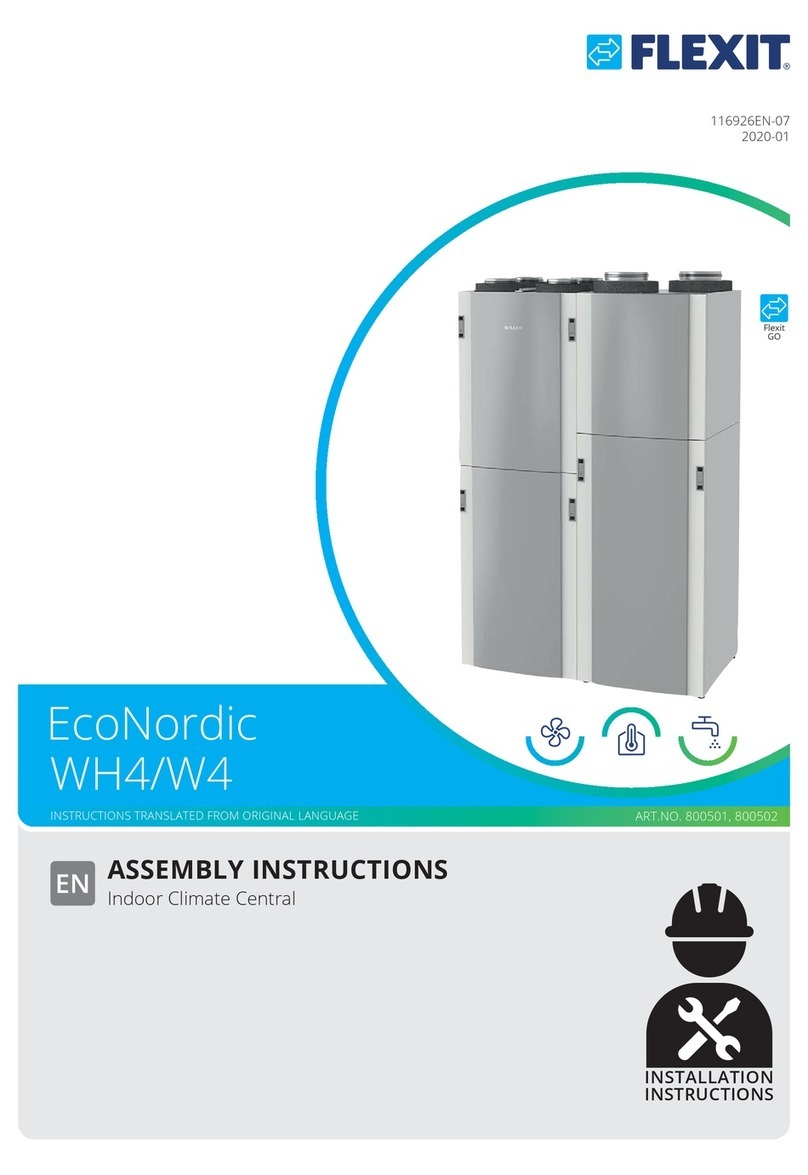
Flexit EcoNordic WH4 User manual

ASSEMBLY INSTRUCTIONS
Indoor Climate Central
ART.NO. 800501, 800502
116926EN-11
2023-08
INSTALLATION
INSTRUCTIONS
EcoNordic
WH4/W4
INSTRUCTIONS TRANSLATED FROM ORIGINAL LANGUAGE
Flexit
GO

2
ECONORDIC WH4/W4
Contents
1. General ..........................................................................................................................5
1.1. Disclaimer...........................................................................................................5
1.2. Warranty.............................................................................................................5
1.3. Manufacturer .....................................................................................................5
1.4. Service and support ..........................................................................................5
1.5. Disposal ..............................................................................................................5
1.6. Validation............................................................................................................5
2. Safety .............................................................................................................................6
2.1. Symbols and stickers.........................................................................................6
2.2. Warnings in the manual....................................................................................6
2.3. General safety rules ..........................................................................................7
3. Transport.......................................................................................................................8
3.1. Components included.......................................................................................8
3.1.1. Supplied in tank module........................................................................9
3.1.2. Supplied in chassis module ...................................................................9
3.1.3. Supplied in ventilation module .............................................................9
3.1.4. Supplied in heat pump module ............................................................9
4. System overview........................................................................................................ 10
4.1. System diagram W4 ....................................................................................... 10
4.2. System diagram WH4..................................................................................... 11
4.3. Component overview for electricity ............................................................. 12
4.4. Component overview for water.................................................................... 13
4.5. Component overview for ventilation ........................................................... 14
5. Assembly ....................................................................................................................15
5.1. Space requirements for heat pump............................................................. 16
5.2. Assembly of modules..................................................................................... 17
5.2.1. Prerequisites......................................................................................... 17
5.2.2. Instructions........................................................................................... 17
5.3. Installation of frost protection damper ....................................................... 25
5.4. Assembly of ventilation ducts ....................................................................... 26
5.4.1. Prerequisites......................................................................................... 26
5.4.2. Instructions........................................................................................... 26
5.5. Electrical installation ...................................................................................... 27
5.5.1. Before you start ................................................................................... 27
5.5.2. Internet access ..................................................................................... 27
5.5.3. If accessories are used ........................................................................ 27
5.5.4. Circuit diagram and conversion, electricity ...................................... 27
5.5.5. Prerequisites......................................................................................... 28
5.5.6. Control and accessories...................................................................... 28
5.5.7. Connection of a frost protection damper......................................... 30
5.5.8. Voltage supply ...................................................................................... 30
5.6. Water and pipe work...................................................................................... 31
5.6.1. Domestic Hot Water Recirculation System ...................................... 31
5.6.2. Incoming water .................................................................................... 31
5.6.3. Water quality ....................................................................................... 31
5.6.4. Water connections............................................................................... 32
5.6.5. Drainage................................................................................................ 32
5.7. Connecting the heating system WH4........................................................... 33
5.7.1. Installation ............................................................................................ 33
5.7.2. Dimensioning ....................................................................................... 33

3
ECONORDIC WH4/W4
6. Commissioning.......................................................................................................... 34
6.1. Prior to commissioning.................................................................................. 34
6.2. Connection ...................................................................................................... 35
6.2.1. No network available........................................................................... 35
6.2.2. Network available ................................................................................ 35
6.3. Connect to the product.................................................................................. 37
6.4. Start-up Guide................................................................................................. 39
7. Adjustment................................................................................................................. 41
6\VWHPGLHUHQFHVEHWZHHQ$QGURLGDQGL26 ........................................... 41
7.2. Initial adjustment, ventilation ....................................................................... 41
7.3. Settings, heating ............................................................................................. 44
8. Technical data............................................................................................................ 45
8.1. Air capacity and sound data.......................................................................... 46
8.2. Pump capacity, heating system .................................................................... 47
8.3. Nipple location................................................................................................ 47
9. Dimensions ................................................................................................................ 48
9.1. Tank module ................................................................................................... 49
9.2. Chassis module............................................................................................... 49
9.3. Ventilation module ......................................................................................... 50
9.4. Heat pump module ........................................................................................ 50

4
ECONORDIC WH4/W4

1.5. Disposal
The product is covered by warranty as stated in the
current conditions of sale, provided that the product
has been used and maintained correctly. Filters are
consumable material.
The symbol on the product indicates that it
must not be treated as household waste.
Instead, it should be taken to a recycling centre
that accepts electrical and electronic
equipment. By disposing of the product
correctly, you contribute to preventing the negative
consequences to health and the environment that may
result from incorrect treatment. For further information
concerning the recycling of the product, contact your
local authority, recycling centre or place of purchase.
Claims arising from faulty or inadequate installation
should be made to the installation company responsible.
The warranty may be invalidated by incorrect use or
gross negligence in the maintenance of the unit.
1.6. Validation
This user manual applies to EcoNordic WH4 and W4.
1. General
Read these instructions carefully before using the unit.
Keep the instructions for future use.
1.1. Disclaimer
NB
In order for the warranty to be
valid, these instructions must be
followed.
i
FLEXIT’s products are subject to ongoing development
and we therefore reserve the right to modify
FRPSRQHQWVVSHFLȴFDWLRQVDQGWKHFRQWHQWVRIWKHVH
instructions without prior notice.
FLEXIT is not responsible or bound by warranty if
these instructions are not followed during installation,
operation or servicing.
FLEXIT guarantees the correct functioning of the unit
RQO\ZLWKRULJLQDORUVSHFLȴHGFRPSRQHQWV
We are not responsible for any typographical errors
that may arise.
1.2. Warranty
The product must be assembled exactly as instructed,
otherwise the warranty will not be valid.
1.3. Manufacturer
Flexit AS, Moseveien 8, N-1870 Ørje, Norway
ZZZȵH[LWFRP
1.4. Service and support
For questions concerning support, contact Flexit.
5
ECONORDIC WH4/W4

2. Safety
2.1. Symbols and stickers
A number of symbols are used for these products.
They are used both for labelling the product itself
and in the installation and user documentation.
Danger - do not touchDanger:
Electrical current
Drainage Outgoing
water
Incoming
water
Stickers in the product
Symbols on the product
Extract air
Outdoor airSupply air
Exhaust air
2.2. Warnings in the manual
The following types of instruction are used in the user
manual.
!
DANGER
$WH[WȴHOGZLWKWKLVFRORXUPHDQV
that life-threatening or serious
injury may result if the instructions
are not observed.
!
WARNING
$WH[WȴHOGZLWKWKLVFRORXUPHDQV
that damage may result if the
instructions are not observed.
!
CAUTION
$WH[WȴHOGZLWKWKLVFRORXUPHDQV
WKDWSRRUHɝFLHQF\RURSHUDWLRQDO
problems with the product may
result if the instructions are not
observed.
NB
$WH[WȴHOGZLWKWKLVFRORXU
means that it contains important
information.
i
6
ECONORDIC WH4/W4

2.3. General safety rules
These safety rules must be followed when you use and
maintain the system. Failure to follow them may result in
injury, death or damage to the equipment.
!
DANGER
It is the responsibility of
the installer to carry out a
comprehensive safety and function
check of the unit.
!
DANGER
All electrical connections must
EHFDUULHGRXWE\DTXDOLȴHG
electrician.
!
DANGER
The product must not be used for
the extraction of combustible or
ȵDPPDEOHJDVHV
!
WARNING
All pipe installation work must be
GRQHE\DTXDOLȴHGSOXPEHU
!
WARNING
The product should be placed
in a room with a drain.
!
WARNING
The incoming water pressure
should not exceed 0.45/4.5 MPa/
bar. If the water pressure exceeds
0.45/4.5 MPa/bar, a pressure
reduction valve (with check valve)
must be installed.
!
CAUTION
Tumble driers must not be
connected to the unit.
7
ECONORDIC WH4/W4

3. Transport
3.1. Components included
10-628611
2018-04
10-628611
2018-04
10-628611
2018-04
10-628611
2018-04
A
B
C
D
E
F
2017 812/2013
ENERG
енергия
•
ενεργεια
52
dB
A
+
Flexit EcoNordic W4
XL
A
+
dB
1405
1 298
1091
kWh/annum GJ/annum
A
B
C
D
E
F
2017 812/2013
ENERG
енергия
•
ενεργεια
52
dB
A
+
Flexit EcoNordic W4
XL
A
+
dB
1405
1 298
1091
kWh/annum GJ/annum
A
B
C
D
E
F
2017 812/2013
ENERG
енергия
•
ενεργεια
52
dB
A
+
Flexit EcoNordic W4
XL
A
+
dB
1405
1 298
1091
kWh/annum GJ/annum
A
B
C
D
E
F
2017 812/2013
ENERG
енергия
•
ενεργεια
52
dB
A
+
Flexit EcoNordic W4
XL
A
+
dB
1405
1 298
1091
kWh/annum GJ/annum
116819-01
2018-04
VEILEDNING • ANVISNING • INSTRUCTION
EcoNordic
3~230V
• 3-pols lask fjernes.
•SROVODVNȵ\WWHVPRWYHQVWUHWLO
RUDQJHRJJU§UHNNHNOHPPHVRP
YLVW
•7RPHGIºOJHQGHODVNHUVHWWHVS§
JU§RJRUDQJHUHNNHNOHPPHVRP
YLVW
•5HPRYHWKHSROHMXPSHUEDU
•0RYHWKHSROHMXPSHUEDUWRWKH
OHIWWRWKHRUDQJHDQGJUD\EORFNV
DVVKRZQ
•7ZRVXSSOLHGMXPSHUEDUVDUH
SODFHGRQWKHJUD\DQGRUDQJH
EORFNVDVVKRZQ
/DVNȵ\WWHVPRWKº\UHWLORUDQJHRJ
JU§UHNNHNOHPPHVRPYLVW
0RYHWKHMXPSHUEDUWRWKHULJKW
WRWKHRUDQJHDQGJUD\EORFNVDV
VKRZQ
.OLVWUHGHQEO§9HWLNHWWHQRYHUGHQUºGH
9HWLNHWWHQ
6WLFNWKHEOXH9ODEHORQWKHUHG9
ODEHO
)OH[LW$6
ZZZȵH[LWQR
230 V
MONTERINGSVEILEDNING
Inneklimasentral
EcoNordic WH4/W4
ART.NR. 800501, 800502
NO
116926NO-02
2018-08
Flexit
GO
VEILEDNING PÅ ORIGINALSPRÅK
BRUKERVEILEDNING
Inneklimasentral
EcoNordic WH4/W4
ART.NR. 800501, 800502
NO
116972NO-02
2018-08
Flexit
GO
VEILEDNING PÅ ORIGINALSPRÅK
a) Navn eller varemerke: Flexit
b) Modellbetegnelse: EcoNordic W4 Art.nr. 800502
c) XL
d) A+
(gjennomsnittlig klimaforhold)
e) oppvarming av vann:
129 %
(gjennomsnittlig klimaforhold)
f) Årlig strømforbruk: 1 298 kWh
(gjennomsnittlig klimaforhold)
g) n.a.
h) Referansetemperatur,
varmtvann: 65°C
i) 52 dB(A)
j) Mulighet for drift kun i perioder
med lav belastning: Nei
k) Forholdsregler:
montering, installasjon og vedlikehold
er beskrevet i bruker- og monterings-
veiledningen.
Les og følg instruksjonene.
l) Intelligent styring: Nei
m) oppvarming av vann:
119 % (kaldere klimaforhold)
153 % (varmere klimaforhold)
n) Årlig strømforbruk: 1 405 kWh (kaldere klimaforhold)
1 091 kWh (varmere klimaforhold)
Flexit EcoNordic
812/2013 Energimerkingsforordningen
814/2013 Økodesignforordningen
116635NO-01
2018-04
Dettedokumentet beskriver:
KOMISJONSFORORDNING(EU) 812/2013 av 18. februar 2013
omutfylling av europaparlaments- og rådsdirektiv 2010/30/EU når det gjelder energimerking av
varmtvannsberedereog lagringstanker samt kombinasjonsløsninger med varmtvannsbereder og
solfangersystem.
KOMISJONSFORORDNING(EU) 814/2013 av 2. august 2013
omgjennomføring av europaparlaments- og rådsdirektiv 2009/125/EF når det gjelder krav til
miljøvennligutforming av varmtvannsberedere og lagringstanker.
A
B
C
D
E
F
2017 812/2013
ENERG
енергия
•
ενεργεια
52
dB
A
+
Flexit EcoNordic W4
XL
A
+
dB
1405
1 298
1091
kWh/annum GJ/annum
!
ADVARSEL!
Hvis vanntilførselen stenges, må EcoNordic
klimasentral settes i servicemodus.
Se www.flexit.no for mer informasjon.
WARNING!
If the water supply is shut off, the
EcoNordic heat pump must be put into
service mode. For more information,
please refer to www.flexit.no
119899-01
10-2021
7DNRSLRJUHWXUQHUGHWWHWLO)OH[LW$60RVHYHLHQUMHSRVW#ȵH[LWQR
*) Må fylles ut
Flexit prosjekt-ID:
Flexit ordrenr.: Fylles ut ved overlevering.
Type aggregat: Serienr.: *)
Type sentralstøvsuger: Serienr.:
1. Kravtil rom - Byggmester/entrepenør
a) Er det behov for ekstra spisslast på varmebærer side av anlegget
b) Er ekstra spisslast installert
c) Econordic er montert og plassert i henhold til veiledning
d) 50cm plass på høyre side av varmepumpe er sikret for adkomst dersom nødvendig
e) Rødt blindlokk er fjernet fra ventilasjonsmodul og varmepumpemodul (ta vare på delene som sitter i lokket)
f) Varmepumpens ører sitter korrekt på skinnene i bunnen og låsen på toppen er aktivert på varmepumpen
J (UURPPHWGHȴQHUWVRPWHNQURPXWHQO\GNUDY
h) Grenser rommet mot oppholdsrom
i) Er nødvendige lydtiltak gjennomført mot oppholdsrom
j) Er nødvendige lydtiltak gjennomført i sjakt for kanalføring
k) Er nødvendige lydtiltak gjennomført på inntak og avkastkanalenes fulle lengde
l) Innkassing over anlegg utført på en servicevennlig måte
SJEKKLISTE
Installasjon EcoNordic
120927-01
2023-05
Dato:
Herved bekreftes at ovenstående punkter er gjennomgått:
Vennligst skriv tydelig med blokkbokstaver og korriger evt. feil opplysninger.
Firmanavn:
*) *)
'DWR 6LJQ 'DWR 6LJQ
Den som overleverer er ansvarlig for at skjemaet fylles ut sammen
PHGEUXNHURJUHWXUQHUHV)/(;Δ7ȂHOOHUVS§YLUNHVJDUDQWLDQVYDU
JA NEI IA Kommentar
1
12
12
11
9
10
18
14
15
16
19
17
4
7
5
10
9
3
2
3 4
13
6
8
8
ECONORDIC WH4/W4

3.1.1. Supplied in tank module
Item Description Number
1 Circuit diagram, electricity 1
2 Assembly instructions 1
3 User manual 1
4 Eco design document 1
5 Eco design label 1
6 Label with cable tie 1
7 Conversion 3N~400 V-3~230V 1
8 Installation checklist 1
9 Label 230V 1
10 Jumper 2
3.1.2. Supplied in chassis module
Item Description Number
9 Door 1
10 Side wall 1
11 8SURȴOH 3
12 8SURȴOHZLWKGRRUODWFK 1
13 Self-tapping screw 17
3.1.3. Supplied in ventilation module
Item Description Number
14 Cable tie 4
3.1.4. Supplied in heat pump module
Item Description Number
15 Drainage plug 1
16 Gasket 1
17 Self-tapping screws 5
18 Venting hose 1
19 Cable tie 2
Installation - checklist
EcoNordic
The person handing over the delivery is
responsible for ensuring that the form
is completed together with the user and
UHWXUQHGWR)/(;Δ7SRVW#ȵH[LWQRȂLIQRW
JXDUDQWHHOLDELOLWLHVPD\EHDHFWHG
9
ECONORDIC WH4/W4

4. System overview
4.1. System diagram W4
FI1
FI2
B4 B6
P2
F10
F20
B32
B30 B31
P1
M22
B1
EB1
M6
M14
M1
M2
M3
M8
B10
B16
B11
EB10
EB11
M31
B14 B15
M20
F15
M23
B3
HR-R
Pos. Beskrivelse
B1 Temperature sensor, supply air
B3 Temperature sensor, extract air
B4 Temperature sensor, outdoor air
B6 Temperature sensor, exhaust air
B10 Temperature sensor, upper part of
tank
B11 Temperature sensor, middle of tank
B12 :+7HPSHUDWXUHVHQVRUKHDWLQJ
system feed
B13 :+7HPSHUDWXUHVHQVRUKHDWLQJ
system return
B14 Temperature sensor, electric heating
EDWWHU\)7+
B15 Temperature sensor, from tank to
heat pump
B16 Temperature sensor, lower part of
tank
B30 Temperature sensor, HP water outlet
B31 Temperature sensor, HP water inlet
B32 Temperature sensor, HP air inlet
M1 Supply air fan
M2 Extract air fan
M3 Rotor motor
M6 Exhaust air damper
M8 Heat pump damper
M11 :+5HJXODWLQJYDOYH'+:KHDWLQJ
system
M12 :+6KXWWOHYDOYHWDQNKHDWSXPS
M13 :+&LUFXODWLRQSXPSKHDWLQJ
system
M14 Frost protection damper
M20 Compressor
M22 Fan HP
M23 Expansion valve HP
M31 Circulation pump primary circuit
F10 Overheating thermostat EB1
F15 Overheating thermostat electric
HOHPHQW)7+PDQXDOUHVHW
F20 Overheating thermostat EB1
EB Heating battery, electric
(%
EB11
Water heater, electric
FI1 2XWGRRUDLUȴOWHU
FI2 ([WUDFWDLUȴOWHU
P1 Pressure sensor, supply air
P2 Pressure sensor, extract air
HR-R Rotary wheel-type heat exchanger
10
ECONORDIC WH4/W4

4.2. System diagram WH4
FI1
FI2
B4 B6
P2
F10
F20
B32
B30 B31
P1
M22
B1
EB1
M6
M14
M1
M2
M3
M8
B10
B16
B11
EB10
EB11
B14
B15
B13
B12
M31
M12M11
M13
M20
F15
M23
B3
HR-R
11
ECONORDIC WH4/W4

12
ECONORDIC WH4/W4
4.3. Component overview for electricity
3
6
5
4
7
1
12
9
10
2
11
13
8
The unit can be converted for 230 V, 3-phase
Item Designation
1 Connection for external control etc.
2 Battery
3 Damper motors
4 Air intake fan
5 Rotor
6 Air outlet fan
7 Control centre for ventilation and water
8 Connection box for module connection
Item Designation
9 Control unit for heat pump
10 Electrical connections for heat pump
11 9ROWDJHFRQQHFWLRQFRQWUROXQLW
12 Circulation pump primary circuit
13 Flow through heater
14 5HJXODWLQJYDOYH'+:KHDWLQJV\VWHP
15 6KXWWOHYDOYHWDQNKHDWSXPS
16 Circulation pump heating system
Tank module WH4Tank module W4
12
11
13
14
15
16

13
ECONORDIC WH4/W4
4.4. Component overview for water
3
6
5
2
1
4
7
12
89
10
11
Item Designation
1 Air extraction
2 Water connection for heat pump
3 Connection for drainage hose
4 Pipe system
5 Hot water tank
6 Circulation pump
7 Electric water heater
8 External water connections
Tank module WH4Tank module W4
Item Designation
96KXWRYDOYH
10 'UDZRYDOYH
11 Safety valve
12 Drainage cup for draining and safety valve
13 Circulation pump heating system
14 Plate heat exchanger
15 5HJXODWLQJYDOYH'+:KHDWLQJV\VWHP
16 6KXWWOHYDOYHWDQNKHDWSXPS
6
9
2
1
4
7
12
8
3
13
14
15
16
10
11
5

4.5. Component overview for ventilation
1
2
4
5
8
3
7
6
5
Item Designation
1 Air connections
2([WUDFWDLUȴOWHU
3 Post-heating battery
46XSSO\DLUȴOWHU
5 Damper
6 Air intake fan
7 Rotor
8 Air outlet fan
14
ECONORDIC WH4/W4

500 mm
20 mm
20 mm
3
2
1
mm
0m
0m
500
0m
0m
0m
5. Assembly
INFO! First read the instructions
”Preparations” before starting
assembly.
i
7KHSURGXFWLVDVVHPEOHGRQWKHȵRRU
Assemble in the following order:
On the right-hand side, a clearance of
500 mm is recommended.
If service is required, service personnel
are dependent on space to carry out
the work.
Any additional costs arising from this
will not be covered by Flexit.
Preparations
15
ECONORDIC WH4/W4

500 mm
4
5.1. Space requirements for heat pump
INFO When installing EcoNordic
it is important to follow the Flexit
installation instructions.
i
If it becomes necessary to replace the fan, service
personnel will require space to carry out the work.
Any additional costs arising from this will not be covered
by Flexit.
16
ECONORDIC WH4/W4

5.2. Assembly of modules
!
WARNING
Risk of cuts.
Wear protective gloves during
assembly.
NB
Before beginning assembly, make
sure that the doors on module 1
and module 3 have been removed.
i
5.2.1. Prerequisites
Number of persons
2
Time
45 min.
Tools
Screwdriver and TX20 bits
Wrench, 24 mm
Wrench, 8 mm
Spirit level
1. 2.
1
3
1.
2.
2.
1
1
2
3
5.2.2. Instructions
17
ECONORDIC WH4/W4

54
76
98
18
ECONORDIC WH4/W4

ERWWRP
3
10
12
11
13
1514
19
ECONORDIC WH4/W4

1.
2. Max 30°
16 17
18
20
19
21
OBS!
20
ECONORDIC WH4/W4
Other manuals for EcoNordic WH4
2
This manual suits for next models
3
Table of contents
Other Flexit Temperature Controllers manuals
Popular Temperature Controllers manuals by other brands
Linear Technology
Linear Technology DC2131A Demo Manual
thermastor
thermastor Ultra-Aire DEH 3000R Installer's & owner's manual
Suncourt
Suncourt DUCTSTAT DS100 Operation instructions
Lake Shore
Lake Shore 332 user manual

Lily Tech
Lily Tech ZL-7817A instruction manual
Bitron Video
Bitron Video AV2010/27A quick start guide
