manuals.online logo
Brands
  1. Home
  2. •
  3. Brands
  4. •
  5. Lily Tech
  6. •
  7. Temperature Controllers
  8. •
  9. Lily Tech ZL-7817A User manual

Lily Tech ZL-7817A User manual

Suzhou Lily Tech. Co., Ltd.
Page 1, Total 4 Pages
ZL-7817A Temperature Controller
Instruction Manual V1.2b
Introduction
This new version provides optional PID and on/off control.
Internal control resolution now is 0.01C degree to reach better control
result.
Integrated SSR output with 5A rate power driving ability.
An auxiliary output: timer on/off, and/or high temperature protection
Specification
Sensor: NTC, R25℃= 10K, B25/50℃= 3470K
Setting range: -40.0 ~ 130.0℃
Power supply: 100 ~ 240Vac, 50/60Hz
Output R1: 5A, 250Vac (rated current)
Output R2: 7A, 250Vac (resistive)
Working: -10 ~ 45℃, 5 ~ 85%RH without dew
Case materials: PC + ABS fire proof
Protection level: IP65 (Front side only)
Dimension: W78 x H34.5 x D71 (mm)
Installation drilling: W71 x H29 (mm)
Display
Display
Display
Function
On
Blinking
Heater status
Heater output R1 is energized
Timer output status
Timer output R2 is energized
PID auto tune status
PID auto tuning
Failure
Warning
Set status
Setting
E1
Failure
Sensor failure
Hi
Failure
High temperature warning
Lo
Failure
Low temperature warning
iA
Failure
External warning input effective
UnL
Restore to factory settings
Will restore to factory settings
At1
Auto tuning fails
Temperature not stable during Auto tuning
At2
Auto tuning fails
Temperature vibration level not satisfied
At3
Auto tuning fails
Temperature vibration period not satisfied
SUc
Auto tuning finished
Auto tuning finished successfully
Model, version display
After reset, the model (ZL-7817 A) and version (version 1.0) will display
consecutively:
Operation
Set set-point (SP). Factory default set is 35.0℃
Keep〖S〗depressed for 3 seconds to enter into temperature setting status:
blinks, the SP value displays.
Press〖▲〗or〖▼〗to set the value.
Press〖S〗to save and exit the status.
The status will exit, and the value will be saved, when there is no key operation for 30 seconds.
Suzhou Lily Tech. Co., Ltd.
Page 2, Total 4 Pages
Set system parameters
Keep〖P〗depressed for 3 seconds to enter into parameter setting status:
blinks, dispay shows “U10”, the 1st system parameter code.
Press〖▲〗or〖▼〗to select parameter code.
Press〖S〗to show the value of the parameter.
Press〖▲〗or〖▼〗to the value of the parameter.
Press〖S〗to return back to parameter code selection.
In this way, we can check and/or set all parameters.
Keep〖P〗depressed for 3 seconds to save and exit the status.
The status will exit, and the value will be saved, when there is no key operation for 30 seconds.
If parameter U99 value is not “0000”, the password (the value of U99) is required to enter into parameter setting status:
After〖P〗depressed for 3 seconds, display shows “---0”.
Press〖▼〗to select the digit of password, press〖▲〗to set the value of the digit.
After 4 digits are set, press〖S〗to enter the password.
If the password is correct, enter into the parameter setting status. Else exit.
System parameter table:
Code
Function
Range
Remark
Factory
Setting
U10
Set-point (SP)’s low limit
-40.0 ~ 130.0℃
-40.0℃
U11
Set-point (SP)’s high limit
-40.0 ~ 130.0℃
130.0℃
U12
Low temperature warning point (relative)
0.0 ~ 130.0℃
Absolute low temperature warning point: SP - U12
35.0℃
U13
High temperature warning point (relative)
0.0 ~ 130.0℃
Absolute high temperature warning point: SP + U13
130.0℃
U14
Hysteresis
0.0 ~ 20.0℃
Only effective when U74 = 1
0.2℃
U30
Sensor calibration value
-20.0 ~ +20.0℃
0.0℃
U40
Output R2 timer on period’s time unit
0 ~ 2
0: Second; 1: Minute; 2: Hour
1
U41
Output R2 timer on period’s time
1 ~ 9999
120
U42
Output R2 timer off period’s time unit
0 ~ 2
0: Second; 1: Minute; 2: Hour
1
U43
Output R2 timer off period’s time
1 ~ 9999
120
U46
Output R2 working mode
0 ~ 2
0: Timer on/off;
1: Over temperature protection;
2: Timer on/off + Over temperature protection
0
U60
External input warning working mode
0 ~ 2
0: Disable; 1: Normal open; 2: Normal close
0
U70
PID proportional coefficient Kp
0.1 ~ 999.9
2.6
U71
PID integration coefficient Ti
0 ~ 999.9
500
U72
PID differential coefficient Td
0 ~ 999.9
50
U73
PID output amplitude
10 ~ 100%
Percent of full heater power rate.
50%
U74
Control method
0 ~ 1
0: PID control; 1: hysteresis control
0
U99
Password
0000 ~ 9999
If 0000, password disabled
0000
Control
Timer output R2
During timer on period (U41, U40), the R2 will be energized.
During timer off period (U43, U42), the R2 will be de-energized.
Temperature control
PID control (U74 = 0)
PID control. The output for heater is R1.
Hysteresis control (U74 = 1)
When measured ≥ Set-point (SP), R1 de-energized. When ≤ Set-point (SP) –U14, R1 100% energized.
Suzhou Lily Tech. Co., Ltd.
Page 3, Total 4 Pages
Over temperature protection
When the protection function is enabled (U46 = 1 or 2), and if measured temperature ≥ high temperature warning point (SP + U13),
R2 will be energized.
Over temperature warning
If measured temperature ≥ high temperature warning point (SP + U13), display blinks, buzzer beeps.
If measured temperature ≤ low temperature warning point (SP - U12), display blinks, buzzer beeps.
External input warning working mode
U60 = 0: Disable. The external input warning function is disabled;
U60 = 1: Normal open. When closed, warning, the R1 will be de-energized, the R2 still works;
U60 = 2: Normal close. When open, warning, the R1 will be de-energized, the R2 still works;
Buzzer warning
When there is failure or warning, the buzzer beeps.
Press〖P〗can stop beeping.
When the failure or warning disappears, the buzzer stops beeping.
Sensor
The sensing resolution is 0.1 Celsius degree. The sensor has tolerance. After calibration (U30), the absolute sensing accuracy
could be 0.1 degree.
When the sensor fails (open or short), the display blinks, and there will be warning, the R1 will be de-energized, the R2 still works.
Restore system parameters to factory settings.
Keep〖P〗and〖▲〗depressed simultaneously for 5 seconds, display shows “UnL”. Press〖▼〗twice, all system parameter settings
will be restored to factory setting.
PID parameters Auto Tuning (AT)
With auto tuning, we can find optimized PID parameters for most control system.
Auto tuning step:
1. Set driving power rate (percent of full heater power rate, U73), or
set it in step 4.
2. Set Set-point (SP).
3. In control status (not setting status), keep〖▲〗and〖▼〗depressed
for 5 seconds to enter into auto tuning mode. U73’s value displays,
blinks.
4. Press〖▲〗and〖▼〗to set the amplitude value (U73).
5. Press〖P〗to start auto tuning.
The measured temperature will rise, vibrate around SP for several
times.
When disappears,
if “At1/At2/At3” displays, auto tuning fails;
if “SUc” displays, auto tuning finished, and the PID parameters got.
Press any key, the “At1/2/3, SUc” disappeared, and start temperature control.
If never disappears, if it is because of lower power rate, set bigger value of U73, tune again.
Note:
a.PID control, or hysteresis control?
Try hysteresis control 1st (U74 = 1):
1. Now is full power rate heating. If room temperature is not able to reach SP at reasonable time, increase the heater power
rate.
2. If the temperature overshoot to SP ≤0.2℃, or over falling to (SP –U14) ≤0.2℃: auto tuning is not able to get the PID
parameters correctly. In fact, this kind of system may be unnecessary for PID control.
3. If all are ok, try PID auto tuning.
Suzhou Lily Tech. Co., Ltd.
Page 4, Total 4 Pages
Try auto tuning (U74 = 0). If the PID control result is good, then use PID control.
The following will also make auto tune failure, or get wrong parameters:
⚫The room temperature vibration amplitudes differ too much.
⚫The room temperature vibration periods differ too much.
⚫The room temperature changes not smoothly, because of some interference.
b.Try to get best parameters
When:
the environment temperature changed a lot, the heat dissipating speed changed,
object inside changed a lot, the heat volume changed,
the heater changed, the heat inertia changed,
air flow speed inside changed a lot, sensing speed changed
and so on,
it needs auto tuning again.
c. PTC heater
PTC has a Curie point parameter. When PTC’s temperature is high than Curie point, its power rate will be reduced to almost zero,
the PID control will fail.
With higher Curie PTC heater, with good dissipator for heater, with high air flow speed around heater to avoid the failure.
d.Manual tuning principle
Manual tuning could change the control result.
Increase Kp (U70), increase the speed of control, but more overshoot and bigger vibration.
Increase Ti (U71), get more accurate temperature, but need longer time to reach SP after stating heating.
Increase Td (U72), fast reaction to temperature changes, but add more “small noise” to the control result.
Installation
Attention
⚫Wiring work should be manipulated by certified technicians.
⚫Wrong connection could damage the controller, and the loads.
⚫Sensor and input signal wires should not be laid together with power supply wire, and even in same pipe.
⚫Sensor wire is better as short as possible. Not wind the redundant length wire to electrical noise equipment.
⚫The loads should be within the specification of the controller output driving ability. If using ac/dc module as load, or tungsten lamp,
or motor, following the below requirements to avoid surging current damaging or shorten the life time of the controller outputs:
For ac/dc module as load, the rated current should be no more 1/10th of output specification under pure resistance.
For tungsten lamp as load, the rated current should be no more 1/15th of output specification under pure resistance.
For motor, the rate current should be no more 1/5th of output specification under pure resistance.
For example: if drive a 1100W tungsten lamp with 5A (pure resistance spec.) relay, the relay contactor will be burnt immediately.
⚫Don’t touch inside components;
⚫Avoid installing controller in the following environment:
More wet than 90%RH, or easily dew; Vibrating, or will be shocked; Possible sprayed; Under erosive air; Under explosive air.
Step
1st: Insert into drilling hole 2nd: Clamp
Electrical Wiring

Other Lily Tech Temperature Controllers manuals

Lily Tech ZL-1000 User manual

Lily Tech

Lily Tech ZL-1000 User manual

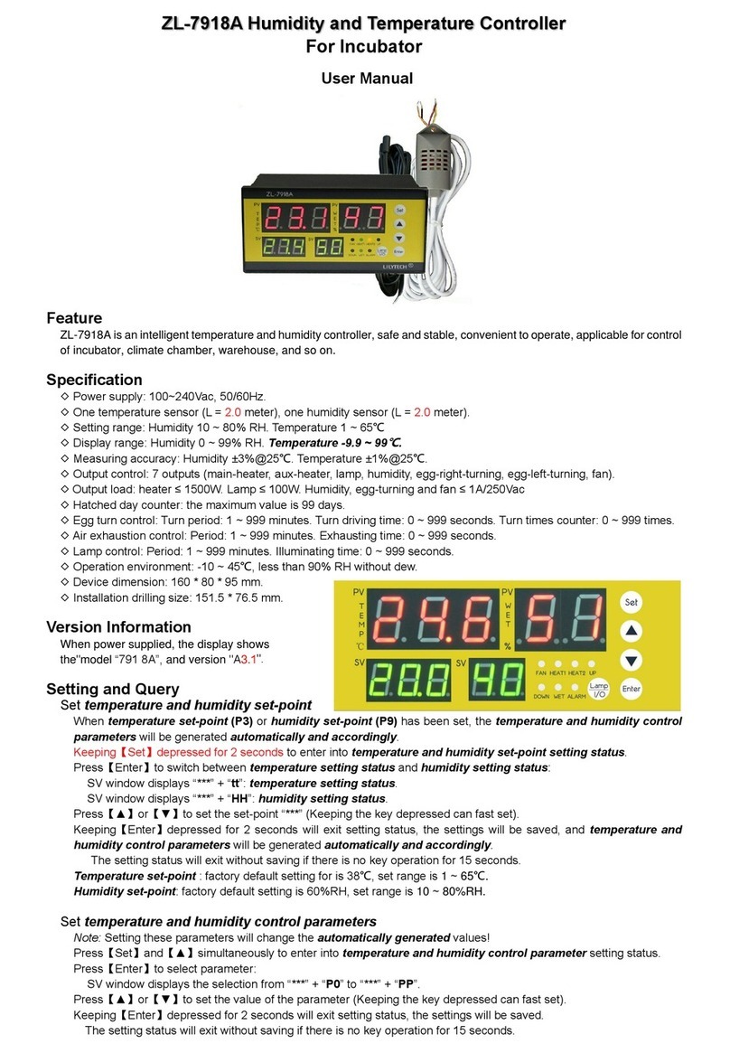
Lily Tech ZL-7918A User manual

Lily Tech

Lily Tech ZL-7918A User manual

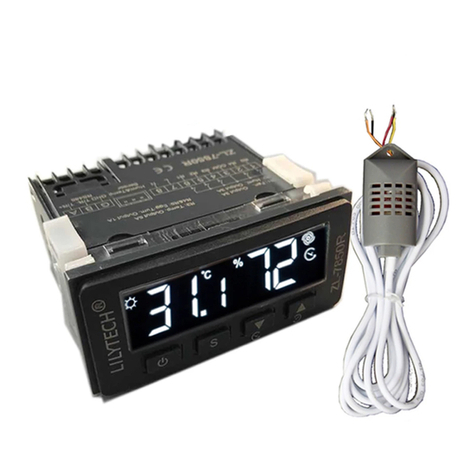
Lily Tech ZL-7850R User manual

Lily Tech

Lily Tech ZL-7850R User manual

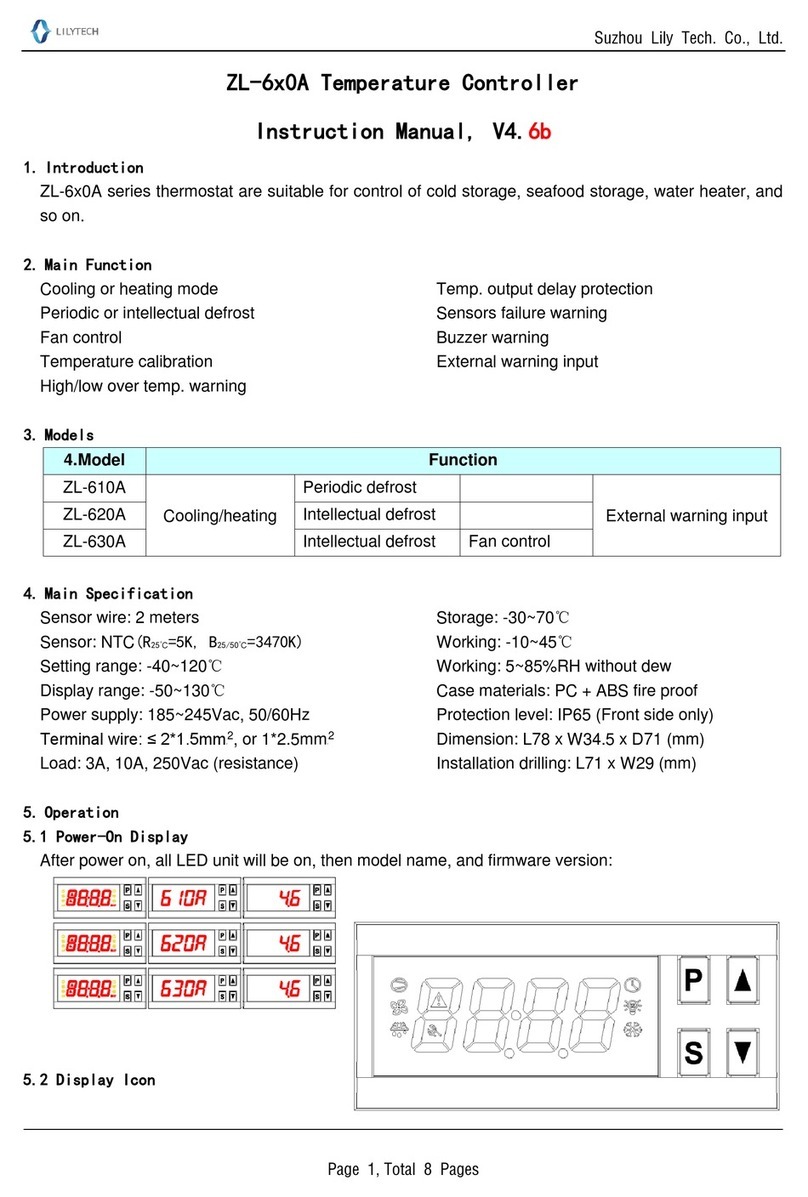
Lily Tech ZL-6 0A Series User manual

Lily Tech

Lily Tech ZL-6 0A Series User manual

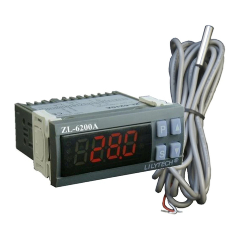
Lily Tech ZL-6200A User manual

Lily Tech

Lily Tech ZL-6200A User manual

Lily Tech ZL-7850A User manual

Lily Tech

Lily Tech ZL-7850A User manual

Popular Temperature Controllers manuals by other brands

Teracom TSM400-4-TH user manual

Teracom

Teracom TSM400-4-TH user manual

LK Armatur SmartComfort LK 110 quick start guide

LK Armatur

LK Armatur SmartComfort LK 110 quick start guide

Ecodhome 01335-1850-00 installation manual

Ecodhome

Ecodhome 01335-1850-00 installation manual

dixell XR720C operating instructions

dixell

dixell XR720C operating instructions

S+S Regeltechnik HYGRASREG AH-30W Operating Instructions, Mounting & Installation

S+S Regeltechnik

S+S Regeltechnik HYGRASREG AH-30W Operating Instructions, Mounting & Installation

CLIMASET SDT Series user guide

CLIMASET

CLIMASET SDT Series user guide

Myson MEP1c User instructions

Myson

Myson MEP1c User instructions

Franke ZAQUA020 Installation and operating instructions

Franke

Franke ZAQUA020 Installation and operating instructions

Wavelength Electronics LDTC2/2E DATASHEET AND OPERATING GUIDE

Wavelength Electronics

Wavelength Electronics LDTC2/2E DATASHEET AND OPERATING GUIDE

EOS ECON 45H2 Assembly and operating instruction

EOS

EOS ECON 45H2 Assembly and operating instruction

Watlow 316-42-4-1 Installation & maintenance manual

Watlow

Watlow 316-42-4-1 Installation & maintenance manual

Omron E5CSV - datasheet

Omron

Omron E5CSV - datasheet

El-Björn TF 9EL manual

El-Björn

El-Björn TF 9EL manual

Danfoss ECL Comfort 210 installation guide

Danfoss

Danfoss ECL Comfort 210 installation guide

Aurora ZS Standard user guide

Aurora

Aurora ZS Standard user guide

Omega CN4000 Series user guide

Omega

Omega CN4000 Series user guide

Airmar Technology Corporation T42 Owner's guide & installation instructions

Airmar Technology Corporation

Airmar Technology Corporation T42 Owner's guide & installation instructions

Fuji Electric PXR3 Series Operation manual

Fuji Electric

Fuji Electric PXR3 Series Operation manual

manuals.online logo
manuals.online logoBrands
  • About & Mission
  • Contact us
  • Privacy Policy
  • Terms and Conditions

Copyright 2025 Manuals.Online. All Rights Reserved.