FlexLink X65 User manual

5763EN-4
X65 ASSEMBLY MANUAL


Created by EBCCW 00:06
i
X65 System
© Flexlink AB 2014
All Rights Reserved
No part of this program and manual may be used, reproduced, stored or
transmitted in any form or by any means without the written permission of
FlexLink AB. The contents of this manual are for informational use only. All
information and specifications contained in this document have been care-
fully checked to the best efforts of FlexLink AB, and are believed to be true
and accurate as of time of publishing. However, due to continued efforts in
product development FlexLink AB reserves the right to modify products
and its manuals without notice.
FlexLink AB assumes no responsibility or liability on any errors or inaccura-
cies in this program or documentation. Any kind of material damages or
other indirect consequences resulting from any FlexLink AB´s product part,
documentation discrepancies and errors or non-anticipated program be-
havior are limited to the value of appropriate products purchased from Flex-
Link AB. The products are delivered to the customer at the ’as is’ state and
revision level they are on the moment of purchasing, and are declared in
detail in the license agreements between FlexLink AB and user. User ac-
cepts and is obliged to follow the guidelines stated in the separate license
agreement needed in using any parts of this product package.

ii X65 System

Created by EBCCW 00:06
iii
X65 System
Table of contents
1Safety 1
1. 1 Sy s t e m i n f o r m a t i o n 1
1.2 Important safety conditions 1
2 Introduction 3
2.1 Assembly information 3
2.2 Scope 3
2.3 Audience 3
2.4 Prerequisites 3
2.5 Hints and tips 3
2.6 Reference symbols 4
3 Support assembly 5
3.1 Support systems assembly 7
3.2 Support feet assembly 9
3.3 End plate assembly 11
3.4 Adjustable foot assembly 13
3.5 Three-point support feet assembly 15
3.6 Height adjustment assembly 17
3.7 Support bracket assembly 21
3.8 Support bracket assembly 27
3.9 Support bracket assembly 35
3.10 Foot plate assembly 37
3.11 Guide rollers assembly 41
3.12 Support bracket for HNLP/HNRP drive units 45
3.13 Support adapters for horizontal bend
drive units 49
4 Conveyor assembly 53
4.1 Idler end unit 55
4.2 Horizontal bend drive unit, with slip clutch 57
4.3 Horizontal bend drive unit, no slip clutch 63
4.4 End drive unit, direct drive with slip clutch 69
4.5 End drive unit, direct drive, no slip clutch 77
4.6 End drive unit, suspended with slip clutch 83
4.7 End drive unit, guided chain with slip clutch 85
4.8 End drive unit, guided chain, no slip clutch 91
4.9 Intermediate drive unit, no slip clutch 95
4.10 Intermediate drive unit, no slip clutch 101
4.11 Synchronous drive unit 105
4.12 Beam section for chain installation 111
4.13 Idler bend unit 113
4.14 Vertical bend 115
4.15 Plain bend 117
4.16 Wheel bend 119
4.17 X-bend 121

iv X65 System
5 Assembly slide rail 127
5.1 Slide rail mounting 129
5.2 Mounting slide rail on idler end unit 131
5.3 Joining slide rail ends 133
5.4 Fixing slide rail to the conveyor using
aluminium rivets 135
6 Mounting conveyor chain 137
6.1 Mounting conveyor chain using a
beam section 139
6.2 Mounting chain on drive units 145
6.3 Mounting chain on Intermediate drive units 149
7 Assembly Guide Rail 153
7.1 Mounting guide rails 155
7.2 Mounting guide rails 157
7.3 Connecting plug 159

Safety
Created by EBCCW 00:06
1
X65 System
1 Safety
The machine has been designed in such a way, that it can be used and
maintained in a safe way. This holds for the application, the circumstances
and the instructions described in the manual. Any person working with or
on this machine should study the manual and follow the instructions. It is
the responsibility of the employer to make sure that the employee is famil-
iar with and follows these instructions.
The company or the country in which the machine is used may require ex-
tra safety measures. This particularly applies to the working conditions.
This manual does not describe how these are to be complied with. In case
of doubt, consult your government or safety officer!
1.1 System information
The project number and/or general drawing number shall always be speci-
fied when communicating with FlexLink with respect to the machine.
1.2 Important safety conditions
At the moment that the machine is going to be operated by a user, the fol-
lowing safety conditions must be met:
• Make sure that children or animals have no access to the machine
and its surrounding area by, for example, screening off the ma-
chine with a fence.
• Only persons who have read and understood the operating in-
structions are allowed to operate, maintain and clean the ma-
chine.
• Do not reach into the machine while it is running or on. Even if the
machine is not running, it can be ‘on’, which means start operating
automatically.
• Safety provisions, such as side plating, bottom plating, emergen-
cy stops and detectors may not be removed or deactivated while
the machine is running.
• Provide good ambient lighting to enable the operator to work well
and orderly with the machine.

Safety
2X65 System
General
• Incorrect use of the equipment can cause personal injury.
• Do not stand or climb on the equipment.
• Do not wear clothing or other articles that can fasten in the ma-
chine.
• Follow the instructions in this user manual when transporting the
machine. FlexLink AB must approve all modifications or changes
to this machine.
• Only use recommended spare parts.
• Only authorised personnel may open electrical units.
• FlexLink is not responsible for damage if service on the equip-
ment is not performed in accordance with this assembly manual.
Maintenance and Service technicians
Service technicians must have:
• Sufficient knowledge for reading technical information
• Ability to comprehend technical drawings
• Basic knowledge of mechanics
• Sufficient knowledge in the use of hand tools
• Skilled (EN ISO 12100:2010)
Electricians
Electricians must have:
• Experience from similar installations
• Sufficient knowledge to work from drawings and wiring diagrams
• Knowledge of local safety regulations for electrical power and au-
tomation
• Skilled (EN ISO 12100:2010)
• To avoid risks, only experienced personnel with technical knowl-
edge and experience may perform repair work on the machine's
electronics components.
Operators
To correctly use the equipment, operators must have appropriate training
and/or experience.

Introduction
4X65 System
2.6 Reference symbols
In most cases of assembling the drive units in chapter 4, Conveyor assem-
bly, the slide rail and chain needs to be installed before the assembly can
be completed. Therefor the underlying symbols will be used to refer the
reader to the chapters concerning mounting of slide rail and chain, instead
of showing the steps repeatedly.
n°1 refer to chapter 5, Assembly slide rail, while n°2 refer to chapter 6,
Mounting conveyor chain.
12
Support assembly
Created by EBCCW 00:06
5
X65 System
3 Support assembly

Support assembly
6X65 System
Created by EBCCW 00:06
7
X65 System
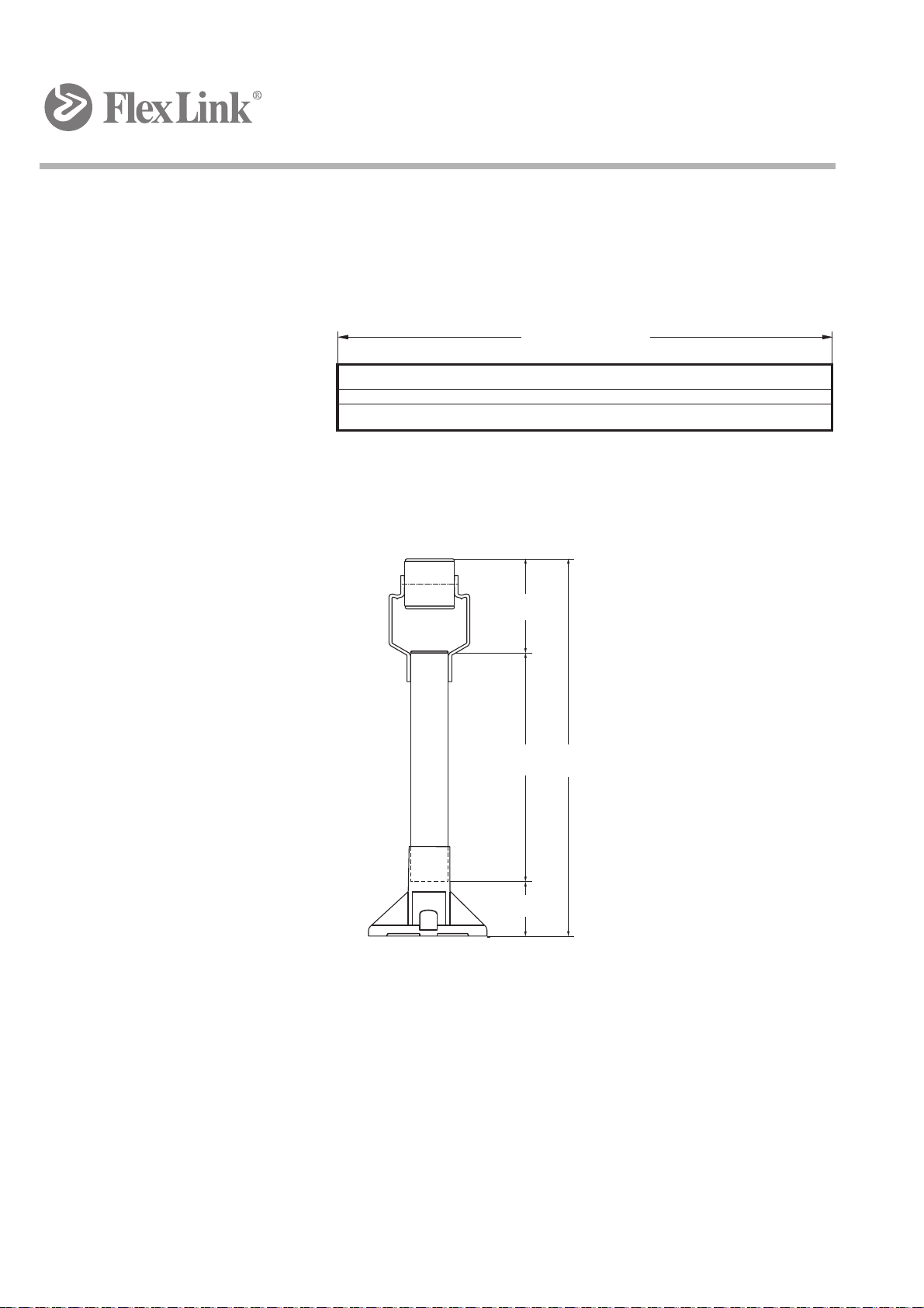
3.1 Support systems assembly
Most conveyor support designs are based on vertical support beams com-
bined, if necessary, with horizontal support beams. The conveyor must be
supported at regular intervals not exceeding 3 000 mm, and always place
a support as close to the drive unit as possible.
3.1.1 Beam cutting length
L = H – h1 – h2
The beam length required to obtain a specific conveyor height H depends
on the conveyor size, foot type and beam support bracket. In this case, CS
beam support brackets are used.
In the formula H represents the height from the floor to the top of a stand-
ard plain chain. Most support combinations permit height adjustments,
both at the foot, and at the beam support brackets.
L<3 000 mm
h2
h1
H
L

8X65 System
Created by EBCCW 00:06
9
X65 System
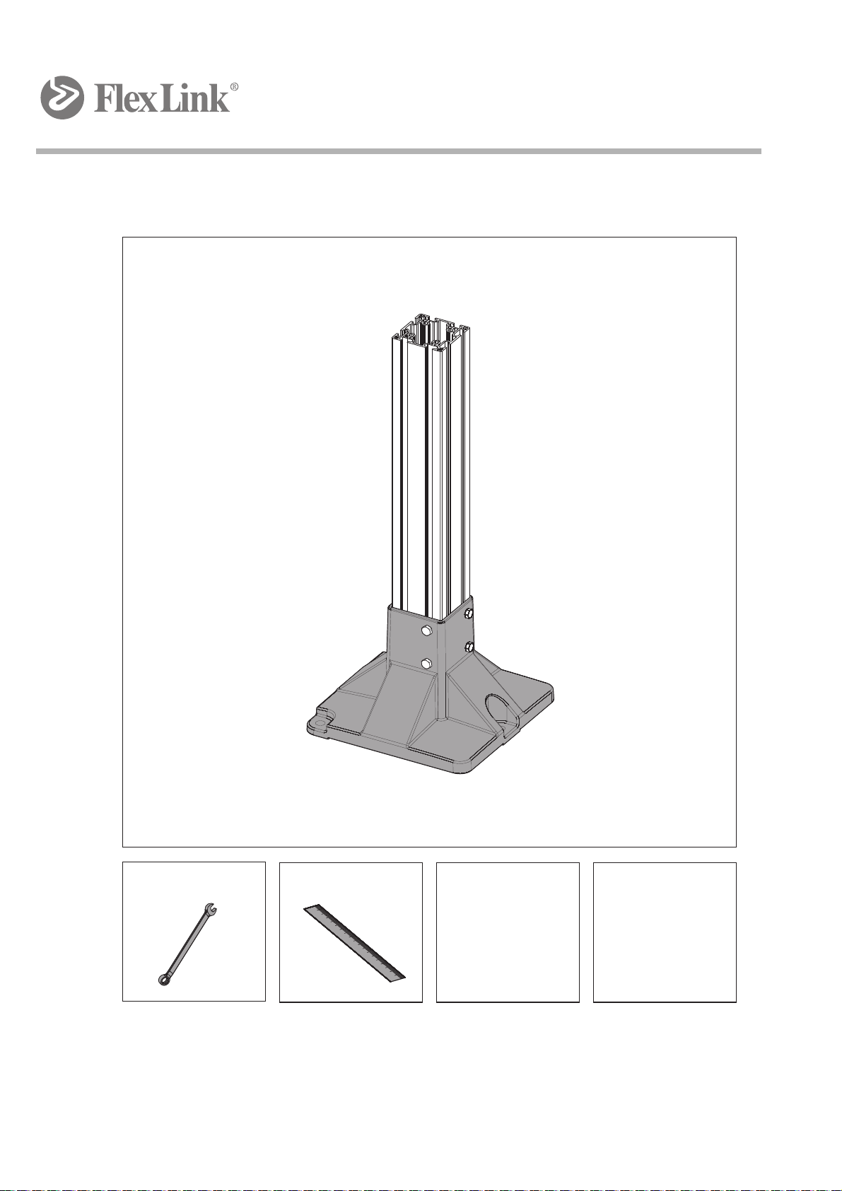
3.2 Support feet assembly
13 mm Ruler
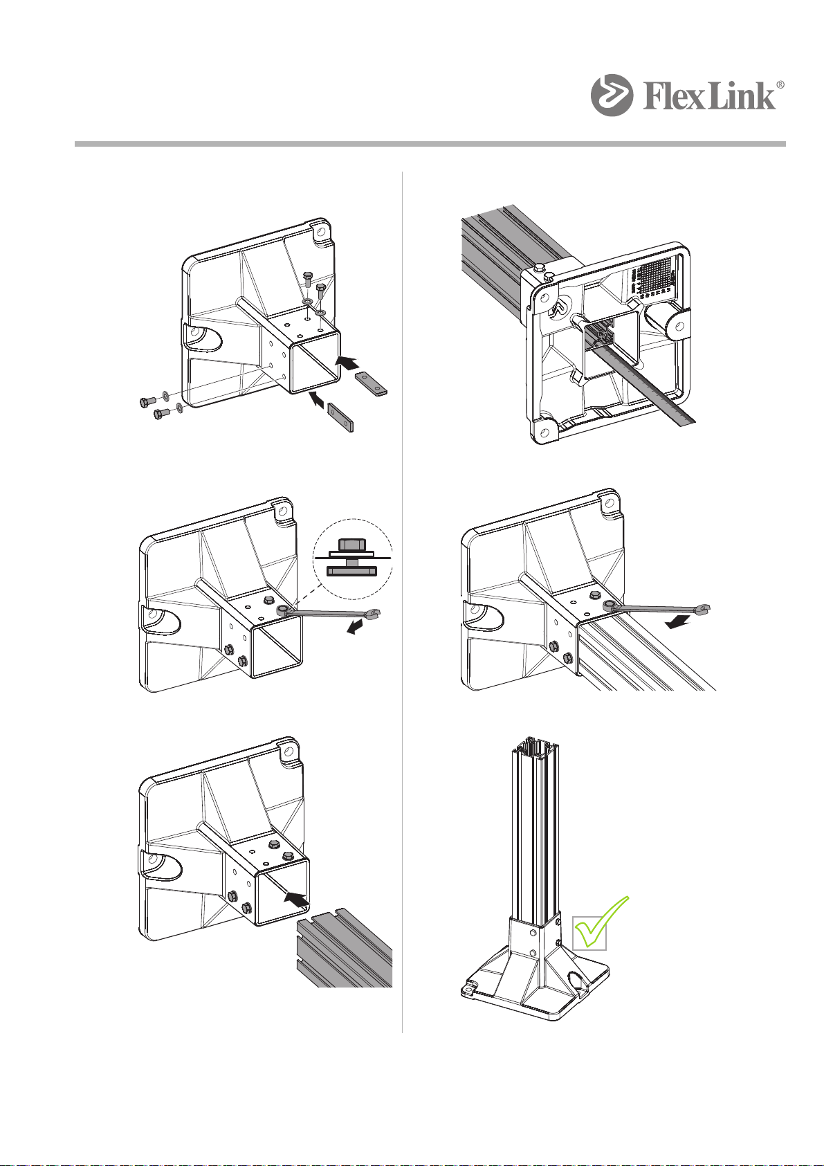
10 X65 System
1 4
2 5
3 6
50 mm
x4
x4
Created by EBCCW 00:06
11
X65 System
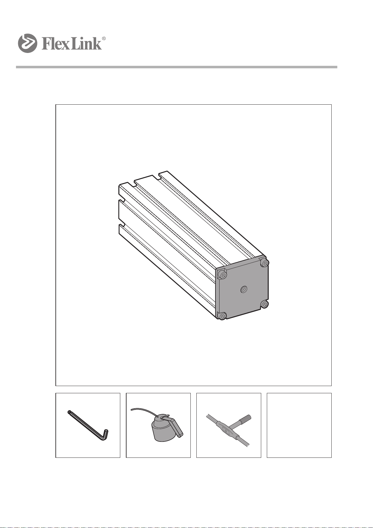
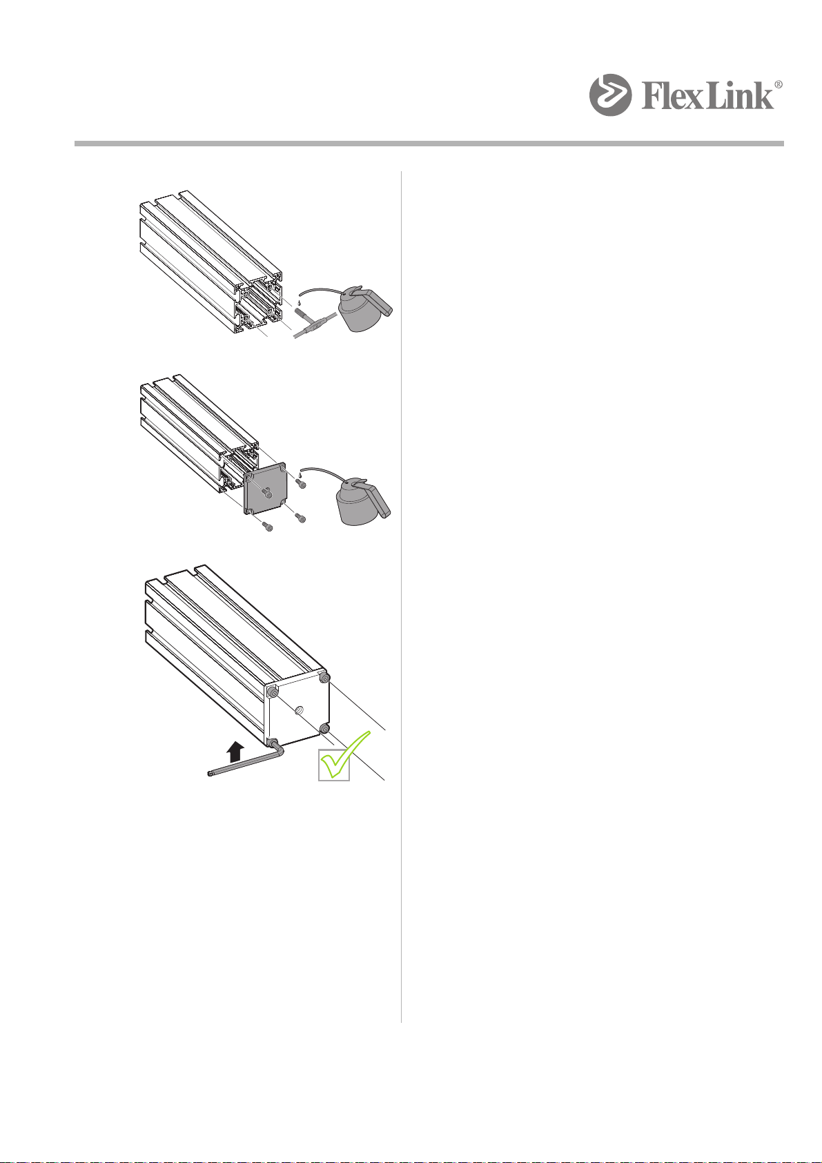
3.3 End plate assembly
5 mm Oil Roller threads
12 X65 System
1
2
3
x4
4x
4x
Created by EBCCW 00:06
13
X65 System
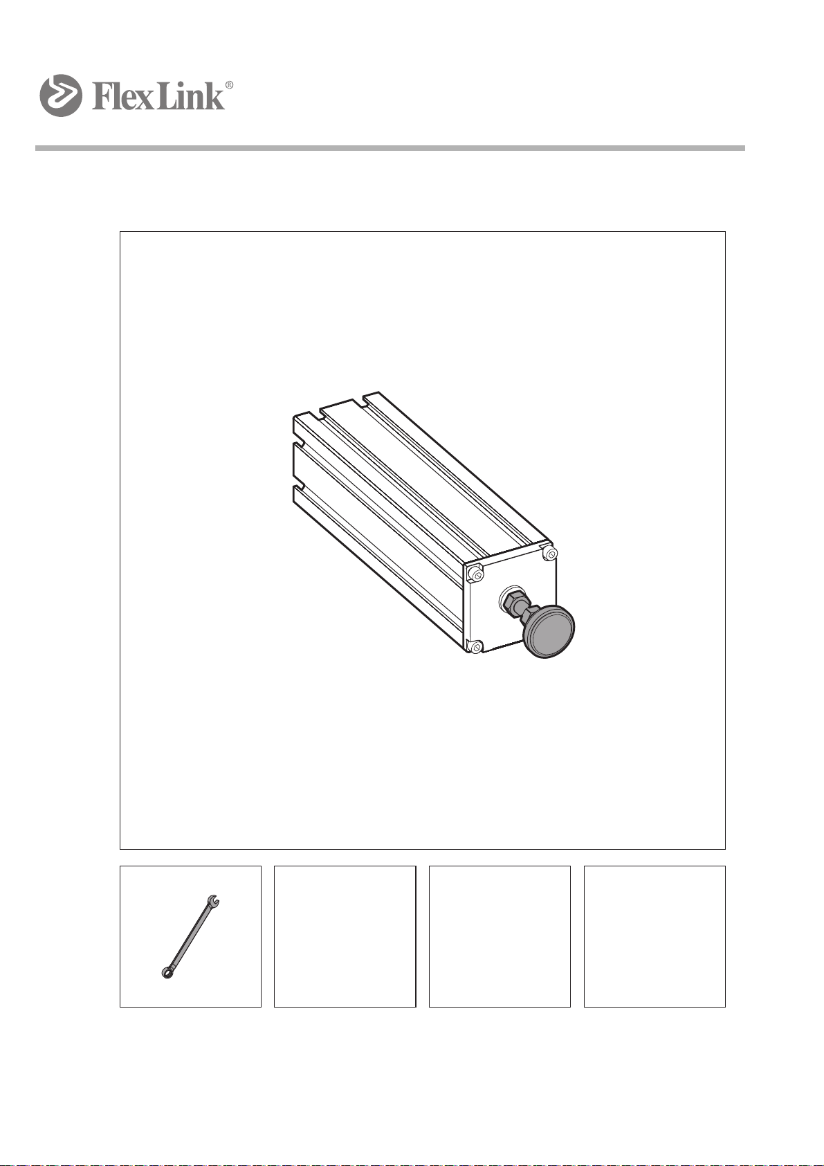
3.4 Adjustable foot assembly
19 mm

14 X65 System
1
2
3
Created by EBCCW 00:06
15
X65 System
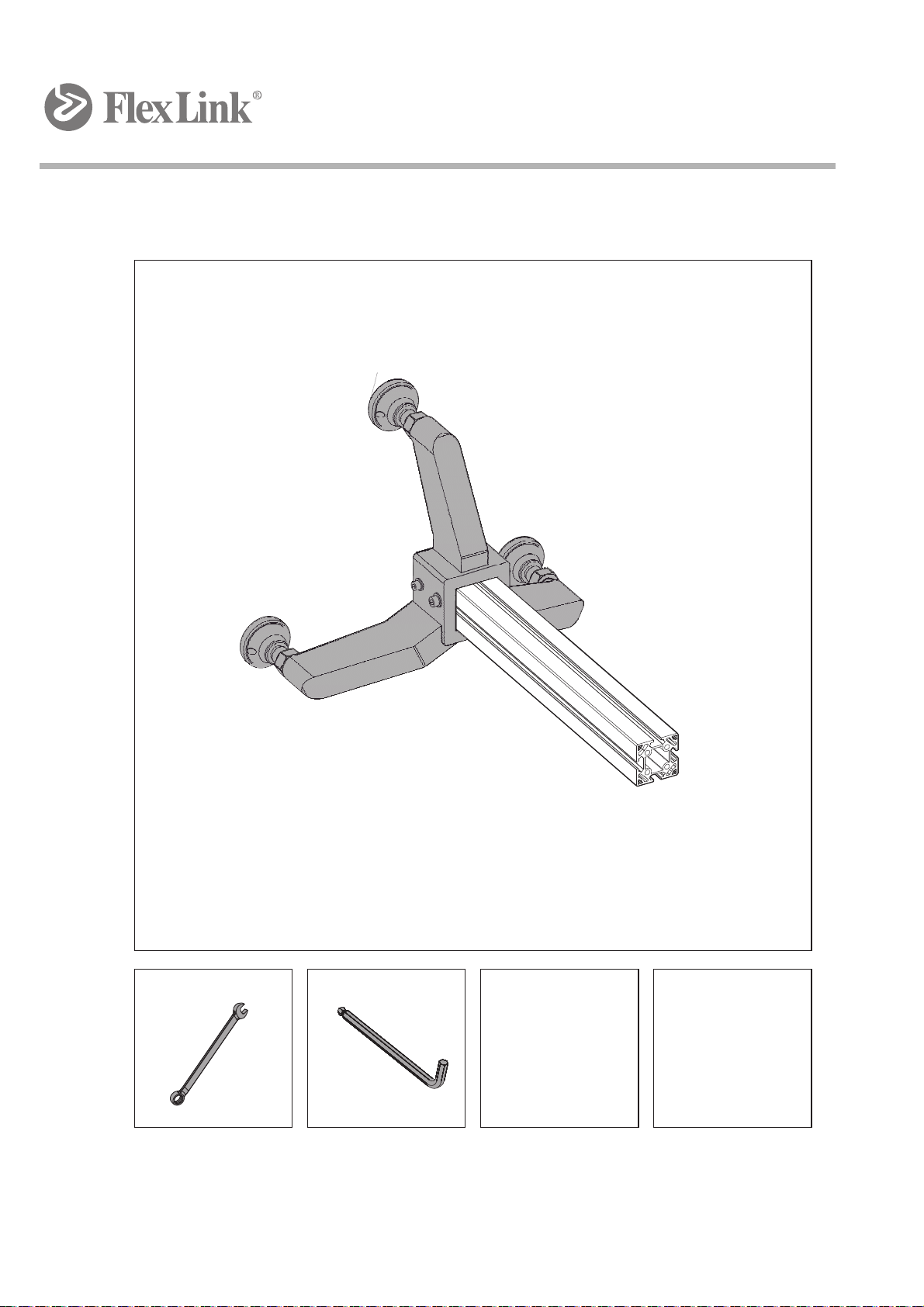
3.5 Three-point support feet assembly
6 mm
30 mm
Table of contents
Other FlexLink Industrial Equipment manuals


