OM0298
September/2020
Page 4of 102
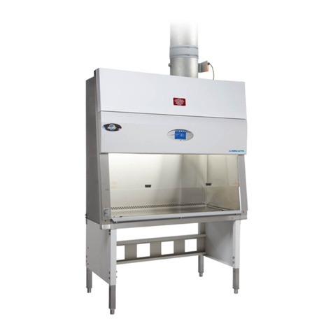
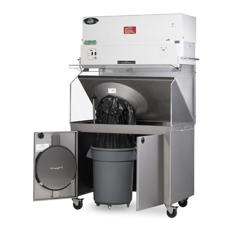
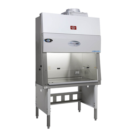
Labgard ES Energy Saver Class II, Type B1
Laminar Flow Biosafety Cabinet
Models NU-427-400E/600E Operation & Maintenance Manual
TABLE OF CONTENTS
Section No. 1.......................................................General Information
Section No. 2.......................................................Models & Features
Section No. 3.......................................................Warranty
Section No. 4.......................................................Shipments
Section No. 5.......................................................Installation Instructions
5.1 ............................................................ Location
5.2 ............................................................ Set-up Instructions
5.3 ............................................................ Exhaust Air Checks
5.4 ............................................................ Certification Testing Methods and Equipment
Section No. 6.......................................................Operating the NU-427E
6.1 ............................................................ Biosafety Cabinet Control
6.2 ............................................................ Operating Guidelines
6.3 ............................................................ Operating Sequence
6.4 ............................................................ Ergonomics
6.5 ............................................................ Cleaning Procedures
6.6 ............................................................ Hazardous Drug Decontamination Procedure
Section No. 7.......................................................General Maintenance
7.1 ............................................................ Decontamination
7.2 ............................................................ LED Lamp Replacement
7.3 ............................................................ HEPA Filter/Motor Replacement
7.4 ............................................................ Sliding Window Replacement & Adjustment
7.5 ............................................................ Airflow Control System Setup & Calibration
7.6 ............................................................ HEPA Filter Leak Test
7.7 ............................................................ Airflow Smoke Pattern Test
7.8 ............................................................ Site Installation Assessment Tests
7.9 ............................................................ Cleanliness Classification Test for Pharmacy Application
7.10 .......................................................... Main Control Board Description & Replacement
7.11 .......................................................... Digital Airflow Sensor Description & Replacement
Section No. 8.......................................................Error Indicators, Troubleshooting, Option-Diagnostics &
Airflow Sensor Performance Verification
Section No. 9.......................................................Remote Contacts
Section No. 10.....................................................Optional Equipment
10.1 ........................................................... Ultraviolet Light
Section No. 11.....................................................Electrical/Environmental Requirements
Section No. 12.....................................................Disposal and Recycle
MANUAL DRAWINGS
ACD-12334.................................................NU-427 Airflow Schematic
BCD-14637.................................................NU-427-400E Specification Drawing
BCD-14638.................................................NU-427-600E Specification Drawing
BCD-11815.................................................Drain Valve Installation
BCD-05572.................................................Butterfly Valve Installation
BCD-05660.................................................Bag-In/Bag-Out Procedure
BCD-05659.................................................Base Cabinet Assembly
ASSEMBLY DRAWINGS
BCD-05147.................................................Base Stand Assembly
BCD-05146.................................................Base Stand Storage Cabinet Assembly
BCD-11817.................................................Control Center & Front Decorative Panel Assembly
BCD-11818.................................................Sliding Window Assembly & Adjustment
BCD-14185.................................................Base Cabinet Assembly
ELECTRICAL SCHEMATICS
CD-000056 (Sheets 1-3) ............................NU-427-400E/600E Electrical Schematic


