PHYWE PJ45 User manual

2INTRODUCTION
Radioactivity is a subject in our society which has been
playing an important role throughout politics, economy and
media for many years now. The fact that this radiation cannot
be seen or felt by the human being and that the effects of this
radiation are not fully explored yet, causes emotions like no
other scientific subject before.
The high-performance diffusion cloud chamber by PHYWE
Systeme GmbH & Co. KG serves for making the tracks of
cosmic and terrestrial radiation visible so that a wide range of
natural radiation types can be identified. Furthermore, the
diffusion cloud chamber offers the opportunity to carry out
physical experiments with the aid of artificial radiation
sources.
3DESIGN AND OPERATION
The cloud chamber consists of a chamber base and the
observation chamber. The chamber base comprises a
cooling element, a power supply, an alcohol reservoir, an
alcohol pump and a programmable time switch. The
observation chamber is placed onto the chamber base.
The bottom of the observation chamber is formed by a
massive, black metal plate (surface 45 cm x45 cm) which is
cooled over the whole surface to about -30°C by means of
the cooling element.
The top plate and the side plates of the observation chamber
consist of two glass hoods which are placed one into the
other. Agrid of fine heating wires (17) is placed between the
upper two glass plates. These wires serve for heating this
area of the chamber thus keeping the hood free from
condensation. At the same time they are held at high voltage
thus generating an electric field that attracts the ions.
09046.90... 99Diffusion cloud chamber PJ45
09046.90… 99/0709
1 SAFETY PRECAUTIONS
•Carefully read these operating instructions completely
before operating this instrument. This is necessary to avoid
damage to it, as well as for user-safety.
•Only use the instrument for the purpose for which it was
designed.
•Check that your mains supply voltage corresponds to that
given on the type plate fixed to the instrument.
•Only use the instrument in dry rooms in which there is no
risk of explosion.
•Do not operate the system when obvious damages or leaks
are visible.
•Install the instrument so that the on/off switch and the
mains connecting plug are easily accessible. Do not cover
the ventilation slots.
•Only use an extension cable or a multiple socket when
absolutely necessary.
• Wait at least 2 hours before putting the cloud chamber into
operation to check that no faults have occurred to the
refrigeration system during transport.
•Always unplug the mains plug before carrying out cleaning
or maintenance work.
PHYWE Systeme GmbH& Co. KG
Robert-Bosch-Breite 10
D-37079 Göttingen
Phone +49 (0) 551 604-0
Fax +49 (0) 551 604-107
E-mail [email protected]
Internet www.phywe.de
Operating instructions
www.phywe.de, © All rights reserved
1
Fig. 1: Diffusion cloud chamber PJ45, 09046.93.
The unit complies
with the corresponding
EC guidelines.

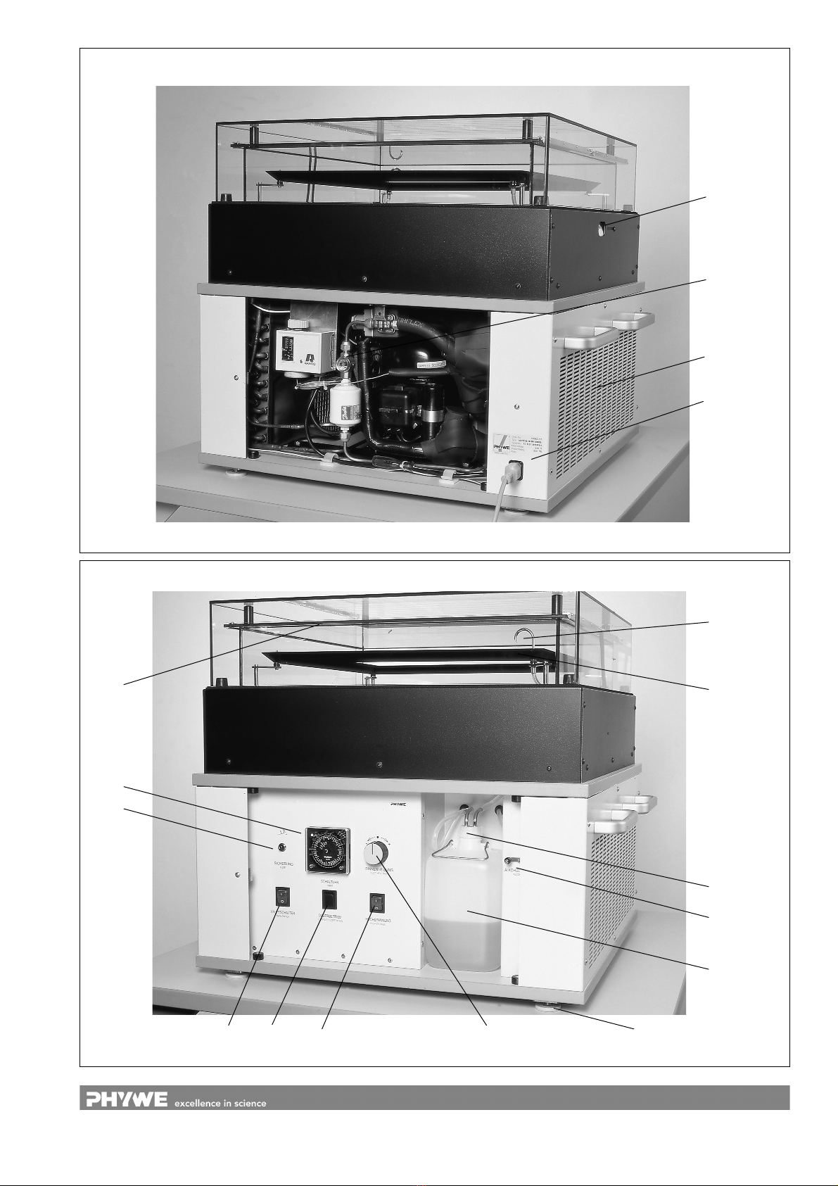
– alcohol reservoir (removable) with a double tubing
assembly which can be screwed off (12)
– main switch (4)
– switch „continuous operation - timer“ (5)
– swtich „high voltage“ (6)
– knurled nut for alcohol supply (11)
– control knob for gutter heating (7)
– programmable time switch (8)
– safety cutout (9)
When you have connected the cloud chamber to mains and
opened the front side, remove the alcohol reservoir (12) from
its installation place and unscrew the union nut (13) of the
double tubing assembly.
Fill the alcohol reservoir three quarters full (see section 7
“Notes on handling iso-propanol”), fit the double tubing
assembly on again and the alcohol reservoir back in place).
Now activate the switches as follows:
main switch (4): ON
mode (5): continuous operation
high voltage(6): ON
The knurled nut (11) serves for regulating the amount of
alcohol dropping into the evaporating gutter. Turn the the
knurled nut to the left and observe the alcohol flowing
through the bended tube (14) and dropping into the gutter.
When the gutter is filled to a liquid level of about 1 cm, reduce
the alcohol supply to about 6 - 8 droplets per second. When
the cloud chamber is being operated, the alcohol in the gutter
should remain constant at this level. After about 5 minutes,
the first white tracks should appear on the black observation
surface. If, however, after 1 hour the tracks become a bit
fuzzy and milky, you have to reduce the gutter heating by
means of the control knob (7).
If the tracks are too weak, the heating of the gutter must be
increased.
If you want to run the cloud chamber at automatic operation,
set the markers of the programmable time switch to the
desired switching time (red marker to switch the cloud
chamber on, green marker to switch it off) and set the mode
switch (5) to „timer“. For more detailed information see the
instructions on the programmable time switch.
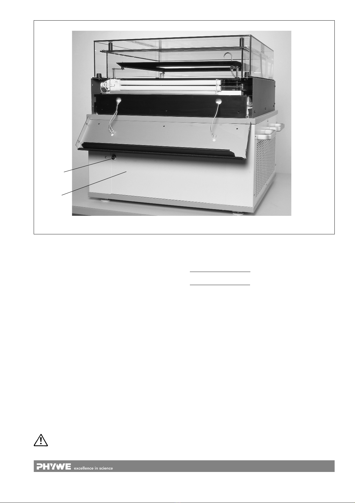
Now close the front side by inserting the plate (3) into the
right side of the opening, pushing it back to the left stop
position and locking it up.
How to open the back side:
Important!
It is only allowed to open the back front. by qualified
personal.The back side can be opened and closed just like
the front side. Here you can see the cooling element, the
thermostat and the inspection glass (21) for the cooling liquid.
During the operation of the cloud chamber the inspection
glass should always be filled with cooling liquid. Make sure
that there are no bubbles in the glass.
The thermostat comes supplied set to the optimum
temperature. In the case of extreme room temperatures, it
might become necessary to modify the setting by turning the
knob on the upper part of the thermostat. Please make sure
that modifications on the cooling element are only
carried out by authorized experts.
The upper part of the glass hood includes an electrically
heated gutter (15) which runs around the whole
circumference. Iso-propyl alcohol flows through a bended
tube (14) and drops into the gutter.
The alcohol evaporates and diffuses from the upper, warmer
area of the chamber to the cold chamber bottom. There the
alcohol is condensed into tiny droplets and flows back into
the reservoir.
Right above the thin liquid layer covering the bottom a zone
of oversaturated alcohol vapour is formed. It’s in this area,
and only in this area, that the charged material particles
coming from the inside or from the outside produce ions
along their trajectory. The tiny alcohol droplets preferably
attach to these ions thus producing a visible cloud track. The
length and the structure of the cloud track give information on
the kind of ionizing particles.
4TRANSPORT OF THE CLOUD CHAMBER
Important!
It is vital to ensure the cloud chamber is not tilted (< 10° from
the vertical) during transport, as otherwise the refrigeration
system will be irreparably damaged.
Transport of a cloud chamber (e.g. change in the place of
installation) should not be carried out with an evaporating
duct full of alcohol. Adrain valve has now been additionally
fitted into the cloud chamber for the draining of the alcohol
from the evaporating duct. This drain valve can be regulated
with a knob which is positioned above the milled screw for the
regulation of the alcohol feed-in (11). Open the drain valve to
allow alcohol to flow back into the alcohol container (12).
Close the drain valve as soon as the evaporating duct is
empty.
5INSTALLATION OF THE CLOUD CHAMBER
In order to guarantee an optimum view on the observation
chamber, it is recommended to place the chamber onto a
square table (border length about 90 to 100 cm) which should
be about 60 cm high. Since the weight of the cloud chamber
is 80 kg, the table must be massive enough to carry this load.
Please make sure that the ventilating slots (19) are not
covered and that the cloud chamber is not subjected to direct
light coming from above. Aslightly darkened room would be
perfect. Use the connecting cable supplied to connect the
cloud chamber to mains. The mains connection (1) is located
down on the back side. The corresponding mains socket
should be protected for max. 16 A.
Adjust the cloud chamber on an absolutely horizontal level
with the aid of the adjustable feet (16) in order to provide an
even alcohol level in the gutter and thus a clear image.
6INITIAL OPERATION
The base of the cloud chamber can be accessed from two
sides. Unlock the lock (2 or 3) to open the two sides, push the
side plate a few centimeters to the right and then carefully
pull it towards you thus lifting it out of the base.
On the front side you can now find a panel with the following
components and operating elements:
www.phywe.de, © All rights reserved 09046.90… 99/0709
2

www.phywe.de, © All rights reserved 09046.90… 99/0709
3
1
19
21
20
Rear view
14
11
16
7654
9
8
17
12
13
15
Front view

The chamber must be disconnected from the mains supply
(by unplugging it!) before the glass covers are taken off for
cleaning.
Cleaning the outer cover:
Simply lift up the outer cover to take it off for cleaning.
Cleaning the inner cover:
Carry out the following succession of steps to take off the
inner glass cover for cleaning:
– Lift the outer cover up and off
– Remove the spacer bolts fitted between the inner and
outer glass covers
– Draw the connecting plug for the cover heating down and
out
– Use the screwdriver provided to unscrew the side plate
– Take out the flat plug for the pane heating (on the side
where the specimen is introduced)
– Take off the inner cover
Removal and re-assembly of the heating wires:
– Disconnect the connecting plug between the two heating
segments
– To linearly expand the heating wires, which are under
mechanical tension, use an external source of current to
electrically heat each of the heating wire segments, one
after the other, with 4.5 V/12 A. When the heating wires
have been slightly lengthened in this way, carefully take
out the track pair of a heating segment from the covering
plate of the cover. Remove the leaf springs between the
tracks and the glass plate.
Artificial radiation sources
On the left side of the chamber base there is an opening (20)
which serves for introducing artificial radiation sources. Use
the head of the screw to push the plate to the right. The ball
with pin which is located behind the plate can be turned
around with the aid of the pin until the opening towards the
inner area becomes visible. Now you can insert an artificial
radiation source like, for instance, the thorium source by
PHYWE a few centimeters into the inner area of the
chamber.
Notes
A: General
To avoid deposits on the inside surface of the inner glass
cover, never disconnect the chamber from the mains supply
nor switch it off at the main switch. This ensures that the
heating circuit for the glass cover heating remains active
even when the chamber itself - controlled by the timer - is
inactive at night or over weekends. In this way, condensation
of alcohol on the inside surface of the inner glass cover, and
the contamination resulting from this, are avoided to a great
extent.
Please read in detail the attached descriptin of the
thermostat.
B: Cleaning
Periodic cleaning of the glass covers with a commercially
available glass cleaning agent is recommended.
Important!
www.phywe.de, © All rights reserved 09046.90… 99/0709
4
Illumination
2
3

Risk phrases: R 11-36-67
Highly flammable. Irritating to eyes. Vapour can make
drowsy and dazy.
Safety phrases: S 7-16-24/25-26-39
Keep container tightly closed. Keep away from sources of
ignition – No smoking. Avoid contact with eyes and skin. In
the case of contact with eyes, rinse immediately with plenty
of water and seek medical advice. Wear eye/face
protection.
First aid: Immediately rinse contacted skin or eyes, with
eyelids open, with plenty of water. On eye injury, seek
medical advice immediately. In case of accident or if you
feel unwell, seek medical advice immediately. After
inhalation: Fresh air, keep airways free. On respiratory
distress: Transport to doctor in half-sitting position.
Waste disposal: Collect combustible halogen-free organic
solvents and solutions in a container labelled for them and
pass to appropriate waste disposal.
8TECHNICAL SPECIFICATIONS
Active layer 45 cm x45 cm xapprox. 1cm
Chamber (B x D x H) 64 cm x64 cm x60 cm
Working liquid 2-Propanol, highest chemical purity
(isopropyl alcohol)
Tank volume 2litres
Illumination Integrated fluorescent lamps
Time switch 7 x 24 hours
(weekly program)
Mains supply
The instrument corresponds to protection class I. It.is only to
be connected to a socket with an earth lead connection.
Connecting voltage see type plate
(+6%/-10%)
Mains frequency 50/60 Hz
Power consumption 900 VA
Fuse see type plate
Weight 80 kg
9CLOUD CHAMBER AND ACCESSORIES
Large Diffusion Cloud Chamber 09046.93
2-Propanol, 1 litre 30092.70
Artificial radioactive sources on request.
The right of technical alterations is reserved.
10 NOTES ON THE GUARANTEE
We guarantee the instrument supplied by us for a period of
24 months within the EU, or for 12 months outside of the EU.
Excepted from the guarantee are damages that result from
disregarding the Operating Instructions, from improper
handling of the instrument or from natural wear.
The manufacturer can only be held responsible for the
function and technical safety characteristics of the
instrument, when maintenance, repairs and alterations to the
instrument are only carried out by the manufacturer or by
– To replace the heating segments, first slide them back on
the glass plate, then again lengthen the wires of the
heating segments with an external source of current (as
described above), so that finally the leaf springs can be
inserted between the tracks and the edge of the glass
plate to maintain the necessary mechanical tension in
the heating wires.
Important!
Because of unavoidable size tolerances in the covering glass
plate, it is absolutely necessary to ensure that each of the two
heating circuits is replaced in its original position.
Assembly
After cleaning the glass covers, replace them in the same
way as they were taken off, but in the reverse order.
C: Changing lamps
Important!
Disconnect the chamber from the mains supply (disconnect
the mains plug!) before changing lamps.
To replace a blown lamp, unscrew the side cover plates with
the screwdriver provided. After lamp replacement take care
that the grounding conductor is properly connected when
screwing the side cover plates back on.
D: Alcohol consumption
The cloud chamber consumes very little alcohol, but despite
of this, the stock of alcohol and the dropping speed should be
regularly checked, in particular when the chamber is in
permanent operation or in regular use with a weeklong
programme.
Use exclusively 2-propanol (isopropyl alcohol) for topping
up.
7NOTES ON HANDLING ISO-PROPANOL
The handling of the alcohol iso-propanol (isopropanol, 2-
propanol, propan-2-ol) is subject to the same rules for the
avoidance of danger as is the handling of other chemicals,
reagents and dye solutions. It is natural that such substances
must be handled cautiously and carefully so that neither
students and teachers nor others are exposed to
unnecessary health hazards.
When handling iso-propanol, therefore, the directions must
be observed that are given in the current up-dated data sheet
(acc. to EC Directive 91/155/EEC), the valid accident
prevention regulations and the directions that apply to the
particular workplace.
Some of the most important handling regulations and general
rules of behaviour are named here without any claim to
completeness:
2-Propanol is a clear, highly flammable and somewhat oily
liquid with an odour that is reminiscent of a mixture of
ethanol and acetone. It mixes in all proportions with water
and most organic solvents. The vapour from iso-propanol
can form explosive mixtures with air.
www.phywe.de, © All rights reserved 09046.90… 99/0709
5

personnel who have been explicitly authorized by him to do
so.
11 WASTE DISPOSAL
The packaging consists predominately of environmentally
compatible materials that can be passed on for disposal by
the local recycling service.
Should you no longer require this product, do
not dispose of it with the household refuse.
Please return it to the address below for proper
waste disposal.
PHYWE Systeme GmbH& Co. KG
Abteilung Kundendienst
Robert-Bosch-Breite 10
D-37079 Göttingen
Phone +49 (0) 551 604-274
Fax +49 (0) 551 604-246
6
www.phywe.de, © All rights reserved 09046.93… 99/0709
Table of contents
Other PHYWE Laboratory Equipment manuals
Popular Laboratory Equipment manuals by other brands

Thermo Scientific
Thermo Scientific Nicolet iS50 GC-IR user guide

Renfert
Renfert Bijou 90 Series instruction manual

OKW
OKW STAR-KNOBS Series Assembly instruction

BIO RAD
BIO RAD BioLogic Duo-Flow Starter Kit Instructions

Sensia
Sensia MS-53 Operating, installation & maintenance manual

Sakura
Sakura Cyto-Tek 2500 operating manual