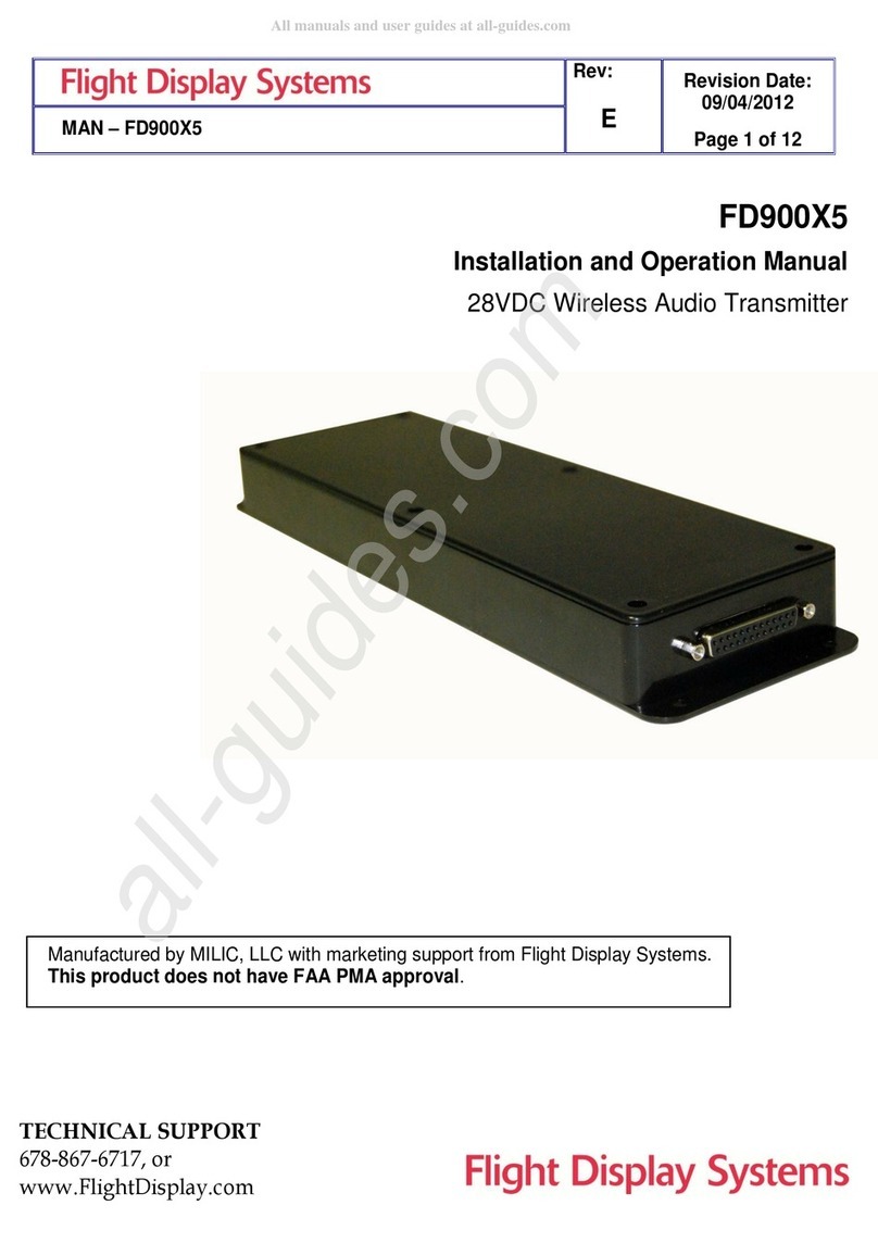
Flight Display Systems FD900X3B User manual

Document Number:
MAN – FD900X3B Ver B
Rev:
A
Revision Date:
02/02/2011
Page 1 of 11
FD900X3B Ver B
Installation and Operation Manual
28VDC Wireless Audio Transmitter
TECHNICAL SUPPORT
678-867-6717, or
www.FlightDisplay.com
All manuals and user guides at all-guides.com
all-guides.com

Document Number:
MAN – FD900X3B Ver B
Rev:
A
Revision Date:
02/02/2011
Page 2 of 11
FD900X3B Ver B
28VDC Wireless Audio Transmitter
© 2006 Flight Display Systems. All Rights Reserved.
Flight Display Systems
1765 Grassland Parkway
Alpharetta, GA 30004
678-867-6717 Phone
678-867-6742 Fax
www.flightdisplay.com
For the most current copy of all product manuals, please visit our website at
www.flightdisplay.com
All manuals and user guides at all-guides.com

Document Number:
MAN – FD900X3B Ver B
Rev:
A
Revision Date:
02/02/2011
Page 3 of 11
Table of Contents
General Information......................................................................................................................4
1. Top View ............................................................................................................................4
2. Additional Information....................................................................................................4
Specifications................................................................................................................................5
Installation Instructions .............................................................................................................5
1. Power ..................................................................................................................................5
Audio Wiring Suggestions.........................................................................................................6
1. Wiring .................................................................................................................................6
2. Power/Video .....................................................................................................................7
Operations Instructions ..............................................................................................................8
Technical Support........................................................................................................................8
Instructions for Continued Airworthiness .............................................................................8
Technical Drawing.......................................................................................................................9
Warranty ......................................................................................................................................10
Log of Revisions.........................................................................................................................11
All manuals and user guides at all-guides.com

Document Number:
MAN – FD900X3B Ver B
Rev:
A
Revision Date:
02/02/2011
Page 4 of 11
General Information
The FD900X3B Ver B is a Wireless Audio Transmitter that represents a state of the art
audio experience. The FD900X3B Ver B has features that allow installation in the smallest
of mounting areas with the minimum of interface equipment. Built with retrofit aircraft
integration in mind, this transmitter can be mounted almost anywhere in the cabin.
Top View
Additional Information
This Wireless Audio Transmitter is for use exclusively with the FD24X3B Headset (not
included, shown below). The headset operation information is included with the purchase
of a headset. A brief overview of headset operation is to turn the headset ON using the
slide ON/OFF switch. Press the TUNE button to tune in the first clear frequency. Adjust the
VOLUME with the volume adjustment wheel. Subsequent channel selections are obtained
by pressing the TUNE button.
FD24X3B
All manuals and user guides at all-guides.com

Document Number:
MAN – FD900X3B Ver B
Rev:
A
Revision Date:
02/02/2011
Page 5 of 11
Specifications
Channels
Three
Channel Frequencies (MHz)
900.44, 918.70, 927.83
RF Output Power
< 10 mW
Total Harmonic Distortion
< 1 %
Signal-Noise Ratio
≥75 dB
Frequency Response
20,000 MHz 30
Dimensions
6.00”(W) x 1.58”(H) x 3.55”(D)
Weight
7 oz
Power
28VDC @ 180 mA
Input
HD-15 Connector
Materials
ABS Plastic (Burn Rating – UL94-5V A)
DO-160 Testing
TBD
Flammability Testing
FAR 25.853(a) Appendix F, Part
I(a)(1)(ii) Passed
Installation Instructions
All cabin entertainment equipment, such as the FD900X3B Ver B, should be installed on a
non-essential bus and have a dedicated circuit breaker. It is a requirement that a switch be
installed in the cockpit so that the pilot can de-energize the entertainment system should it
become necessary.
There are two #8 mounting holes located on the ends of the housing. It is sufficient to
mount by the two attach points. Mounting locations in the cabin can be anywhere that is not
blocked or enclosed by metal surfaces. A drawer, cabinet, headliner or other suitable
location is fine.
When using the headsets, it is necessary to cycle the headset to get the frequency’s to
tune. Sometimes if the operator leaves his/her hands touching the headset the arms and
body will act like an antenna and the tuning is more difficult. For optimum tuning, press the
TUNE button and release.
It is important to match the output impedance of the audio sources. The input of the
FD900X3B should be low level audio such as that used for the inputs to home or
automotive entertainment systems. If one source is significantly stronger than another, it
will cause significant variation in the volume levels between channels. It may also cause
frequency bleeding and crossover between the audio channels.
Power
The FD900X3 Ver B is a 28VDC device that requires 0.1 Amps of power to operate.
All manuals and user guides at all-guides.com

Document Number:
MAN – FD900X3B Ver B
Rev:
A
Revision Date:
02/02/2011
Page 6 of 11
Audio Wiring Suggestions
The center conductor of coaxial cable should be high, and outer shield should be the
return/low.
Avoid routing audio wiring parallel to:
•AC wiring
•Strobe wiring
•DC motor supply cables
•Inverter cabling
•Or any other potential noise source.
Wiring
Recommended cable for audio purposes is PIC 75 Ohm Coax, P/N V75268. This is a
lightweight, flexible, and low signal loss cable which meets FAA flammability requirements
of FAR 23.1359(d), FAR 25.853(a) and FAR 25.869(a)(4).
Similar aviation coaxial cable can be used from other vendors, as well.
All manuals and user guides at all-guides.com
all-guides.com

Document Number:
MAN – FD900X3B Ver B
Rev:
A
Revision Date:
02/02/2011
Page 7 of 11
Power/Video
Pin out for P1 (High Density DB-15 Receptacle)
Part Numbers for DB-15 connectors, manufactured by Tyco or Amp.
High Density, D-sub, 15 contact receptacle (female) P/N 748565-1
HD15F pins P/N M39029/57-354
Pin
Number
Description
1
28VDC Power
2
N/C
3
Audio #1 - Left
4
Audio #1 – Ground (L/R)
5
Audio #1 - Right
6
28VDC Ground
7
N/C
8
Audio #2 - Left
9
Audio #2 – Ground (L/R)
10
Audio #2 - Right
11
N/C
12
N/C
13
Audio #3 - Left
14
Audio #3 – Ground (L/R)
15
Audio #3 - Right
All manuals and user guides at all-guides.com

Document Number:
MAN – FD900X3B Ver B
Rev:
A
Revision Date:
02/02/2011
Page 8 of 11
Operation Instructions
The passengers will be able to access the different audio channels by momentarily
pressing the TUNE button found on the headset (not supplied). It is necessary to cycle the
headset through the different frequencies once turned on so that it may recognize the
transmitting frequencies.
If you recognize degradation in the quality of your audio or that you cannot channelize the
frequencies, check to make sure your headset batteries have sufficient power.
Technical Support
Should you have any questions concerning this product or other Flight Display Systems
products, please contact our Product Support representatives at (678) 867-6717.
Flight Display Systems
1765 Grassland Parkway
Alpharetta, GA 30004
Phone: 678-867-6717
Fax: 678-867-6742
For further product information, technical data and sample wiring diagrams, please click on
the Dealers section of our web site at www.flightdisplay.com
Instructions for Continued Airworthiness
The FD900X3B Ver B is designed not to require regular general maintenance.
All manuals and user guides at all-guides.com

Document Number:
MAN – FD900X3B Ver B
Rev:
A
Revision Date:
02/02/2011
Page 9 of 11
Technical Drawing
All manuals and user guides at all-guides.com

Document Number:
MAN – FD900X3B Ver B
Rev:
A
Revision Date:
02/02/2011
Page 10 of 11
Warranty Information
Flight Display Systems warrants the FD900X3B Ver B against material or manufacturing
defects for a two-year period. Effective 1/1/2009, all equipment sold after 1/1/2009 will have
a 2-year warranty. Warranty begins on date of installation. *The warranty registration card
must be returned upon installation in order to validate the two-year warranty. Any warranty
registration not returned during this time period will default to the date of purchase as the
warranty start date.
If product support is required, please call our Technical Support team at 678-867-6717 to
obtain assistance. If the return of the unit to the factory is required, an RMA number will be
issued at that time. Flight Display Systems will, upon receipt of the failed hardware,
remanufacture or replace the unit at our discretion.
Flight Display Systems will pay Ground Shipping charges for warranted items. Charges for
express shipment will be the responsibility of the sender.
This warranty is not transferable. Any implied warranties expire at the expiration date of this
warranty. We shall not be liable for incidental or consequential damages.
This warranty does not cover a defect or failure that has resulted from improper or
unreasonable installation, use or maintenance, as determined by Flight Display Systems.
This warranty is void if there is any attempt to disassemble or open this product without
factory authorization.
Any labor charges associated with the removal of product or related troubleshooting by a
firm other than Flight Display Systems or its designee will not be covered.
All manuals and user guides at all-guides.com

Document Number:
MAN – FD900X3B Ver B
Rev:
A
Revision Date:
02/02/2011
Page 11 of 11
Log of Revisions
Rev
Date
Page
Description
A
02/02/2011
Initial Release
All manuals and user guides at all-guides.com
all-guides.com
Table of contents
Other Flight Display Systems Transmitter manuals
Popular Transmitter manuals by other brands
M-system
M-system 10TG instruction manual
Thorne & Derrick
Thorne & Derrick KATflow 100 operating instructions
WIKA
WIKA LH-20 operating instructions
Sennheiser
Sennheiser SYSTEM 2020 Instructions for use
Lectrosonics
Lectrosonics HMa instruction manual
R.V.R. Elettronica
R.V.R. Elettronica TEX702TFT Operator's manual
