FLIGHT LINE P-38L LIGHTNING User manual

•
U&erManual
span : 1SDDmm
a.: LW3D1
1
15-27
-

Index
Product Basic Information
Package list
Servo Installation
Installation
:
Power system
L
anding gear
Servo instruction
Integrated circuit module connection diagram
Installing a Battery
Center of Gravity
Control Surface Direction Test
Dual rates
Motor parameters
•Pliqht
EN
2
2
3
7
9
10
11
11
12
12
13
13
14
P-38L LIGHTNING

Introduction C
st
Note:
P-38L LIGHTNING
lt•m Na.: FLW3D1 Pliqh

Product
B
asic
I
nformation
E
E
�
C
(63")
& Note: t
h
e
param
ete
rs
s
t
a
te
d
h
e
r
e
ar
e
d
e
riv
e
d
fr
o
m
te
s
t
r
e
sul
t
s
using
o
ur
acc
e
ss
o
ri
e
s. If you use other accessories, the test results will differ. We cannot
provide Technical Support if you have a problem when using other accessories
Package I ist
2
17gMGx1
4S 2600-4000mAhx2
High speed DIY spare-part
(The following is DIY spare-part, please contact
distributor to purchase separately.)
2-blade propeller spinners
2-b/ade propeller ba
ck
plates
3648-BBOKV brushless motors
2-blade 12x8 propellers
Different equipment include different spareparts. Please refer to the following contents to check your sparepart list.
1
4
P-38L LIGHTNING

S
ervo Installat
i
on
Install main wing servos
0
======================
F
I
y
'
0 w'
,�
. g
<!
(In
Install horizontal tail servos
1.Use a servo tester or your radio to center
the servo. (As shown in the diagram)
2.Use glue to install the servo on the
horizonal stabilizer and elevator horn to the
elevator.
3. Attach one end of the pushrod into the
hole of the servo arm and adjust its length,
keeping the elevator centered and snap the
clevis over the ball link in the elevator's
control horn.
P-38L LIGHTNING
lt•m Na.: FLW3D1
Ph •

Install
i
n
g
S
ervos
Installin
g
vertical stabili
z
er servos
h
y
A
z
A
'
-
Rudder push rod size
Install the nose door servo
Install t
h
e nose
h
atc
h
door
k
m
y
e
k
m
y
D
Rudder pushrod mounting hole
? J • !
P-38L LIGHTNING
Adjusting the Nose hatch door pushrod size
Nose
hatch
door
pushrod
size

Install
i
n
g
servos
Install the nose steering servo
1. Use a
S
ervo testor to center the
servo.
2. Use glue to attach the servo to
the servo fixed
b
ase.
Install the nose steering servo
MG
S
m
m
m
w
w
c
I
Q
Install the main landing gear hatch door
1. Use a servo tester to center the
servo.
2. Use glue to attach the servo to
the servo fixed
b
ase.
3.
Use the two screws to secure
the servo to the servo fixed
b
ase
1.
lnstall the main gear hatch doors (B) to the
hatch door
fixed pins (A).
2.
Insert the left/right hatch door pushrods to the
same
arm hole of servo (D), and snap the
clevis
ends to the ball links of the hatch doors.
3.
Use your radio to test the closed position of
the doors. Adjust the length of the rear hatch
door pushrods to adjust the doors for the best
closed position.
4.
Repeat these steps for the main gear doors
on the second boom.
H
H
Rear hatch door push rod size
Rear hatch door push rod installation hole position 0
�
,.
Pliqh •
Servo arm swivel lock.
A - 9g plastic servo
B - Servo fixed base
C - Screw (PWA2x8mm)

A
ss
emb
l
y
0
•Pliqht
Step 1
Step2
Step 3
P-38L LIGHTNING

Installation
Sl
o
t
Cover
C
Step4
Step 5
Use the 5 screws to secure the gondola to the under surface of main
wing center section. Run all extension wires, through main wing slot and
feed into the tail of the gondola. Finally, plug the extension wires into the
integrated circuit module and ensure that they are plugged into the
correct inputs, refer to the mapping on the circuit module.
A !
(PM3x8mm 2pcs) _ i
Step 7 Step 8
P-38L LIGHTNING
lt•m Na.: FLW3D1
Step 7
Pliqh
Insert the outer main wings to the support rods from
the booms and connect the servo and LED wires to
the extension wires from the booms, then, using 2
(PM3x8mm) screws, attach the outer wings to the
booms.
to

Install
i
n
g the
power system
A-Screw (PA2.3x16mm 6pcs)
B-Scale propeller (12x7, 3-blade Standard prop./Reverse
prop. )
C-Scale propeller back plate
D-Screw (PM3x10mm 1pcs)
E-Spinner (scale 3-blade spinner)
F -Propeller lock bolt
G-Washer (<ll14x1 .5x<P6.2mm)
A
k
k
t
-
We have an optional 2 blade high power system for the
airplane which will improve the performance, Contact you
Distributor for more information or to purchase it..
•Pliqht
\E
\
, as in the
diagram
P-38L LIGHTNING

Landing Gear Assembl
y
Nose Gear Assembl
y
A
Accessories
v
•
�
K
Main Landing Gear Assembl
y
A
Accessories
v
EN
I
' '
P-38L LIGHTNING
Pliqh •

Servo introduction
A servo or reversed servo is defined as follows:
When the servo input signal changes from 1000ųs to 2000ųs, The
servo arm rotates clockwise, its a positive servo. If it rotates
counter clockwise, its a reversed servo.
No.
2
4
N
Servo connection instruction
1.
Using the extension wires, plug the rudder and elevator
servo into receiver.
2.
Run all the other servos and LED lights, through the
extension wires and insert them into the lntegrated
circuit module
Integrated circuit module connection diagram
Use integrated circuit module
As shown in the diagram, connect the extension wires to the designated inputs.
Then connect the aileron, flap and landing gear outputs from the integrated
circuit box to the receiver .
lntergrated circuit module operation
The integrated circuit module servs two functions:
1.
It replaces the Y-wires and other connection cables, it makes the cockpit
imore neat and organized and increases the cable's connection quality.
2.
Through the integrated circuit module design, the landing gear, cabin
door, LED lights are controlled in a single box.
•Pliqht
Landing-GearO
•
•
� •
� •
•
�
•
• •
• •
• •
• •
• •
• •
RECEIVER
-1
•
•
•
• •
P-38L LIGHTNING

Installin
g
a battery
Before connecting the batteries to the ESC's, please
power up your transmitter and make sure the throttle
stick is in the lowest position.
Before connecting the batteries, ensure that nothing is
in the propeller arc or in front of the airplane in order
to avoid accidents and injuries.
-
EN
• ;
Battery Hatch Size: W=62/68mm, H=41/52mm,
L=183mm
The battery capacity and discharge rate we
advise is the following:
4S 14.8V 3300mAh - 4S 14.8V 4200mAh
Discharge rate of C
�
30C
Center of Gravity
T
(
)
65mm
(2-9/16")
P-38L LIGHTNING
lt•m Na.: FLW3D1
r
Pliqh •

Control direction test N
j
Aileron
Stick Left
Elevator
Up Elevator
Rudder
Stick Left
Optional Flaps
Flaps down
Dual Rates
•
•
Stick Right
Down Elevator
Stick Right
•
L
j
P-38L LIGHTNING

Dual Rates
IH2
'
Low Rate
High Rate
Flight setting instructions
'
:
b
0
Motor Parameters
Unit: mm Unit: mm
3748-600KV / 3648-880KV
600RPM/V
880RPM/V
R_J�l
8.8
Unit: mm
P-38L LIGHTNING
lt•m Na.: FLW3D1
\
3748-600KV 3648-880KV
Pliqh •

IH
rs
!
3 !
!
n*m
•Pliqht P-38L LIGHTNING

117g/dm2
�m,:
L
31sog
EPO
m � :
LE D �LED
12x8 L
i
1 �Bm
i�B
P-38L LIGHTNING
lt•m Na.: FLW3D1
Pliqh •

�UR
9 •
•Pliqht
0
iJWlem
=
0
. g
�
4 ··@
<!
'�
P-38L LIGHTNING

P-38L LIGHTNING
lt•m Na.: FLW3D1
s -
C - W
�@:01.5mm
D
aemt IHL
!'t� i-.
.
4 @
Pliqh •

I
c -
•Pliqht
,.
P-38L LIGHTNING
Table of contents
Languages:
Other FLIGHT LINE Toy manuals

FLIGHT LINE
FLIGHT LINE FLW203 User manual
FLIGHT LINE
FLIGHT LINE Fw190 D-9 Dora User manual
FLIGHT LINE
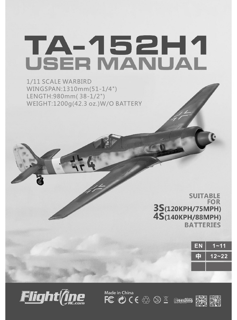
FLIGHT LINE TA-152H1 User manual

FLIGHT LINE
FLIGHT LINE SPITFIRE MK.IXC User manual
FLIGHT LINE
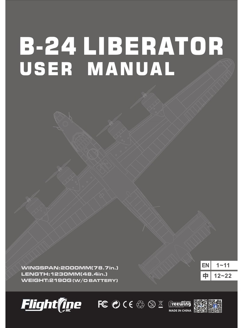
FLIGHT LINE B-24 LIBERATOR User manual
FLIGHT LINE
FLIGHT LINE F7F TIGERCAT User manual
FLIGHT LINE
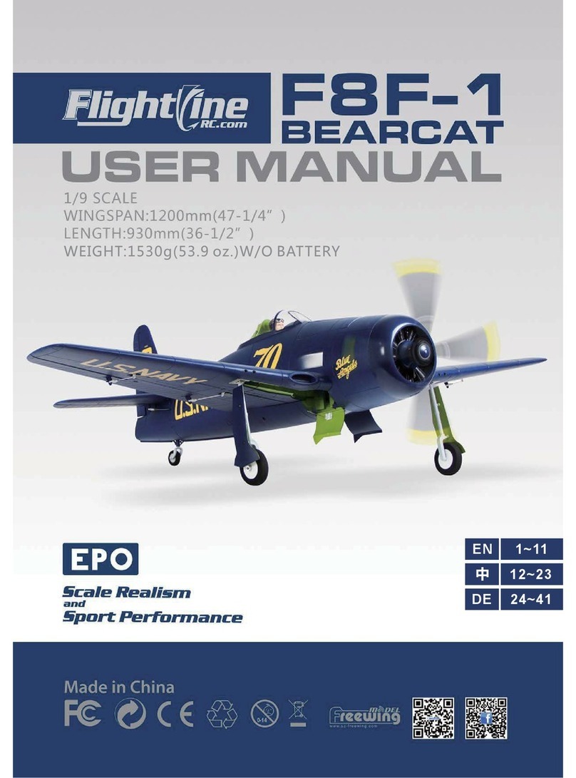
FLIGHT LINE F8F-1 User manual

FLIGHT LINE
FLIGHT LINE B-25J User manual
FLIGHT LINE
FLIGHT LINE SUPERMARINE SPITFIRE MK.IXc User manual

FLIGHT LINE
FLIGHT LINE B-24 LIBERATOR User manual
