FLIGHT LINE SUPERMARINE SPITFIRE MK.IXc User manual

SUPERMARINE
1/7 Scale WWII Warbird
SPITFIREMK.IXc
User Manual
EN
中
1~12
13~24
WINGSPAN : 1600MM (63”)
LENGTH : 1350MM (53.1”)
WEIGHT : 2850G ( W/O BATTERY )

Catalog
前言
产品基本参数
产品包装清单
PNP组装
机身组装
平尾组装
平尾、垂尾钢丝安装
主翼钢丝安装
主翼组装
舵面控制钢丝尺寸
装饰件安装
集线盒使用说明
电池安装说明
重心示意图
舵面测试
大、小舵参数及飞行注意事项
配件说明
舵机使用说明
电机参数
动力系统的安装
前起落架组装
后起落架组装
13
14
14
15
15
15
16
16
17
18
18
19
19
20
21
22
22
23
24
24
Introduction
Basic Information
Package List
PNP Install Insturctions
Install Fuselage
Install Horizontal stabilizer
Install Elevator/rudder
Install Aileron pushrod
InstallMainwing
Pushrod instructions
Install decorated part
Control board use introduction
Install Battery
Center of gravity
Control direction test
Dual Rates and Flight Attention
Accessories Description
Servos Introductions
Parameter of motor
Install power system
Install nose landing gear
Install rear landing gear
1
2
2
3
3
3
4
4
5
6
6
7
7
8
9
10
10
11
12
12

中文版
1
SPITFIRE MK.IXc
Iten No.: FLW303
Thank you for purchasing the FlightLineRC 1600mm Spitfire Mk.IXc!
FlightLineRC is a leading brand produced by Freewing Model in partnership with Motion RC! We
will bring you a new series of propeller driven aircraft at the same level of quality and value you trust
from Freewing Model’s EDF aircraft and other products. FlightLineRC inherits Freewing’s goals of
outstanding innovation, exquisite design, high quality, unbeatable value, and dependable
performance.
The Supermarine Spitfire is one of the most popular warbirds in history. This British single-seat
fighter was used famously by the Royal Air Force and the Allies, earning distinction during the Battle of
Britain and throughout World War II. Over 20,300 aircraft were produced with more than 24 variants.
The Spitfire’s versatility and maneuverability made it a lethal aircraft against Axis forces. The Spitfire
continues to fly in modern times as a tribute to aviation history and military veterans.
This FlightLineRC Spitfire Mk.IXc is approximately 1/7 scale, with a 1600mmm wingspan and
1350mm length. It is molded from EPO foam, featuring a scale shape and smooth surface. The main
wing is assembled from hollow parts and an interlocking plywood and carbon fiber frame, providing
lower weight and higher strength than a solid foam wing. The main wing and horizontal tail are attached
with screws for very convenient transport. Proper ventilation is also designed to keep the electronics
cool. The large battery hatch and removable battery bay floor provides easy access to an organized
battery and receiver compartment.
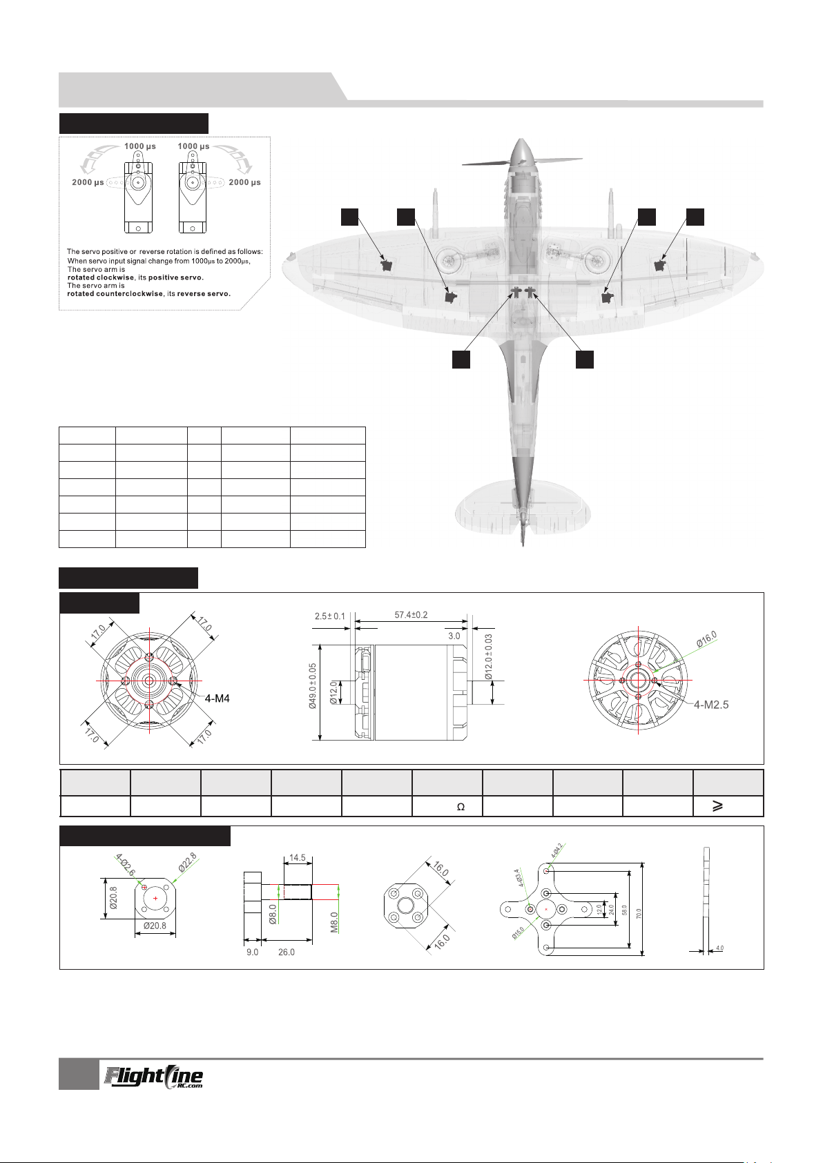
The stock PNP version is equipped with a 5055-390KV brushless outrunner motor and scale 4-
blade propeller and 80A ESC. With the recommended 6S 4000-5000mAh lipo battery, the Spitfire
MK.IXc has a level top speed of 125kph/75mph, with tall vertical power and 4-8 minutes of flight time
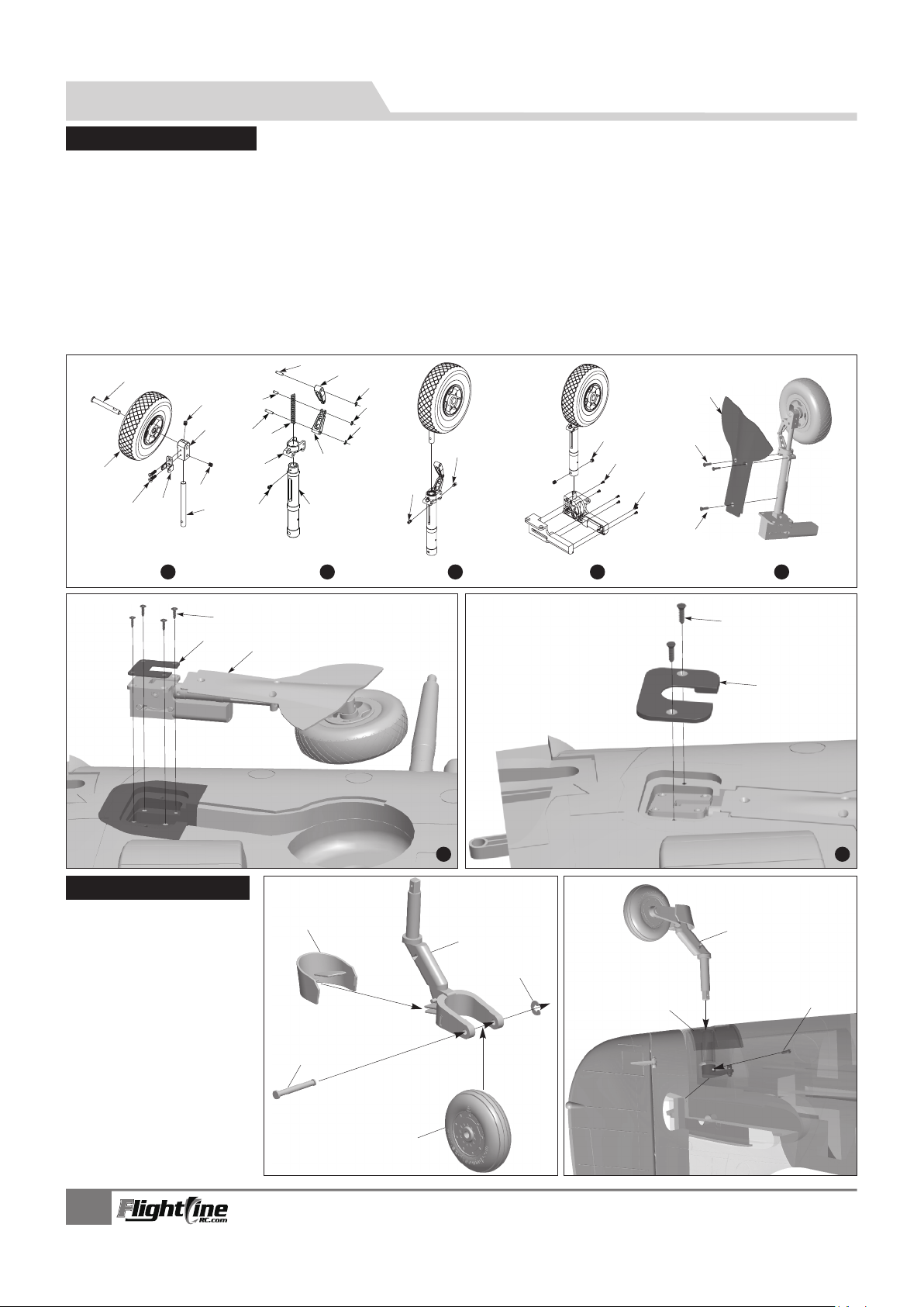
depending on throttle management. To enhance grass performance, the main landing gear use shock
absorbing Oleo struts, a main wheel diameter of 85mm, and a tail wheel diameter of 45mm. Metal
reinforcement plates, thick steel strut pins and axles, and metal trunions work together with the
suspension struts and soft wheels to dampen the forces caused by operating this aircraft on rough
runways. The FlightLineRC 1600mm Spitfire Mk.IXc was optimized for very gentle handling, suitable
for intermediate pilots and above. The Take off, flying performance, and slow speed handling is
especially stable. A very predictable stall and power on recovery make the aircraft easy to control
throughout any aspect of flight. Bright LEDs also aid in visibility of this large and beautiful foam electric
model aircraft.
The FlightLineRC 1600mm Spitfire arrives completely painted and with national insignias pre-
applied. To personalize your Spitfire, included in the box are two optional decal sets, depicting the
aircraft of Squadron Leader F.A.O. Tony Gaze (MA621 DV-A) and Lieutenant Michel Boudier (BS383
GW-Z).
Introduction

2
Wing loading: 74g/dm²
Wing area:46.5dm²
Motor: 5055-390KV
brushless outrunner motor
Propeller : 4-Blade 16×10
ESC: 80A (1pcs)
Servo: : 17g MG×6pcs
Weight: 2850g (W/O battery)
Aileron: Yes
Elevator: Yes
Steering pushrod : Yes
Flap: Yes
LED lights:Yes
Cabin door: Yes
Landing gear: Retract landing gear
Material: EPO
1600mm
(63")
1350mm(53.1")
EN
Product basic information
Package list
1
2
3
4
5
6
PNP ARF Plus Airframe PNP ARF Plus Airframe
7
8
9
10
11
12
No. Name No. Name
Fuselage
Main wing
Horizontal tail
Vertical tail
Decorated part
Spinner
Pre-installed all
electronic parts
Pre-installed all
electronic parts
Pre-installed all
electronic parts
Pre-installed all
electronic parts
Pre-installed
servo
Pre-installed
servo
Pre-installed
servo
No electronic
equipment
No electronic
equipment
No electronic
equipment
No electronic
equipment
Pre-installed
servo
Scale propeller
Carbon tube
Linkage Set
Glue & Non-slip mat
Manual & Decals
Screw&Plastic fo
SPITFIRE MK.IXc
Iten No.: FLW303

PNP lnstall instructions EN
3
1.Use servo tester or radio to center the servo.
2.Use screws to fix the servo on the plastic board.
3.Place the servo cable from the plastic board to
the battery compartment.
Note: If you don't choose the factory servo, the
servo maybe don't fix since of its servo different size.
If like that, we need to remove the fixed wood piece,
and glue the servo in the servo position in fuselage, it
also can use in common.
A
B
C
A-
B-
C-
Screw (PWA3x8 4pcs)
17g servo
Servo mount
1. As the photo shown, install the left/right elevator on the tail fuselage.
2.Turn over the fuselage, and use 4 pcs screws to fix the elevator.
SPITFIRE MK.IXc
Iten No.: FLW303
A
C
D
step 3
step 2
step 4
Steering pushrod
(710mm)
Elevator pushrod
(760mm)
1. Insert one side of elevator pushrod A ,through plastic tube B, to the servo arm C.
2.Buckle the ball head buckle of elevator pushrod to the rudder horn D.
B
Install fuselage
Note:There is a EPO glue on package,
Please use it to glue.Glue should be
spread evenly and wait for 90 seconds.
Then install on, its best glue condition.
1. Before installation, remove the battery compartment and fuselage pushrods in plastic tube,
and install the ball-head buckle on the pushrods. Then insert the rudder pushrod from tail
fuselage to front fuselage plastic tube.
2. Insert the elevator pushrod from tail fuselage to front fuselage plastic tube.
3. Use epoxy glue to attach the front and rear fuselage. During the gluing process, take special
attention so that NO GLUE enters the control rod tubing! If any glue enters the control rod
tubing, the control rods will not be able to move and the model will be useless. Proper
materials and execution of assembly is the responsibility of the builder and any damage is
not covered by the manufacturer or vendor warranty.
4. Use epoxy glue to attach the foam parts A.B. on the fuselage
step 1
A
B

1.Use servo tester or radio to center the
servo.
2.Use glue to install the servo and aileron
horn on the main wing.
3.Buckle the servo cable to the through,
after installed all the servos, stick on
the decal.
4.One side pushrod insert to the servo
arm, adjust its length. And insert the
Ball-head to the aileron horn.
5.Repeat the above four steps, install the
other side main wing servo and flap servo.
AB
C
D
Step 2
Step 1
Screw
(PWM4x8mm 2pcs)
Servos wire
Carbon tube (Ø10x400mm)
Main wing
Step 3
Control board
InstallMainwing
As the photo shows:
1.Insert the carbon tube to the main wing, and insert the left/right main wing together.
Glue is not required.
2.Use 2 screws to fix the main wing with machine screws.
3.Match the text on the label with the text on the control board, and attach it as shown
in the photo.
SPITFIRE MK.IXc
Iten No.: FLW303
1. Insert one side of rudder pushrod A ,through plastic tube B, to the servo arm C.
2.Buckle the ball head buckle of rudder pushrod to the rudder horn D.
AB
C
D

Step 5
Step 7
Step 6Plastic for A
Plastic for B
Screw
(PWM4x8 4pcs)
Servos wire
Step 4
As the photo shows:
4.Insert the fuselage LED light cable to the control board. Verify the polarity
before inserting. Match the – to -, and the + to +.
5.Pull the main wing servo cable from fuselage up into the battery compartment.
6.Insert the main wing plastic part A, B to the back of main wing surface.
7.At last use 4 pcs machine screws to attach the main wing to the fuselage.
LED light cable
Main wing
Pushrod diameter Ø1.5mm
Steering pushrod size
710mm
(27-15/16")
Pushrod diameter Ø1.5mm
65mm
(2-9/16")
2
3
Pushrod diameter Ø1.5mm
760mm
(29-15/16")
2
Pushrod diameter Ø1.5mm
125mm
(4-15/16)
1
2
3
2
3
4
Pushrod diameter Ø1.5mm
58mm
(2-1/4")
1
2
3
2
3
4
Pushrod instructions
Steering pushrod mounting hole
Rudder pushrod size Rudder pushrod mounting hole
Elevator pushrod size Elevator pushrod mounting hole
Aileron pushrod size
Flap pushrod size
Aileron pushrod mounting hole
Flap pushrod mounting hole
LED light
SPITFIRE MK.IXc
Iten No.: FLW303

Note:After finish the above steps, depending on the mark of control board, insertaileron,flap servo cable and landing
gear cable to the control board.
2.Use 1 pcs screw to fix the intake pipe.
3.Insert the cannon barrels on the main
wing. Glue is not required. This part can
be removed for transport.
Install decorated part
4.Use clear canopy glue to attach the scale rearview mirror on
the clear canopy. Do not use CA glue. CA glue may damage
the clear canopy. Finally, insert the antenna into the top of the
fuselage. Glue is not required. This part can be removed for
transport.
Cannon barrels
Rearview Mirror
Use Control board
Control board operation
Through control board,thelandinggear,cabindoor,LEDlight
controlledinunified.
SPITFIRE MK.IXc
Iten No.: FLW303
Control board
control board

PNP lnstall instructions EN
7
Before connect the battery and receiver, please switch
on the transmitter power and make sure the throttle stick
is in the lowest position.
After connecting your receiver and plugging in the battery for
the first time, before please make sure that the propeller is
not attached. After you have programmed your radio transmitter,
before all future flights whenever you plug in the battery also
make sure there is no object within the propeller diameter to
avoid accidents and personal injury!
The battery capacity and discharge rate we advise
is in the following:
6S 22.2V 3500mAh ~ 6S 22.2V 5000mAh
>
Discharge rate of C 30C
Battery install on the front of
fuselage, and use magic tape to fix.
Battery cabin size:
L=260 W=76 H=45(mm)
Battery
Cockpit
Velcro
Tape lift up and remove the
battery compartment cover
Install Battery
90mm
(3-1/2")
Center of gravity
SPITFIRE MK.IXc
Iten No.: FLW303

8
Stick Left
PNP lnstall instructions EN
Control direction test
Aileron
Elevator
Rudder
Flaps
Up Elevator
Stick Left
Flaps down
Stick Right
Down Elevator
Sitck Right
SPITFIRE MK.IXc
Iten No.: FLW303

9
PNP lnstall instructions EN
Dual rates
H1
H2
H1
H2
Flight Attention:1.Depending on your flight battery and your personal preference for flight stability versus agility,
trim the elevator 2mm up. This can be pre-set by either of the following two ways:
- Use pushrod to keep 2mm elevator up.
- Center the elevator, and set the 2mm elevator up in your radio.
2.When the flaps are deployed, the aircraft will nose slightly downward. In your radio transmitter,
program a Down-Flap-to-Up-Elevator mix according to these parameters.
- Flap travel down 24mm/ set elevator travel UP 1.5mm
- Flap travel down 40mm/ set elevator travel UP 3mm
Aileron Flaps
Elevator Rudder
Rudder (The Bottom)
H1/H2 27mm/27mm
D/R Rate:75%
H1/H2 28mm/28mm
D/R Rate:80%
H1/H2 33mm/33mm
D/R Rate:100%
H1/H2 33mm/33mm
D/R Rate:100%
Flaps
H1 24mm
H1 40mm
Aileron(Is Side)
Low Rate
H1/H2 31mm/31mm
D/R Rate:80%
H1/H2 38mm/38mm
D/R Rate:100%
High Rate
Elevator (Is Side)
H1
H2
H1
SPITFIRE MK.IXc
Iten No.: FLW303

10
If you need to purchase other brand servo, please
refer to the following list to choose correct size servo.
Position
Aileron(L)
Aileron(R)
Flap(L)
Flap(R)
Elevator
Rudder
1
2
3
4
5
6
Positive
Positive
Positive
Positive
Positive
Positive
550mm
550mm
360mm
360mm
180mm
180mm
12 34
56
5055-390KV Unit: mm
ESC
Item No. KV Value Volate
(V)
Current
(A)
Pull
(g)
Motor
Resistance
Weight
(g)
No Load
Current
390RPM/V 22.2V 60 5600 0.02 410 2.3A/10V 80A
Propeller
4-Blade16×10
Accessories Description EN
Servos Introductions
Model No. Pos./Rev. Cable length
17g Hybrid
17g Hybrid
17g Hybrid
17g Hybrid
17g Hybrid
17g Hybrid
Parameter of motor
Motor size
Motor shaft,X-fixed base
Unit: mm
MO1505501
SPITFIRE MK.IXc
Iten No.: FLW303

11
A-
B-
C-
D-
E-
Screw (KM4x8mm 4pcs)
Motor X-fixed base
5055-390KV out-runner motor
Propeller folder
Screw (HM2.5x10mm 4pcs)
A
C
B
D
A-
B-
C-
D-
Screw (FA3x8mm 4pcs)
Battery tray
ESC
Tray holder
Put the ESC under the battery tray, there
is a special designed ventilation ducts, it
can cool the electric equipment effectively.
Install power system
A
BC
DE
Install on ESC
Accessories Description EN
SPITFIRE MK.IXc
Iten No.: FLW303
A-
B-
C-
D-
E-
F-
G-
Motor fixed mount
Screw (PA4x15mm 4pcs)
Cup head screws (M3x20mm 8pcs)
Locking gasket (M3 8pcs)
Propeller fixed cross
Scale propeller (16x10,4-blade)
Scale propeller fixed plate
A
B
A-
B-
C-
D-
E-
Nose plug
Screw (PM3x30mm 1pcs)
Locking gasket (M3 1 )pcs
Spinner (scale 4-blade spinner)
Propeller fixing bolt
C
D
E
F
G
A
B
C
D
E

12
Step 6
AB
AC
AD
Step 7
AE
AF
A -
B -
C-
D-
E -
F -
G-
H-
I -
J -
K -
Nose gear axle
Nose wheel (Ø85x26mm)
JIMI Screw (M4x4)
Nose gear slant strut
JIMI Screw (M4x3)
Nose gear shock absorber active rod
Nose gear shock absorber arm fixed part
Screw (PM2x3 2pcs)
Pin (Ø3.5x12.6mm 1pcs)
(Ø2x13.1mm 1pcs)Pin
(Ø3.5x7.3mm 1pcs)Pin
L -
M-
N -
O-
P -
Q-
R -
S -
T -
U -
V -
(Ø1.5mm)C-Buckle
(Ø1.5mm)C-Buckle
(Ø1.5mm)C-Buckle
Spring
Nose gear shock absorber scissor arm
Nose strut fixed ring
Screw (PM2x3 1pcs)
Nose gear strut
X Set screw (M3x5.2 2pcs)
IMI Screw (M4x4)
Screw (PA1.6x10 4pcs)
W-
X-
Y-
Z-
AB-
AC-
AD-
AE-
AF-
Screw (PA1.4x12 2pcs)
Nose landing gear door type
Screw (KA2.3x8 2pcs)
Screw (FM2x7 1pcs)
Nose landing gear
Metal reinforcement plate
Screw (KA3x12 4pcs)
landing gear cover
Screw (KA2.3x8 2pcs)
A
B
C
D
EH
G
F
I
A -
B -
C-
D-
E -
F -
G-
H-
I -
Rear wheel (Ø45x16mm)
Rear gear supporting rod
Rear wheel shaft
C-Buckle (Ø5xØ2mm)
Rear wheel fairing
Tail steering arm
Rear gear fixed plastic part
Tail gear set
Screw (PA1.6x6mm)
Step 3
T
T1
I
Step 1
A
C
B
D
E
F
G
H
Step 4
U
V
W
Step 2Step 5
Y
X
Z
J
K
L
M
N
P
P1
O
Q
RS
Accessories Description EN
Install nose landing gear
Please assemble、disassemble the rear landing gear according to the following photo.
Install rear landing gear
1.Refer to the right photo, install
the tail landing gear set.
2.Insert the tail gear set C to the
fixed plastic part B, and
continue to insert to the tail
steering arm A.
3.Use screw D to fix the tail
steering arm.
SPITFIRE MK.IXc
Iten No.: FLW303

前 言 中文版
注意:模型产品是具一定危险性的产品,请禁止14岁以下的儿童玩耍,14 岁以上的儿童,请在有飞行经验的成人指导下使用,无飞行经验的购买者,应当在具有
一定电动涵道飞机飞行经验的成人指导下使用! 组装模型前,请仔细阅读说明书,按照说明书的要求进行安装. 进行调试和飞行时,请根据说明书指示的参数进行调整。
重要提示
1.模型飞机不是玩具,操作者需要具备一定的经验;没有经验的初学者,必须在有丰富经验的专业人士指引下,逐步学习!
2.在组装之前,必须认真阅读产品说明书,严格按照说明书指示操作。
3.飞翼模型及其销售商,对于违反说明书的要求操作而造成的损失、将不负任何法律责任!
4.模型飞机的使用年龄必须是14岁以上的儿童或者成人。
5.此模型产品使用EPO材料制成,表面喷涂油漆,不可随意使用化学制剂擦拭,否则会损坏模型产品。
6.不可以在公共场合、高压线密集区、高速公路附近、机场附近或者其它法律法规明确禁止飞行的场合飞行。
7.不可以在雷雨、大风、大雪或者其它恶劣气象环境下飞行。
8.模型飞机的电池产品,不可以随意乱扔,乱放。存放时,必须保证周边2M范围内,无易燃、易爆物体。
9.损坏或者报废处理的模型飞机电池,应妥善回收处理,不准随意抛弃,避免自燃而引发火灾。
10.在飞场飞行时,应做到妥善处理飞行后所产生的垃圾,不可随意抛弃、焚毁模型及其配件。
11.在任何情况下,都必须保证油门杆处于起始位、发射机处于打开状态时,才能连接模型飞机内部的动力电池.
12.无论是模型飞机是在正常飞行过程中,或者是在缓慢降落过程中,都不要尝试用手去回收模型。必须等模型降落停
稳以后 ,再进行回收!
13
感谢您购买Flightline 1600mm翼展系列二战螺旋桨模型飞机!
Flightline是Freewing旗下的一个全新品牌!将为大家带来全新的、高质量和高体验值的螺
旋桨系列产品!Flightline将继承Freewing在涵道领域中各种优秀的创新思想和精湛的设计,给
大家提供更加细致和优秀的产品体验
超级马林喷火(Supermarine Spitfire)是第二次世界大战时英国皇家空军及部分同盟国使
用的单座位战斗机。是英国在二次世界大战公认最强的单发战斗机。从1936年第一架原型机试飞
开始,经过不断地改良,各种型号的喷火战斗机在整个第二次世界大战期间共生产了20,300架,
精心设计的喷火战斗机,不仅担负英国维持空权的重大责任,同时转战欧洲、北非与亚洲等战
区,提供给其他盟国使用!
FlightLineRC品牌最新1/7比例喷火模型,翼展1600mm,机长1350mm, 外形轮廓逼真,采
用EPO材料制作,产品表面光洁、顺滑。模型的主翼,使用了中间碳纤材料井格设计,在有效减
轻整体重量的同时,极大地增强了主翼的抗扭强度。同时,主翼与平尾,均采用了可拆式螺丝固
定结构,易于维护与运输,使用磁石吸附的电子设备舱盖,可以方便的更换电池和调试电子设
备。机体内部的电池舱,设计了一条通风管道,使电子设备能够有效散热,延长寿命。用螺丝固
定的电池托盘,将电池舱分为上、下二层,方便了连接线的布置及后期的维护。
这款模型采用了高功率的5055-390KV无刷马达,80A ESC,配合四叶仿真桨,使用6S电
池,给我们带来强劲的拉力,最高速度达到125kph/75mph。我们建议使用的电池规格是6S
3500~5000mAh,最高飞行时长分别达到4~7分钟。按真实比例制作的高仿真前后机轮,外径分
别是85mm/45mm,可以适应绝大多数的草场起降环境。这款喷火战斗机模型,起飞过程非常稳
定,飞机的滑跑性能稳定,不易偏向。空中飞行时,飞行姿态与舵面指令之间的回馈效果优秀,
同时,无论是高速还是低速阶段,都拥有极佳的飞行稳定性。
飞机在出厂前,已经喷涂好油漆,并且预贴部份贴纸。在箱子内,包括二套不同编号的贴
纸,您可以根据自己的喜好,选择一款完成剩下的贴纸工作。
SPITFIRE MK.IXc
Iten No.: FLW303

14
中文版
产 品 基 本 参 数
产 品 包 装 清 单
翼载荷:74g/dm²
翼面积:46.5dm²
电机 : 5055-390KV外转无刷电机
螺旋桨 : 4叶 16×10
电调 : 80A 无刷电调
舵机 : 17g铜齿×6pcs
重量 : 2850g (不含电池)
副翼功能:有
平尾功能:有
方向舵: 有
襟翼功能:有
LED灯:有
舱门:有
起落架:电动可收放起落架
机体材料:EPO
注意: 此处各项参数,均使用本公司配件测试得出,如果使用副厂配件,会有所差异。
使用副厂配件时所产生的问题,我们将无法给予技术支持!
1600mm
(63")
1350mm(53.1")
打开产品包装,核对包装清单。
(不同配置的版本,包含内容不同!)
序号 配件名称 PNP ARF Plus Airframe
1
2
3
4
5
6
机身
主翼
平尾
垂尾
装饰件
螺旋桨桨罩
螺旋桨
碳纤管
舵面控制钢丝
胶水、防滑垫
说明书、贴纸
螺丝、塑料件
序号 配件名称 PNP Airframe
7
8
9
10
11
12
预装所有电子设备
预装所有电子设备
预装所有电子设备
预装所有电子设备
ARF Plus
预装舵机
预装舵机
预装舵机
预装舵机
不含电子设备
不含电子设备
不含电子设备
不含电子设备
SPITFIRE MK.IXc
Iten No.: FLW303

中文版
PNP 组装说明
15
SPITFIRE MK.IXc
Iten No.: FLW303
平 尾 、 垂 尾 钢 丝 安 装
1.通过舵机测试仪或者摇控器,把舵机摇臂校
正到居中位置;
2.使用螺丝把舵机固定在塑料板上;
3.将舵机线从塑料板下方,放置到电池舱内。
注意:自选舵机时,可能因为舵机尺寸的关系,无法固定。
此时,我们可以取下舵机固定木片,直接将舵机粘在塑料板下
方的泡沫舵机孔内,不会影响使用;
A
B
C
A-
B-
C-
螺丝 (PWA3x8 4pcs)
舵机
舵机固定座
平 尾 组 装
1.如图所示,将左、右平尾安装在机身尾部上
2.然后使用4颗螺丝固定平尾,防止松脱! 步骤 1
步骤 2
螺丝
(FA3x8mm)
步骤 3
机 身 组 装
注:包装盒内有赠送的EPO胶水,请使用这
支赠送的胶水进行粘合作业。涂摸胶水应该
均匀。胶水均匀涂摸完毕,不要立即粘合,
请等待90秒时间,再进行粘合,效果最佳!
如图所示:
1.安装前,取下电池舱盖和机身吸塑管里面的控制钢丝,然后将控制
钢丝拧上球头扣后,把方向舵控制钢丝从尾部穿入到机身吸塑管内;
2.把平尾控制钢丝从尾部穿入到机身吸塑管内;
3.使用胶水粘合前、后段机体。
4.用胶水将泡沫件A、B粘到机身上。
步骤 1
步骤 2
步骤 4
A
B
C
D
1.将平尾控制钢丝A未装球头扣的一端,通过塑料管B,插入到舵机摇臂C内;
2.将平尾控制钢丝A上的球头扣入平尾摇臂D上。
A
B
方向舵控制钢丝
(710mm)
平尾控制钢丝
(760mm)

16
中文版
PNP 组装说明
主 翼 钢 丝 安 装
1.通过舵机测试仪或者摇控器,把舵机摇臂校
正到居中位置;
2.用胶水分别把舵机和舵面摇臂粘到主翼上;
3.将舵机线卡到舵机线槽内,等所有主翼舵机
安装完成,贴上贴纸;
4.钢丝一端穿入到舵机摇臂后,调节钢丝长度,
在保持舵面居中的情况下,将球头扣入舵面
摇臂内;
5.重复以上4个步骤,安装襟翼舵机和另外一
侧主翼舵机。
AB
C
D
A-
B-
C-
D-
舵机
主翼控制钢丝
舵面摇臂
舵机线
主 翼 组 装 步骤 1
如图所示
1.将碳纤管插入主翼上,然后把左、右主翼对插;
2.使用2颗螺丝锁紧主翼,防止脱落;
3.将集线盒底面贴纸撕开,然后将集线盒粘贴即可;
步骤 2
螺丝
(PWM4x8mm 2pcs)
主翼舵机线
碳纤管 (Ø10x400mm)
主翼
步骤 3
集线盒
注意:安装垂尾舵面控制钢丝时,首先需要确保我们已经将后轮
调试到居中位置;然后再安装垂尾舵面控制钢丝,并通过调节塑料夹
头,使垂直尾翼保持居中位置;
1.用垂尾控制钢丝将转向舵摇臂与垂直尾翼上的舵面摇臂
连接起来!
SPITFIRE MK.IXc
Iten No.: FLW303
1.将方向舵控制钢丝A未装球头扣的一端,通过塑料管B,插入到舵机摇臂C内;
2.将方向舵控制钢丝A上的球头扣入尾舵摇臂D上。
AB
C
D

17
中文版
PNP 组装说明
舵 面 控 制 钢 丝 尺 寸
钢丝直径 Ø1.5mm
方向舵控制钢丝尺寸 方向舵控制钢丝安装孔位
710mm
(27-15/16")
钢丝直径 Ø1.5mm
垂尾控制钢丝尺寸 垂尾控制钢丝安装孔位
65mm
(2-9/16")
2
3
钢丝直径 Ø1.5mm
平尾控制钢丝尺寸 平尾控制钢丝安装孔位
760mm
(29-15/16")
2
钢丝直径 Ø1.5mm
125mm
(4-15/16)
副翼控制钢丝尺寸 副翼舵机钢丝安装孔位
1
2
3
2
3
4
钢丝直径 Ø1.5mm
58mm
(2-1/4")
襟翼控制钢丝尺寸 襟翼舵机钢丝安装孔位
1
2
3
2
3
4
步骤 5
如图所示:
4.把机身背脊LED灯线插入到集线盒上;
5.将主翼舵机线穿入到机身并拉到电池舱内;
6.将主翼固定塑料件A、B分别插到主翼下表面;
7.最后用4颗螺丝固定主翼。
步骤 7
步骤 6塑料件 A
塑料件 B
主翼
螺丝
(PWM4x8 4pcs)
主翼舵机线
LED灯
步骤 4
LED灯线
SPITFIRE MK.IXc
Iten No.: FLW303

18
中文版
PNP 组装说明
装 饰 件 安 装
螺丝
(PWM4x8mm)
机腹进气管
步骤 1步骤 2
1.如图所示,用胶水将散热器A和B粘到主翼下表面。 2.用1颗螺丝拧紧机腹进气管。
步骤 3步骤 4
3.将机枪插入到主翼上。
4.使用胶水将后视镜粘到透明座舱上;
最后把天线插入到机背上。
A
B
A-
B-
散热器(L)
散热器(R)
机枪
天线
后视镜
集线盒使用说明
集线盒的使用
如下图所示,将模型上使用的舵机、起落架、舱门及LED灯按照图示,分别插入
指定的插口内。然后,将集线盒上的副翼、襟翼及起落架输出线,接入接收机。
集线盒的工作原理
集线盒有二个方面的作用:
1.代替Y线及其它连接线,使设备舱显得更加整齐。
同时,提高线路的连通质量。
2.通过集成电路的设计,对起落架、舱门、LED灯进行统一控制。
注意:1.完成以上步骤后,根据集线盒上的内容通道标识,将所有舵机线插入到集线盒内。
SPITFIRE MK.IXc
Iten No.: FLW303
Table of contents
Other FLIGHT LINE Toy manuals

FLIGHT LINE
FLIGHT LINE OV-10 Bronco User manual

FLIGHT LINE
FLIGHT LINE LAVOCHKIN LA-7 FLW202 User manual

FLIGHT LINE
FLIGHT LINE SPITFIRE MK.IXC User manual

FLIGHT LINE
FLIGHT LINE B-24 LIBERATOR User manual

FLIGHT LINE
FLIGHT LINE FLW204 User manual

FLIGHT LINE
FLIGHT LINE TA-152H1 User manual

FLIGHT LINE
FLIGHT LINE P-38L LIGHTNING User manual

FLIGHT LINE
FLIGHT LINE FLW203 User manual

FLIGHT LINE
FLIGHT LINE F7F TIGERCAT User manual

FLIGHT LINE
FLIGHT LINE B-25J User manual