Flintec MCS-64 User manual
MCS-64
(Multi Channel System for Process Industry)
Manual MCS-64 with CANbus
Document no.G164-Rev4-GB
Manual MCS-64 Page 1
www.flintec.com
Exc-
Sen-
Sig-
Sig+
Sen+
Exc+
Exc-
Sen-
Sig-
Sig+
Sen+
Exc+
Exc-
Sen-
Sig-
Sig+
Sen+
Exc+
Exc-
Sen-
Sig-
Sig+
Sen+
Exc+
Logic in
Load
Cells
Logic out
C0123CC0123CC0123C C0123C
FLINTEC
www.flintec.com
BC
470uF
+HP
1234
ON DIP
R2
R1
Mt1
Mt27
Mt28
Mt2
J14
T6
T26
Exc-
Sen-
Sig-
Sig+
Sen+
Exc+
Exc-
Sen-
Sig-
Sig+
Sen+
Exc+
Logic in
Load
Cells
Logic out
C0123C C0123C
FLINTEC
www.flintec.com
Y
5
V+
0
5
1
6
9
BC
470uF
+HP
FUSE
5X20
FLINTEC Fl112081 B16
FLINTEC Fl112081B16
PWR
Com
6
5
4
3
2
1
0
PB Adresse
Profibus Connector
Act
PGM 86.1
PWR
Com
In 0
Out 0
Err
In 1
Out 1
In 2
Out 2
In 3
Out 3
LDM 88.1
PWR
Com
In 0
Out 0
Err
In 1
Out 1
In 2
Out 2
In 3
Out 3
LDM 88.1
PWR
Com
In 0
Out 0
Err
In 1
Out 1
In 2
Out 2
In 3
Out 3
LDM 88.1
PWR
Com
In 0
Out 0
Err
In 1
Out 1
In 2
Out 2
In 3
Out 3
LDM 88.1
PWR
Com
In 0
Out 0
Err
In 1
Out 1
In 2
Out 2
In 3
Out 3
LDM 88.1
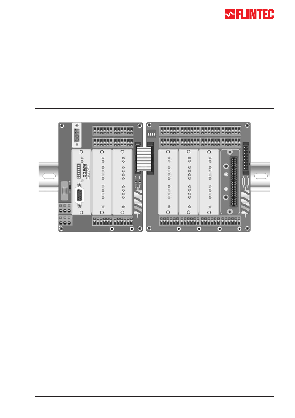
Example of MCS-64 with 5 channels and Profibus-Gateway
Page 2 Manual MCS-64
LDM 88.1
#1
Load Cell
#1
LDM 88.1
#2
Load Cell
#2
Gateway
Fieldbus
- Profibus (PGM 68.1)
- CANopen (CGM 85.1)
- Ethernet (EGM 87.1)
RS 232
Service-Port
RS485 - Bus
LDM 88.1
#64
Load Cell
#64
Base Board
MB 89.1
Extension Boards
MB 89.2
MB 89.3
MB 89.4
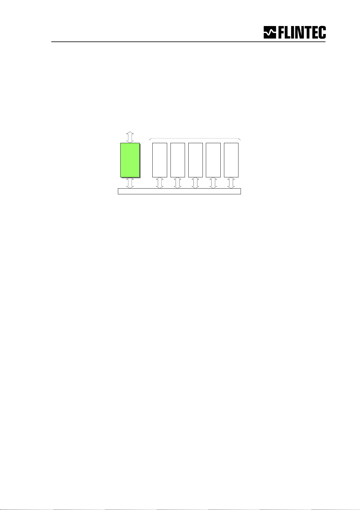
Components of MCS-64 in overview
Components of MCS-64
All boards have the same technical features:
•Spring clips for load cell terminals in 6-wire-technique
•4 DI’s via spring clip terminal blocks
•4 DO’s via spring clip terminal blocks
•Header for ribbon cable to extension board
PWR
Com
In 0
Out 0
Err
In 1
Out 1
In 2
Out 2
In 3
Out 3
LDM 88.1
LDM 88.1
PWR
Com
6
5
4
3
2
1
0
PB Adresse
Profibus Connector
Act
PGM 86.1
PGM 86.1
PWR
Com
6
5
4
3
2
1
0
Bus Adresse
CANopen Connector
Act
CANopen
CANopen
CGM 85.1
CGM 85,1
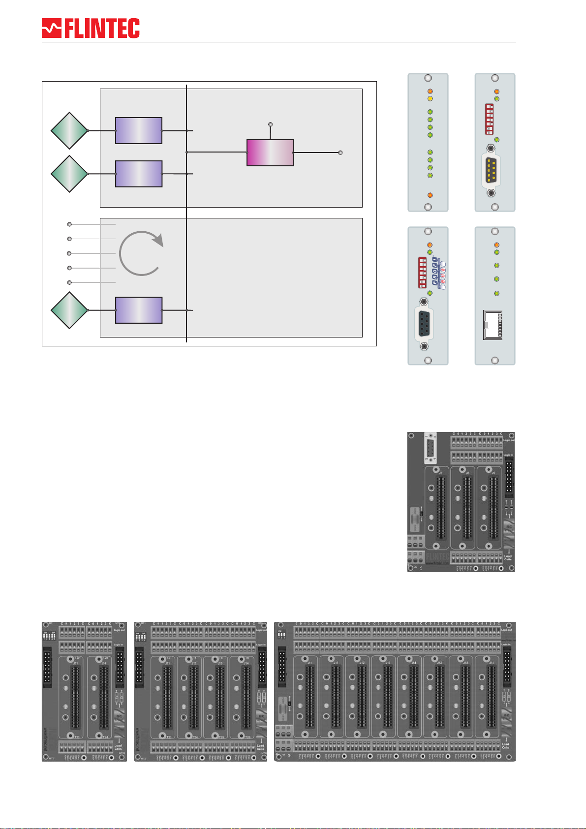
MB 89.1
Dim 104 x 135 mm
MB 89.3
Dim 129 x 135 mm
MB 89.2
Dim 79 x 135 mm
MB 89.4
Dimensions 229 x 135 mm
Base Board MB 89.1
•Slot for one Gateway CGM 85.1 / PGM 86.1 / EGM 87.1
•2 Slots for weighing processor LDM 88.1
•RS 232 Service port
PWR
Com
FD/CS
100Mbps
Link/Act
Ethernet TCP/IP
EGM 87.1
87654321
EGM 87,1
Extension Boards MB 89.2/.3/.4
•2/4/8 Slots for weighing processor LDM 88.1

Manual MCS-64 Page 3
Linearity < 0.002 % FS
Excitation 5 V DC, load cells 100-2 000 Ohm, 6 wire technique
Analogue input range ±2.2 mV/V (bipolar)
Minimum input per vsi 0.05 mV per interval non approved
Resolution ±260 000 counts , ±18-Bit-A/D convertor
Conversion rate 2400 measurements per second intern
Digital Filter FIR Filter 2.5 ... 19.7 Hz or IIR Filter 0.25 ... 18 Hz; programmable in 8 steps each
Calibration software calibration and set up
Computer interface intern RS485/RS422, full duplex, 115 200 Baud, bus capability up to 64 devices
Weighing functions zero, gross, tare, net, filter etc.
Inputs 4 opto-isolated inputs, 10 ... 30 V DC max. 3 mA
Outputs 4 OC outputs, < 35 V DC, 500 mA
Temperature effects on zero 5 ppm/°K typ.; max. < 10 ppm/°K
on span 4 ppm/°K typ.; max. < 8 ppm/°K
Temperature range –10 °C to +50 °C (operating); –30 °C to +80 °C (storage)
Enclosure Aluminium, protection IP40
Dimensions 80 x 23 x 100 mm, with two M3 fixing screws for mounting on boards MB89.1/2/3/4
Power supply 12 ... 24 V DC ±10 %, < 60 mA,(reversed voltage, burst and ESD protected)
Power consumption 1,5 W max.
EMC CE 73/23/EEC; 93/98/EEC and 89/336/EEC
Computer interface via
Service Port MB 89.1
RS232C, 115 200 Baud
Vibration withstands 1.0 G operational; 2.5 G non-operational
LDM 88.1 Specifications
Weighing Processor LDM 88.1
PWR
Com
In 0
Out 0
Err
In 1
Out 1
In 2
Out 2
In 3
Out 3
LDM 88.1
LDM 88.1
The digital weighing processor LDM 88.1 is a load cell
digitizing unit for precise measuring of loads in motion.
•± 18 bit resolution (±260 000d)
•Excitation5VDC/50mA
•2 400 Measurements/s internal,
600 Measurements/s external
•mV/V calibration
•4DI’s
•4DO’s
•RS 485 bus, 115.2 kBaud
•Digital Filter (FIR and IIR)
•for static or dynamic weighing
processes
•3 Firmware versions
Load Cell
Low-Pass
Filter
Digital Filter
IIR- / FIR
ADC
- Net
- Gros
- Average
- Dose
Digital
Output /
Setpoint
1 ... 4
Digital
Input
1 ... 4
RS 485 / 230 kBaud
binary format
LDM 88.1
Remote Control Output
Start Filling Cycle
Trigger Signal

Page Manual MSC-64
4
Contents
Part A: CANopen ............................................................................................. pages 6 - 28
Part B: Commands ..........................................................................................pages 28 - 50
Part C: Components / Technics of System MSC-64 .......................................pages 51 - 60
1Introduction...........................................................................................................6
1.1 Identification and Scope......................................................................................6
1.2 Purpose...............................................................................................................6
1.3 Acronyms and Definitions ...................................................................................6
1.3.1 Acronyms........................................................................................................6
2System Detailed Design.................................................................................7
2.1 General ...............................................................................................................7
2.2 Backplane handling.............................................................................................7
2.3 CANopen ............................................................................................................8
3CANopen profile.................................................................................................9
3.1 The PDOs ...........................................................................................................9
3.2 Communication Profile......................................................................................10
3.3 Object Directory ................................................................................................10
3.4 Quick Start Guide..............................................................................................26
3.4.1 Process data objects.....................................................................................26
3.4.2 Service data objects......................................................................................27
4COMMANDS........................................................................................................28
4.1 System diagnosis Commands – ID, IV, IS ........................................................29
4.2 Calibration Commands – CE, CM, CI, DS, DP, CZ, CG AZ, AG, ZT, FD, CS ..30
4.3 Motion detection Commands – NR, NT ............................................................34
4.4 Filter setting Commands – FM, FL, UR.............................................................35
4.5 Set Zero/Tare and Reset Zero/Tare Commands – SZ, RZ, ST, RT..................37
4.6 Output Commands – GG, GN, GT, GS.............................................................39
4.7 Setpoint Commands - Sn, Hn, An.....................................................................40
4.8 Trigger Commands – SD, MT, GA, TE, TR, TL ................................................42
4.9 Trigger Special Commands– RW, TT, TS, DT, TW, TI, HT ..............................45
4.10 Communication setup Commands – AD & BR..................................................48
4.11 Save calibration, setup and setpoint parameters Commands – CS, WP, SS...49
4.12 Filling Commands – PD1 to PD21, DI, SC, AC, GD, DT, SD............................50
4.13 Loss in Weight Commands – PL1 to PL5, LC, LI, GF, GR, GM.......................51
4.14 Speed Estimation Multi-Channel System MCS-64 ...........................................52

Manual MCS-64 Page 5
5MCS-64 Components and Configuration.................................................. 53
5.1 Base Board MB 89.1 for 1 Gateway and 2 LDM 88.x ............................................ 53
5.2 Extension Board MB 89.2 for 2 LDM 88.x.............................................................. 54
5.3 Extension Board MB 89.3 for 4 LDM 88.x.............................................................. 55
5.4 Extension Board MB 89.4 for 8 LDM 88.x.............................................................. 56
5.5 Address setup guide extension boards for 1 – 16 channels .................................. 57
5.6 Address setup guide extension boards for up to 32 channels ............................... 58
5.7 Example Check Weigher Wiring ............................................................................ 59
5.8 Example Liquid Filling Wiring................................................................................. 60
5.9 LDM 88.1 - digital Input / digital Output - .............................................................. 61
5.10 Firmware Versions ................................................................................................. 62
5.11 Appendix ................................................................................................................ 62

Page Manual MSC-64
6
1 Introduction
1.1 Identification and Scope
This document describes the system design for a CANopen Gateway (CGM85) and up to 64
Load Cell Digitizing Module (LDM88.x) using the Flintec backplane system. It describes the
functionality of the backplane, the protocol used on the backplane and the CANopen profile
used to access the LDM88 modules via the CGM85 Gateway. It specifies the protocols and
logical format of the messages between the CANopen and the local backplane system.
1.2 Purpose
The purpose of this document is to specify functionality and performance of the Gateway and
the Load Cell Digitizing Modules (LDM88) with the available firmware versions (standard
88.183, filling 88.184, loss in weight 88.185).
1.3 Acronyms and Definitions
1.3.1 Acronyms
This section includes a list of all abbreviations and acronyms used throughout the document
in alphabetical order.
CAN Controller Area Network
CANopen A higher layer protocol using the CAN.
FAT Factory Acceptance Test – the preliminary test
Function A software entity that encapsulates some computations and can be used
without worrying about its implementation
PDO Process Data Object
Process A software entity that executes a computational entity, including modules
and functions.
RPDO Receive PDO
SAT Site Acceptance Test – the final test on site.
SDO Service Data Object
TPDO Transmit PDO
Manual MCS-64 Page 7
2 System Detailed Design
2.1 General
This software connects a CANopen network to the local backplane modules. The Gateway
transports commands and responses to and from the CANbus. It scans the LDM modules for
their status and then transmits this status information continuously to the CAN controller.
CANopen
ADAPTOR
CANopen
ADAPTOR
BACKPLANE
LDM and other IO
Up to 64 modules per backplane
CAN controller
CAN BUS
Figure 1- CANopen Gateway in context
2.2 Backplane handling
The Gateway must continuously scan the backplane modules. It keeps track of which
modules are present and those that are not. The Gateway communicates with 4 levels of
priority on the backplane.
The highest priority communication is initiated on direct commands from the CAN controller
either by accessing a SDO or by using RPDO3.
The second highest priority is given to LDM modules in the final filling stage. The Gateway
reports the end of filling for each module with a TPDO2 containing the module number,
module status, and for example the dosed weight.
The third priority is the normal module scan. The Gateway continuously transmits TPDO1
with the status information for each module.
At a very low priority the Gateway looks for backplane modules that aren’t recorded as
active, in order to re-establish communication with modules that may have been restarted to
recover from failure.
The Gateway always informs the CAN controller when a module fails, or comes back online.

Page Manual MSC-64
8
2.3 CANopen
The CANopen Gateway follows the CAN2.0B recommendations. It receives both 11-bit
identifiers, and tolerates 29-bit identifiers. It only transmits 11-bit identifiers.
The Gateway is always quiet on the CANbus until the NMT Start command is received,
except for the very first ‘node guard’ message.
When started, the TPDO1 is used to send current status information. The backplane is
scanned approx. 10 times per second. This gives 64 modules X 10 = 640 status messages
per second if all 64 modules are installed. The TPDO1 holds the Gateway status, the module
number, the module status and either net or gross weight, depending on the SDO selection.
The default is the Gross value. When filling is in progress the Gateway transmits a TPDO2
every time a module changes state to ‘wait for trigger’. This TDPO2 contains the module
number, the module status and the dosed weight. In Check Weigher applications the
TPDO2 is used to send triggered measurements.
With RDPO1 frames you can send simple commands without an acknowledgement. The
functions are: select Gross or Net value in TPDO1, Set or Clear System zero, Set or Clear
Tare.
With RPDO2 frames you can send Triggers or Stop triggers. For the filling application the
trigger can be used to start the Filling Cycle. On checkweigher applications the trigger can
start measurements and a stop-trigger will stop further internal retriggers.
In case of an overrun, error or failure an EMERGENCY message is sent to the CAN
controller indicating the nature of the error or failure.
EMERGENCY messages are transmitted when the CAN controller tries to set up a module
not present, or not functioning, or when a module fails to answer the normal backplane scan
or when a module comes back on-line.
RPDO3 and RPDO4 are ignored by the Gateway.
SDOs are handled according to profile and CANopen recommendation.
The NMT protocol will use the ‘node guarding’ method (no heartbeat), but are otherwise fully
implemented
The “SDO Block Download Protocol” may be implemented later.

Manual MCS-64 Page 9
3 CANopen profile
3.1 The PDOs
The status is sent constantly to the CAN controller. The TPDO1 is sent up to 320 times per
second. This has to cover all installed modules. With a 64 LDM installation this gives 5
measurement per second per LDM, a 32 LDM installation will give 10 measurements per
second per LDM. Speed could be increased with a 16 LDM installation to 20 measurements
per second per LDM (only possible with special firmware for Gateway).
The TPDO2 is sent every time a LDM finishes a filling cycle. It has the same format and
fields as the TPDO1 except it contains the DOSED NET weight.
The format of the TPDO1 and TPDO2 is:
32 bit 16 Bit 8 bits 8 Bit
Weight Module Status Module number Gateway
State
The first field is a single precision float value containing weight information,
Gross or Net values if it is a TDPO1, and the Dosed NET weight if it is a TPDO2.
The next 16 bit field contains the module status as described below:
$0001 - Under range,
$0002 - Over range,
$0004 - Not within Zero range (not yet implemented, zero),
$0008 - Exactly zero,
$0010 - No motion, still stand, steady state,
$0020 - Tare set,
$0040 - Preset tare (0=tare is measured, 1=tare is set by user),
$0080 - Invalid weighing (wire-break, A/D ref. out of range),
$0100 - Set-point 0 (source>limit),
$0200 - Set-point 1,
$0400 - Set-point 2,
$0800 - Set-point 3,
$1000 - Filling in progress,
$2000 - Filling has completed.
$4000 - Average ready,
$8000 - Cold start.
Module number is the module (LDM) from which the data originates (0..63).
Gateway state is the state of the CANopen Gateway itself. This field is formatted as
follows:
2 bit 2 Bit 4 Bit
cmd resp reserved
“cmd” is a modulo-4 counter that increments every time a command is received i.e.
every time a SDO is received by the Gateway. If the completion of the SDO setting
requires communication with a LDM on the backplane the user can monitor the “resp”
field to determine when the LDM has acknowledged the command.
“resp” is a modulo-4 counter that increments when a command has been processed
(and a result can be fetched). If a SDO has been received, it indicates when the
Gateway has finished processing the SDO.

Page Manual MSC-64
10
The CANopen SDOs is a confirmed service, and overrun does not occur if the CAN controller
only communicates with the Gateway in the PRE-OPERATIONAL state. When a SDO has
been received by the controller no further communication takes place until the service has
been acknowledged (or a timeout occurs). However, other types of communication may fill
the Gateways internal buffer storage. In this event, the Gateway will issue an Overrun
Emergency message.
3.2 Communication Profile
The parameters which are critical for communication are determined in the communication
profile.
This includes the data for manufacturer's product nomenclature, for identification, or the
parameters for object mapping.
Abbreviations used in Tables:
ro read only
rw read / write
wo write only
(read will not be regarded as an error, but returns undefined results)
UI8 Unsigned8
UI16 Unsigned16
UI32 Unsigned32
I32 Signed32
REAL32 32 bit IEEE754 floating point
VS Visible String
3.3 Object Directory
The object directory of the CAN communication module is described below:
Please look the following pages.

Manual MCS-64 Page 11
Communication Profile (Tables)
Index Sub-
index
Name Type Attri-
bute
Default-value Meaning
1000 0 Device Type UI32 ro 00030191H Device Type
<TBD>
1001 0 Error Register UI8 ro 0 0: No error
Bit 0: General error in Gateway Module
Bit 4: Error in CAN communication module
Bit 7: Manufacturer-specific error
1005 0 COB-ID Sync messg. UI32 rw 80H COB-ID of the SYNC object
1006 0 Communication cycle
Period
UI32 ro 3125 320 Hz TDPO1 rate (3125 uS)
100C 0 Guard Time UI16 rw 320 Cycle time in ms, set by the NMT Master or the configuration tool.
Index 100Ch and 100Dh are used if index 1017h is ero.
100D 0 Life Time Factor UI8 rw 3 Wait time is set by the NMT Master or the configuration tool.
100E 0 Node guarding identifier UI32 ro 0x700 +
NodeID
Node guarding identifier
1010 0
1
2
Number of elements
Save all
Save communication
UI8
UI32
UI32
ro
rw
rw
2
0
0
Number of Store parameters entries
Save everything that can be saved
Same as sub 01 but only CAN com. parameters are saved
1014 0 COB-ID Emergency
Message
UI32 ro 80H + NodeID
COB-ID of the Emergency Object
1017
0 Heartbeat Time UI16 rw 0 Producer Heartbeat time in ms. If index 1017h is non-zero the Heartbeat
protocol is used, otherwise the Node-guard protocol is used.
1018 0
1
2
3
4
Identity Object
Vendor ID
Product Code
Revision Number
Serial Number
UI8
UI32
UI32
UI32
UI32
ro
ro
ro
ro
ro
4 Number of entries
Vendor ID
Product Code
Revision Number
Serial Number

Manual MCS-64 Page 12
Index Sub-
index
Name Type Attri-
bute
Default-value Meaning
1400
0
1
2
Number of elements
COB-ID
Transmission type
UI8
UI32
UI8
ro
ro
ro
2
200H +
NodeID
FFH
Communication parameters of 1st Receive PDO
Determined using the CANopen minimum system ID assignment
procedure.
Asynchronous communication.
1401 0
1
2
Number of elements
COB-ID
Transmission type
UI8
UI32
UI8
ro
ro
ro
2
300H +
NodeID
FFH
Communication parameters of 2
nd
Receive PDO
Determined using the CANopen minimum system ID assignment procedure.
Asynchronous communication.
1402 0
1
2
Number of elements
COB-ID
Transmission type
UI8
UI32
UI8
ro
ro
ro
2
80000400H +
NodeID
FFH
Communication parameters of 3
rd
Receive PDO
Determined using the CANopen minimum system ID assignment procedure.
Asynchronous communication.
1403 0
1
2
Number of elements
COB-ID
Transmission type
UI8
UI32
UI8
ro
ro
ro
2
80000500H +
NodeID
FFH
Communication parameters of 4
th
Receive PDO
Determined using the CANopen minimum system ID assignment procedure.
Asynchronous communication.
1600
0
1
2
Entries in Rx PDO 1
1
st
Object: LDM #
2
nd
Object Cmd. Byte.
UI8
UI32
UI32
ro
ro
ro
2
20060108
20060308
Mapping parameters of the 1
st
Receive-PDO
Object is a bitwise command
:
Bit7 Bit6 Bit5 Bit4 Bit3 Bit2 Bit1 Bit0
Cmd: SnG SnN ST RT SZ RZ
1601
0
1
2
Entries in Rx PDO 2
1
st
Object: LDM #
2
nd
Object Cmd. Byte.
UI8
UI32
UI32
ro
ro
ro
2
20060108
20060408
Mapping parameters of the 2
nd
Receive-PDO
Object is a bitwise command
:
Bit7 Bit6 Bit5 Bit4 Bit3 Bit2 Bit1 Bit0
Cmd: TR TS
1602
0 Number of mapped
Entries in Rx PDO 3
UI8 ro 0 Mapping parameters of the 3
rd
Receive- PDO (disabled)
1603
0 Number of mapped
Entries in Rx PDO 4
UI8 ro 0 Mapping parameters of the 4
th
Receive-PDO (disabled)

Manual MCS-64 Page 13
Index Sub-
index
Name Type Attri-
bute
Default-value Meaning
1800
0
1
2
3
Number of elements
COB-ID
Transmission type
Inhibit Time
UI8
UI32
UI8
UI16
ro
rw
rw
rw
3
180H +
NodeID
FFH
10
Communication parameters of 1
st
Transmit PDO
Determined using the CANopen minimum system ID assignment procedure.
Asynchronous communication.
Transmit inhibit time of PDO in 100 µs steps. A repeated transmission of the
PDO is prevented within the defined interval of the inhibit time.
Cyclic sending of PDO value (default 640 times / sec.)
1801
0
1
2
3
Number of elements
COB-ID
Transmission type
Inhibit Time
UI8
UI32
UI8
UI16
ro
rw
rw
rw
3
280H +
NodeID
FFH
10
Communication parameters of 2
nd
Transmit PDO
Determined using the CANopen minimum system ID assignment procedure.
Asynchronous communication.
Transmit inhibit time of PDO in 100 µs steps. A repeated transmission of the
PDO is prevented within the defined interval of the inhibit time.
Event based sending of PDO value (when a dosed value is present)
1802
0
1
2
3
Number of elements
COB-ID
Transmission type
Inhibit Time
UI8
UI32
UI8
UI16
ro
rw
rw
rw
3
380H +
NodeID
FFH
10
Communication parameters of 3
rd
Transmit PDO
Determined using the CANopen minimum system ID assignment procedure.
Asynchronous communication.
Transmit inhibit time of PDO in 100 µs steps. A repeated transmission of the
PDO is prevented within the defined interval of the inhibit time.
Event based sending of PDO value (when Rx PDO 3 has been processed by
the system)
1803
0
1
2
3
Number of elements
COB-ID
Transmission type
Inhibit Time
UI8
UI32
UI8
UI16
ro
ro
ro
ro
3
80000480H +
NodeID
FFH
10
Communication parameters of 4
th
Transmit PDO
Determined using the CANopen minimum system ID assignment procedure.
Asynchronous communication.
Transmit inhibit time of PDO in 100 µs steps.
(not used, will not be transmitted)

Manual MCS-64 Page 14
Index Sub-
index
Name Type Attri-
bute
Default-value Meaning
1A00
0
1
2
3
4
Number of mapped
Entries in Tx PDO 1
1
st
Object
2
nd
Object
3
rd
Object
4
th
Object
UI8
UI32
UI32
UI32
UI32
ro
ro
ro
ro
ro
8
20000220H
20020110H
20020208H
20020308H
Mapping parameters of the 1
st
Transmit-PDO
32 bit IEEE754 floating point weight value.
Module Status
Module ID [0...63]. The current module scanned.
Gateway Status
1A01
0
1
2
3
4
Number of mapped
Entries in Tx PDO 2
1
st
Object
2
nd
Object
3
rd
Object
4
th
Object
UI8
UI32
UI32
UI32
UI32
ro
ro
ro
ro
ro
8
20010420H
20020110H
20020208H
20020308H
Mapping parameters of the 2
nd
Transmit-PDO
32 bit IEEE754 floating point, default: dosed net value.
Module Status
Module ID [0..63]. The current module scanned.
Gateway Status
1A02
0 Number of mapped
Entries in Tx PDO 3
UI8 ro 0 Mapping parameters of the 3
rd
Transmit- PDO (disabled)
1A03
0 Number of mapped
Entries in Tx PDO 4
UI8 ro 0 Mapping parameters of the 4
th
Transmit-PDO (disabled)

Manual MCS-64 Page 15
Index Sub-
index
Name Type Attri-
bute
Default-value Meaning
2000
0
1
2
3
4
5
6
Number of entries
Gross weight
Net Weight
Tare
Dosed weight
Dosed tare
Average weight
UI8
REAL32
REAL32
REAL32
REAL32
REAL32
REAL32
ro
ro
ro
ro
ro
ro
ro
6
Number of entries in command input array.
Weight values as 32 bit IEEE754 floating point.
2001
0
1
2
3
4
5
6
7
8
9
10
11
Number of entries
Gross weight
Net Weight
Tare
Dosed weight
Dosed tare
Average weight
A/D sample
H&B Device ID
H&B FW Version
Device Status
ADC Reference
UI8
I32
I32
I32
I32
I32
I32
I32
I32
I32
I32
I32
ro
ro
ro
ro
ro
ro
ro
ro
ro
ro
ro
ro
11
Number of entries in info array.
Weight and info values as 32 bit signed integer
2002
0
1
2
3
Number of entries
1
st
Object
2
nd
Object
3
rd
Object
UI8
UI16
UI8
UI8
ro
ro
ro
ro
4
Number of objects in the dosed result.
Module Status
Module ID [0...63]. The module that finished a filling cycle.
Gateway Status
2003
0
1..16
Number of entries
Hardware ID bytes
UI8
UI8
ro
ro
16
Number of bytes in hardware identification array.

Manual MCS-64 Page 16
Index Sub-
index
Name Type Attri-
bute
Default-value Meaning
2004
0
1
2
3
4
5
6
Number of entries.
Save:
Analog output
Calibration
General set-up
Dosing parameters
Set-points
Loss in Weight
UI8
UI8
UI8
UI8
UI8
UI8
UI8
ro
wo
wo
wo
wo
wo
wo
5
LDM #
LDM #
LDM #
LDM #
LDM #
LDM #
Number of parameters.
Save LDM settings (Valid LDM # is [0..63].)
save analog output parameters,
save calibration settings,
save general set-up parameters,
save dosing setup parameters,
save set-point parameters.
save loss in weight parameters
2005
0
1
2
3
Number of entries
START filling process
ABORT filling process
TRIG filling cycle
UI8
UI8
UI8
UI8
ro
wo
wo
wo
3
LDM #
LDM #
LDM #
START filling process
ABORT filling process
TRIG the next filling cycle
2006
0
1
2
3
4
Number of entries
LDM select [0..63]
Factory Default
Direct command 1
Direct command 2
UI8
UI8
UI8
UI8
UI8
ro
wo
wo
wo
wo
4
LDM#
LDM#
Number of system entries.
Restores the factory defaults, if the TAC is enabled.
Direct bitwise command byte 1 to LDM
Direct bitwise command byte 2 to LDM
Commands bits are:
Bit7 Bit6 Bit5 Bit4 Bit3 Bit2 Bit1 Bit0
Byte1 SnG SnN ST RT SZ RZ
Byte2 TR TS
Sng,SnN: select Gross or Net in PDO1(tx),
ST,RT: Set/Reset Tare,
SZ,RZ: Set/Reset Zero,
TR: Software trigger.
TS: Trigger Stop; stop triggered measurement(s).
2007
0
1
2
3
Number of entries
CAN speed
CAN address
LDM Scan end
UI8
UI8
UI8
UI8
ro
rw
ro
rw
1
2
DIP-SW
15
CAN parameters (changes take effect after restart)
1=1Mbit; 2=500Kbit; 3=250Kbit; 4=125Kbit; 5=50Kbit.
The CANopen address. (DIP-SW on MCS-64)
Last LDM module to include in the scan (default: 16 LDM modules).

Manual MCS-64 Page 17
Index Sub-
index
Name Type Attri-
bute
Default-value Meaning
2100 -
213F
for
LDM
0..63
0
1
2
3
4
5
6
7
8
9
10
11
12
13
14
15
16
17
18
19
Number of entries.
1
st
Parameter
2
nd
Parameter
3
rd
Parameter
4
th
Parameter
5
th
Parameter
6
th
Parameter
7
th
Parameter
8
th
Parameter
9
th
Parameter
10
th
Parameter
11
th
Parameter
12
th
Parameter
13
th
Parameter
14
th
Parameter
15
th
Parameter
16
th
Parameter
17
th
Parameter
18
th
Parameter
19
th
Parameter
UI8
I32
I32
I32
I32
I32
I32
I32
I32
I32
I32
I32
I32
I32
I32
I32
I32
I32
I32
I32
ro
rw
rw
rw
rw
rw
rw
rw
rw
rw
rw
rw
rw
rw
rw
rw
rw
rw
rw
rw
19 Number of parameters.
Analog source
Analog high
Analog low
Filter setting
Filter Factor
Digital Outputs
Digital Inputs
Measuring Time
Filter mode
No-motion range
No-motion time
Digital outputs mask
Tare
Start Delay
Trigger Edge
Trigger Level
Update rate
Zero track (TAC protected)
∆Time
21FF
0
Number of entries.
As for 2100-2163
UI8 wo
Number of general parameters.
As for 2100 – 213F, except this is WRITE ONLY and the settings are
broadcasted to all LDMs.

Manual MCS-64 Page 18
Index Sub-
index
Name Type Attri-
bute
Default-value Meaning
2200 -
223F
for
LDM
0..63
0
1
2
3
4
5
6
7
8
9
10
11
12
13
14
15
16
17
18
19
20
21
Number of entries.
1
st
Parameter
2
nd
Parameter
3
rd
Parameter
4
th
Parameter
5
th
Parameter
6
th
Parameter
7
th
Parameter
8
th
Parameter
9
th
Parameter
10
th
Parameter
11
th
Parameter
12
th
Parameter
13
th
Parameter
14
th
Parameter
15
th
Parameter
16
th
Parameter
17
th
Parameter
18
th
Parameter
19
th
Parameter
20
th
Parameter
21
st
Parameter
UI8
I32
I32
I32
I32
I32
I32
I32
I32
I32
I32
I32
I32
I32
I32
I32
I32
I32
I32
I32
I32
I32
ro
rw
rw
rw
rw
rw
rw
rw
rw
rw
rw
rw
rw
rw
rw
rw
rw
rw
rw
rw
rw
rw
19 Number of filling parameters.
Pre-fill mode
Correction factor for in-flight value in percent. Range: 0..50.
Zero check average time (in milliseconds)
Tare delay (in milliseconds)
Tare average time (in milliseconds) 0= Tare off
Delay after pre-fill (in milliseconds).
Blanking time (in milliseconds) after coarse valve shuts OFF
In-flight delay time (in milliseconds)
Dosed weight average Time (in milliseconds)
Zero tolerance (in increments).
Tare reference (in increments).
Tare tolerance (in increments).
Pre-fill level (in increments). Set-point for 1
st
pre-filling.
Fine-fill weight (in increments)
Filling weight (in increments).
In-flight value (in increments).
Pre-fill level (in increments). Set-point for 2
nd
pre-filling.
Fill timeout value (in milliseconds)
Underweight post fill time
Tare interval – the number of fillings per tare measurements
Bad rupture blanking
22FF
0
Number of entries.
As for 2200-2263
UI8
Ro
wo
17 Number of filling parameters.
As for 2200 – 223F, except this is WRITE ONLY and the settings are
broadcasted to all LDMs.

Manual MCS-64 Page 19
Index Sub-
index
Name Type Attri-
bute
Default-value Meaning
2300 -
233F
for
LDM
0..63
0
1
2
3
4
5
6
7
8
9
10
11
12
Number of entries.
Absolute gain
Absolute zero
Calibrate enable
Calibrate gain
Set calibration point B
Set calibration point A
Calibrate max
Calibrate min
Calibrate save
Calibrate zero
Decimal point
Display step size
UI8
I32
I32
I32
I32
I32
I32
I32
I32
I32
I32
I32
I32
ro
rw
rw
rw
rw
rw
rw
rw
rw
rw
rw
rw
rw
12 Number of calibration parameters.
Absolute gain calibrate (TAC protected)
Absolute zero calibrate (TAC protected)
Calibrate enable (enables TAC when the TAC is written)
Calibrate gain (TAC protected)
Set calibration point B
Set calibration point A
Calibrate max (TAC protected)
Calibrate min (TAC protected)
Calibrate save (TAC protected)
Calibrate zero (TAC protected)
Decimal point (TAC protected)
Display step size (TAC protect)
23FF
0
Number of entries.
As for 2300-233F
UI8
ro
wo
12 Number of calibration parameters.
As for 2300 – 233F, except this is WRITE ONLY and the settings are
broadcasted to all LDMs.

Manual MCS-64 Page 20
Index Sub-
index
Name Type Attri-
bute
Default-value Meaning
2400 -
243F
for
LDM
0..63
0
1
Number of entries
Dose Info
UI8
UI16
ro
ro
1
Read the dose info:
Bit value Meaning
$0001 Coarse valve open
$0002 Fine valve open
$0004 Dose program running
$0008 Not used
$0010 Not used
$0020 Not used
$0040 Tare out of range – no filling in this cycle
$0080 Zero out of range
$FF00 The High byte has the following interpretation:
- 00= Idle
- 01= Waiting for trigger(2
nd
trigger)
- 02= Bottle on, calculating tare
- 03= Pre-fill
- 04= Main Filling
- 05= Fine Filling
- 06= In-flight delay
- 07= Post fill calculations
- 08= Post Filling
Table of contents
Other Flintec Media Converter manuals


Popular Media Converter manuals by other brands


H&B
H&B TX-100 Installation and instruction manual

Bolin Technology
Bolin Technology D Series user manual

IFM Electronic
IFM Electronic Efector 400 RN30 Series Device manual

GRASS VALLEY
GRASS VALLEY KUDOSPRO ULC2000 user manual

Linear Technology
Linear Technology DC1523A Demo Manual

Lika
Lika ROTAPULS I28 Series quick start guide

Weidmuller
Weidmuller IE-MC-VL Series Hardware installation guide

Optical Systems Design
Optical Systems Design OSD2139 Series Operator's manual

Tema Telecomunicazioni
Tema Telecomunicazioni AD615/S product manual

KTI Networks
KTI Networks KGC-352 Series installation guide

Gira
Gira 0588 Series operating instructions

Lika
Lika SFA-5000-FD user guide